1
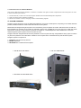
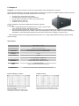
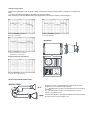
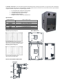
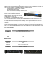
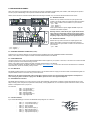
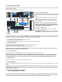
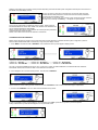
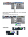
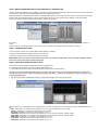
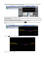
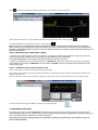
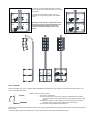
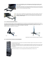
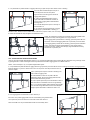
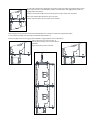
2013
USER´S MANUAL
DOUGLAS-8000
COMPACT SYSTEM DSP CONTROLLED
REMOTE MONITORING AND CONTROL
INDICE
1.- Safety Instructions .................................................................................................. Page 5
2.- Declaraction on Conformity ................................................................................... Page 7
3.- Introduction to Owner´s Manual ............................................................................ Page 8
4.- System Overview .................................................................................................... Page 8
5.- DOUGLAS-8 Line-array.......................................................................................... Page 9
6.- BP-212 Subwoofer ................................................................................................. Page 11
7.- MX-8000D Amplifier ............................................................................................... Page 12
8.- MX-8000D Rear Panel33333333333333333..33333..333 Page 13
9.- MX-8000D Front Panel 333333333333333333333.33.3... Page 14
10.- Front Panel Display Control
Factory Presets Selection 3333333333333333333.3..33... Page 14
11.- Musicson Dsp Control Software 33333333333333.................33 Page 16
11.1.- Introductionn. Star Network Tipology 3333333........................... Page 16
11.2.- Musicson DSP Control Software Installation33333.333...33.. Page 16
12.- Musicson Dsp Control Software Management .................................................... Page 17
12.1.- Introduction ............................................................................................... Page 17
12.2.- MDCS Quick Start. Connecting one MX-8000D channel 3.3333..3 Page 17
13.- Gouping Functions................................................................................................... Page 23
14.- Factory Presets Selection
Depending on Douglas-8000 Configuration 33333333333333.33 Page 25
15.- Douglas-8000 Rigging System ............................................................................... Page 27
15.1.-Rigging System Overview ............................................................................ Page 27
15.2.-Optional Accessories ................................................................................... Page 28
15.2.1.- Elevation Frame 333333333333333.3333.33. Page 28
15.2.2.- Elevation Stand 33......................................................................... Page 28
15.2.3.- Douglas-8000 Tower 33333333333333333333 Page 29
15.2.4.- Grazier 3333333333333333333333333.... Page 32
15.2.5.- Base with Wheels for Tower 333333333333333..3 Page 33
15.3.- Douglas-8000 Stacked System Assembly 3333333333333... Page 33
15.4.- Douglas-8000 Elevation System 333333333333333333. Page 34
15.5.- Douglas-8000 Fligh-Case 333333333333333333333.. Page 36
16.- Douglas-8000 Connections 33333333..33333333333333..3 Page 36
17.- Douglas-8000 System Configuration examples 333333333333333 Page 38
18.- Limted Warraty............................................................................................................ Page 39
DOUGLAS-8000
COMPACT LINE-ARRAY SYSTEM
1.- Safety instructions for admittance in the product's User's Manual
• Read the information for use (user manual).
• Please keep the user manual in a safe place during the lifetime of the product. The user manual
forms an integral part of the product. Reselling of the product is only possible if the user manual is
available. Any changes made to the product have to be documented in writing and passed on to
the buyer in the event of resale.
• Heed all warnings.
• Follow all instructions.
• Do not use this product near water (for example, in damp rooms or near a swimming pool).
• Clean only with dry cloth.
• Do not cover the heat sink. Install in accordance with the user manual.
• Do not install near any heat sources such as radiators, heat registers, stoves, or other apparatus
that produce heat.
• Protect the power cord from being walked on, pinched or damaged in any other way. Pay
particular attention to plugs and the point where they exit from the Amplifier Unit.
• The product may only be used in accordance with the information provided in the user manual.
Before and during the usage of the amplifier please ensure that all recommendations, especially
the safety recommendations in the user manual, are adhered to. The Amplifier Unit is designed for
the amplification of pulsed audio signals and the Amplifier Unit should only be connected to
speakers with an average impedance that is not lower than the impedances specified in the User's
Manual.
• Do not place the product on an unstable cart, stand, tripod, bracket, or table. The device may fall,
causing serious injury, and serious damage to the device itself.
• The Amplifier Unit can only be disconnected from the power supply by removing the plug, which
must be freely accessible at all times. Unplug this Amplifier Unit during lightning storms or when
unused for long periods of time.
• Refer all servicing to qualified service personnel.
Damages that require service
Unplug the Amplifier Unit from the mains supply and refer to your dealer/distributor or other authorised
repair workshop. Servicing is required when
1. The power-supply cord or plug has been damaged,
2. Liquid has been spilled or objects have fallen into the amplifier,
3. The amplifier has been exposed to rain or moisture,
4. The amplifier has been dropped or suffered damage in any other way,
5. The amplifier exhibits a distinct change from its normal function or performance.
Servicing
Do not attempt to service this product yourself. As opening or removing covers may expose you to
dangerous voltage or other hazards, the amplifier may only be opened by qualified personnel. Please refer
to your dealer/distributor.
Servicing and Replacement Parts
All service and repair work must be carried out by an authorised dealer/distributor. When replacement
parts are required, please ensure that the dealer/distributor only uses replacement parts specified by the
manufacturer. The use of unauthorised replacement parts may result in injury and/or damage through fire or electric shock or other electricityrelated hazards.
Safety Check
Upon completion of any service or repairs to this product, ask the dealer/distributor to perform safety
checks to determine that the amplifier is in proper operating condition.
Read the information for use
When shipping the product, always use the original shipping carton and packing materials. For maximum
protection, repack the unit as it was originally packed at the factory.
Environments
Use this product only in E1, E2, E3 or E4 environments according to EN55103-2
“Electromagnetic compatibility – Product family standard for audio, video and audio-visual and
entertainment lighting control apparatus for professional use – Part 2: Immunity”
Ventilation and heat sink
The heat sink is provided to ensure reliable operation of the Amplifier Unit and to protect it from
overheating. The heat sink must not be blocked or covered. This product should not be installed unless
proper ventilation is provided or manufacturer’s instructions have been adhered to.
Water And Moisture
Do not use this product near water (for example, in damp rooms or near a swimming pool).
Cleaning
Unplug the Amplifier Unit from the wall outlet before cleaning. Do not use liquid or aerosol cleaners.
Power-cord Protection
Power supply cords should be routed so that they are not likely to be walked on or pinched by items
placed upon them or against them, paying particular attention to cords and plugs, and the point where
they exit from the Amplifier Unit.
Lightning
For added protection of the product during lightning storms, or when it is left unattended and unused for
long periods of time, unplug it from the wall outlet. This will prevent damage to the product due to
lightning and power-line surges. Disconnection from the mains power supply can only be achieved by
removing the plug from the mains socket and by external disconnection of all poles from the mains.
Interference of external objects and/or liquids with the appliance
Never push objects of any kind into this product through openings as they may touch dangerous voltage
points or short out parts that could result in a fire or electric shock. Never spill liquid of any kind on the
amplifier.
Accessories
Do not place this product on an unstable cart, stand, tripod, bracket, or table. The product may fall,
causing serious injury, and serious damage to the product. Any mounting of the product should follow the manufacturers instructions, and
should use a mounting accessory recommended by the manufacturer.
Connecting
When you connect the Amplifier Unit to other equipment, turn off the power and unplug all of the
equipment from the supply source. Failure to do so may cause an electric shock and serious personal
injury. Read the user's manual of the other equipment carefully and follow the instructions when making
the connections.
Sound Volume
Reduce the volume to minimum before you turn on the amplifier to prevent sudden high levels of noise
which may cause hearing or speaker damage.
SPEAKON connectors
WARNING: SPEAKON connectors marked with the lightning flashes indicate high voltages that are
potentially life threatening.
Wiring to these terminals requires installation by an instructed person and the use of ready-made leads or cords.
Custom wiring should only be carried out by qualified personnel.
To prevent electric shock, do not operate the product with any of the conductor portion of the speaker
wire exposed.
NOTE: For reasons of safety and performance, use only high-quality fully insulated speaker cables of
stranded copper wire. Use the largest wire size that is economically and physically practical, and make
sure the cables are no longer than necessary.
Precautions when connecting to MAINS IN and MAINS LINK
When mounting or connecting the product always disconnect it from mains. Only connect the product to
an appropriate AC circuit and outlet, according to the requirements indicated on the rating plate.
If a power cut occurs while the amplifier is switched on, it will restart automatically once the power supply
has been restored. All settings prior to the loss of power will be maintained.
IMPORTANT: Always connect the Product to mains through the MAINS IN connector on the Amplifier Unit.
IMPORTANT: Always use ready-made mains cables with original POWERCON connectors when connecting the product to mains.
IMPORTANT: When disconnecting the Product from the mains, always disconnect at the mains end first,
before disconnecting the PowerCon connector at the Product end.
IMPORTANT: Only connect additional Products to the MAINS LINK connector keeping within the specified power rating. Always use
ready-made mains link cables with original POWERCON connectors.
DO NOT REMOVE MAINS CONNECTOR GROUND, IT IS ILLEGAL AND DANGEROUS.
2.- Declaration on conformity - international EMC directives
For admittance in the product's User's Manual
The purpose of this section is to state the important declarations on conformity in accordance with
international EMC and EMI directives, which must be entered into the User's Manual for the final selfpowered loudspeaker.
EC Declaration of Conformity in accordance to EC Directives
electro-magnetic compatibility (Council Directive 89/336/EEC,
as amended by Directives 92/31/EEC and 93/68/EEC);
low-voltage electrical equipment (Council Directive 73/23/EEC )
This product conforms to the following standards:
EN55103-1 Emission
EN55103-2 Immunity
The operating conditions and application environments presupposed in the information for use (user
manual) are to be kept accordingly.
3.- INTRODUCTION TO OWNERS MANUAL
This Owner´s Manual has been divided in 3 Sections to facilitate user right an easier comprehension about his product in order
to obtain maximum performance:
1.- Product Manual; in which user can find all points related with final assembled product Operation.
2.- DSP Command Centre Software Installation
3.- Ethernet connection: Control, Grouping and On-Line Monitoring Signals
4.- SYSTEM OVERVIEW
Douglas 8 system represents one of the latest MUSICSON line array system developments, responding to the market demands:
powerful, reliable, flexible and small format reinforcement sound systems.
MUSICSON has designed Douglas 8 system to be used either by rental companies for small to mid-sized venues as well as in
fixed installation for musicians or Dj´s looking for extremely compact size, portability and very easy set up. Its crystal clear audio
performance, extremely constant frequency response over distance, controlled dispersion and incredible SPL to size ratio
makes Douglas 8 system a perfect choice to any kind of event.
Douglas 8 has been designed with all necessary hardware to ensure a quick and easy configurable line array system to achieve
any kind of requirements: from stand-alone cabinets to more complex flown or stacked line array and subwoofer system.
Douglas 8 system is composed of:
1.- Douglas 8 compact line array element.
2.- BP-212 Subwoofer
3.- MX-8000D DSP Controlled Power Amplifier.
1.- DOUGLAS-8 LINE ARRAY
3.- MX-8000D SYSTEM AMPLIFIER
2.- BP-212 SUBWOOFER
5.- Douglas 8
Douglas-8 is an extremely compact 8” two way line-array element with an amazing SPL to size ratio.
MUSICSON has developed a new slightly curved high way acoustic lens to provide a controlled and phase-coherent wave-front
with an extreme mid and high frequencies definition and sonic accuracy.
•
•
•
•
•
Powerful 2 way compact line-array system
New MUSICSON neodymium magnet transducers
Precise vertical coverage control due to new acoustical lens
Exceptional SPL to size ratio
Versatile, easy to fly and carry.
Douglas-8 features a new premium MUSICSON neodymium high SPL
transducers:
1. One 8” lightweight speaker assembled with a 2” ( 52mm ) long excursion
voice coil with a powerful 4” Neodymium magnet.
2. One High frequency Transducer. Consist on a powerful 1.75” polymer diaphragm to increase very high frequency
response with less distortion than metallic ones but increasing lifespan due to higher resistance to mechanical fatigue.
Assembled in a new MUSICSON proprietary wooden made acoustic lens for a slightly curved wave-front.
New DOUGLAS-8 features an integrated flying hardware with 0º to 14º splay angle adjustment allowing a precise vertical
system coverage.
Specifications
Frequency Response
76Hz – 19.5KHz ( ± 3 dB )
70Hz – 20KHz ( - 10 dB )
Horizontal coverage
90 deg. Up to 16 KHz (-6 dB);
110 deg. Up to 16 KHz (-10 dB)
Individual : 15º ( -10dB / 16KHz )
System: Number of boxes and splay angles dependant
LF: 1 x 8”: 2” ( 52mm ) Voice Coil. 4” Nedymium magnet
HF: 1 x 1.75”. Compression driver. Polymer diaphragm. 3.5” Nedymium magnet
Vertical Coverage
Components
Impedance
Dimensions
LF: 16Ω
HF: 16Ω
1700 Hz
LF: 1 x 200W RMS / 1 x 800W Peak
HF: 1 x 80W RMS / 1 x 320W Peak
LF: 96dB ( 1W/1m ) / 126dB ( Peak )
HF: 107dB ( 1W/1m ) / 132dB ( Peak )
( Height x Width x Depth ) : 238 x 480 x 315 mm
Weight
Cabinet
Finish
Grllle
Rigging System
Cabinet angles
11.5Kg
12mm Marine Plywood
Black Bi-Component Poly-Impact® Polyurea based
1mm perforated Steel. Black Epoxy painted
Inside box integrated flying hardware
From 0º to 14º. From 0º to 6º in 1º steps and from 6º to 14º in 2º steps
X-Over Frequency
Power Handling
Sensitivity
Frequency Response ( 1W/1m )
Impedance Curves
Figure shows Douglas-8 Frequency Response
In anechoic conditions.
Mic. placed at 1m distance from cabinet on axis
An MLS signal was used with 4V output amplitude
Figure shows both Low and High Impedance ways.
Measurements made with 4V constant output voltage
Vertical Coverage Curves
Figures show 4 Douglas-8 units in typical J-Shape configuration. Microphone was placed in a distance of 4 meters from
array.
A ½ octave smoothing filter applied. All graphs from 200Hz to 20KHz
Each Frequency curve was obtained along array length each 5cm from top to bottom 4 units Douglas-8.
1.- Shows 4 units placing microphone
from top to 1/3 array length.
2.-Shows 4 units placing microphone
in array main lobe region.
MEASURES
D
D
O
O
U
U
G
G
L
L
A
A
S
S
3.- Shows 4 units placing microphone
from bottom to 1/3 array length.
Frequency Response over Distance
DOUGLAS-8
Shows 4 units placing microphone
At 2m, 4m, 8m and 16m from array.
BACK PLATE DIAGRAM CONNECTIONS
Douglas-8 Line-array is a Bi-Amplified system. Both signals should be
connected to 4 pin in NL4MP back plate Speakon.
+1 y -1 NL4MP Speakon should be connected directly to 8” Low Frequency
Transducer.
+2 y -2 NL4MP Speakon should be connected directly to 1.75” High
Frequency Compression Driver.
Second NL4MP Speakon in back plate is paralleled connected and should
be used to connect a second Douglas-8 unit.
6.- BP-212: Subwoofer is a 6º order Double Band-Pass designed Subwoofer containing two powerful 12” long excursion drivers. Band-Pass
design deliver higher SPL levels in a narrow bandwidth, minimizing speaker maximum excursion. BP-212 can either be used as ground stacked
or flyable subwoofer equipped with an integrated rigging hardware.
•
•
•
•
•
6º order Band-pass subwoofer system design
Two powerful long excursion 12” drivers
3” double-sided voice coil technology
Integrated rigging hardware
Designed for use in arrays with DOUGLAS-8.
Specifications
Frequency Response
Components
Power Handling
Sensitivity
Impedance
Dimensions
Weight
Cabinet
Finish
Grille
39.5Hz – 120Hz ( - 3 dB)
35.5Hz – 130Hz ( - 6 dB)
LF: 2 x 12” cone treatment . 3” ( 77mm ) Double-sided voice coil
2 x 500W RMS / 2 x 2000W Peak
101dB ( 1W/1m ) / 138dB (Peak)
8Ω
( Height x Width x Depth ) : 885 x 485 x 670 mm
48.5Kg
18 y 15mm Marine Plywood
Poly-impact®. Black Bi-component Polyurea based
1.5mm perturated Steel. Black Epoxy painted
BP-212 Frequency Response
BP-212 Measures
Figure shows BP-212DA Frequency Response
Mic. Placed at 1m in anechoic conditions with a 2.82V
Filters and correction applied in MX-8000D Amplifier
BP-212 Impedance Response
BP-212
BP-212
Figure shows BP-212 Impedance curve
With a constant 2,82V output voltage
BACK PLATE DIAGRAM CONNECTIONS
7.- MX-8000D is a dual channel 12000 W Peak 3rd Generation Power Modules featuring 2 powerful 96KHz, 64 processing bits
DSP Input modules with all necessary configuration adjustments and functions to power a complete DOUGLAS 8 system: from
a basic stand-alone Douglas 8 to a complete BP-212 Subwoofer and Douglas 8 line array.
•
•
•
•
•
Total Output Power: 2 x 2400W + 2 x 800W + 2 x 800W
Dual 96KHz, 64 bits DSP Input boards
Remote Control and Monitoring capabilities: Software available
Dual Universal Switch Mode Power Supply
Total weight: 14.2Kg
Input DSP modules have analogue Input/Link XLRs
connector as well as Remote Control and Monitoring
capabilities through Ethernet interface connectors in a Star
Network configuration. Digital AES/EBU input signals are
available under specific customer order.
MX-8000D features a 2 front panel displays, blue characters,
with a precise information about Factory presets and system parameters adjustments, together with an encoder to control
system presets and 5 led´s with each channel Input signal level information.
MX-8000D include a dual Universal Switch Mode Power Supply with automatic mains voltage selection from 85V to 265V
delivering consistent power worldwide, fully self-protected and capable to power up to 2 units of BP-212 Subwoofer and 5 units
line array DOUGLAS-8 each channel. MX-8000D DSPs include also all necessary Presets for any possible DOUGLAS 8 system
configuration.
User is allowed via Musicson Platform Control and Monitoring Software, select most convenient Factory Preset to optimize
Douglas 8 system performance depending on number of BP-212 and Douglas 8 line array cabinets used in any kind of event.
There are up to 10 Equalization filters ( Bell, Notch, Low-pass, High-pass, Band-Pass, Low-Shelf, High-Shelf ) as well as Input
Gain, Delay and Limiter per channel user definable.
Power Modules Specifications
Amplification
Output Voltages
S/N Ratio
2x4000W Continuous ( 2x2400W+2x800W+2x800W)
2x6000W Peak Clase D 3a Generación
LF: 160Vp / MF: 80Vp / HF: 80Vp loaded
Better than 120dB (A-weighted, 20Hz–20KHz, 8Ω loaded )
THD+N
<0.05% ( 20Hz-20KHz, 8Ω loaded, 3 dB below rated power )
Frequency Response
20Hz-20KHz ±0.15dB ( 8Ω loaded, 1dB below rated power)
Damping Factor
>1000 ( 8Ω loaded, 1KHz )
Protection circuits
Operation Voltage
Measures
Weight
Input Limiter, Short circuits, DC of outputs, Under & over voltage, Temperature,
Universal , Automatic Selection : 85 – 268VAC 50/60Hz
( Height x Width x Depth ) 88 x 483.5 x 555mm
14.2Kg
DSPs Specifications
DSP Processing
Latency
Signal Connectors
Nominal Input Signal
Max. Input Signal
Network connectors
96KHz, 64 bit DSP
600 µs
XLR Female / XLR Male (Link)
+6dBu
+23dBu
Etherconn RJ/45, Cat-5 y USB
Network
Remote Control
Remote Control
Parameters
Dynamic Range
10/100Mb Ethernet
Via Display y PC (User Software Included)
Input Gain, Mute, Input Delay up to 800ms (275m)
Input Limiter, Input/Outputs Signal Monitoring
120dB (Input) / 117dB (Outputs)
MX-8000D FRONT PANEL VIEW
MX-8000D REAR PANEL VIEW
8.- MX-8000D REAR PANEL.
Next, User will find a quick guide about all connectors and controls in MX-8000D amplifier back panel. Please, read carefully all this points to
ensure a proper understanding of all components related with DSP and Power modules.
Please, follow instructions and read carefully advices and warnings comments. Only one channel will be described in this section
8.1.- AUDIO IN CH1/CH2
CH-2
7
CH-1
1
3
2
4
CH-1
Neutrik XLR-3 pin female connector for Input Signal to DSP
module. Input signal module use a electronic balanced signal to
reject noises on cables. This are codes for 3 pin connector:
- pin 1 : GND
- pin 2 : Signal ( + )
- pin 3 : Signal ( - )
Under special customer request, digital AES/EBU inputs are
available in MX-8000D amplifier.
Warning!: Please, check that all your signal cables follows
right codes to avoid polarity changes. If any of this cables
change polarity in any cabinet, an important degradation in
frequency response and coverage in all system will occur.
8.2.- AUDIO OUT CH2/CH2
6
5
Neutrik XLR-3 pin male connector for Output Signal to next
Falcon-12DA cabinet. Input signal module use a electronic
balanced signal to reject noises on cables. This are codes for 3
pin connector:
- pin 1 : GND
- pin 2 : Signal ( + )
- pin 3 : Signal ( - )
8.3.- ETHERNET NETWORK CONNECTOR ( RJ45 )
RJ45 Ethercon for DSP Star Network Control and Monitoring capabilities using DSP COMMAND CENTER SOFTWARE.
Please, refer to DSP Controls Chapter and DSP Command Center Software in this Manual
8.4.- USB CONNECTOR
Use this connector only in case of new DSP Software Release Version appear for your system. In this case, a new version of Firmware for DSP
should be upload for Control and Monitoring functions.
Please, refer to DSP Controls Chapter and DSP Command Center Software in this Manual.
Any new Software Release, will appear in Musicson webpage ( www.musicson.com ) in which user will find concrete instructions to download
and Install them, as well as necessary Factory Presets.
8.5.- AC LINE INPUT
MX-8000D amplifier features a 32 Amperes Neutrik Powercon for AC Mains. Musicson supply an AC Mains cable cord assembled together 32
Amperes Neutrik Powercon Connector using a correct wire sizes.
Warning!: Do not replace supplied AC cable cord by others with less section: this will not support total amplifier consumption. In
case of using any other connector to plug unit to AC Mains, please be sure it can support 32 Amperes.
8.6.- DSP AUDIO OUT CH1/CH2
MX-8000D features a Neutrik 6-pin XLR connector to supply slave MX-8000 ( without DSPs ) amplifiers 3 Output Signals directly from Input
DSps including X-Over Frequencies, Optimization Filters, Delay, Limiting adjustments, for a cost effective system extensions. Please, consult
Musicson I+D Department for a proper use.
Pin codes are:
-
PIN 1 : Low signal ouput (+)
PIN 2 : Low signal GND
PIN 3 : Mid signal output (+)
PIN 4 : Mid signal GND
PIN 5 : High signal output (+)
PIN 6 : High signal GND
8.7.- CH1/CH2 OUTPUT
8-pin Neutrik NL8MPR type connector with MX-8000D Output Signals. Pin codes are:
-
PIN 1 (+) : Low powered Output (+)
PIN 1 (-) : Low powered Output (-)
PIN 2 (+) : Not connected
PIN 2 (-) : Not connected
PIN 3 (+) : Mid powered Output (+)
PIN 3 (-) : Mid powered Output (-)
PIN 4 (+) : High powered Output (+)
PIN 4 (-) : High powered Output (-)
9.- MX-8000D FRONT PANEL
Please, read carefully all this points to ensure a proper understanding of all components related with DSP and Power modules to optimize MX8000D features and options.
Only one channel will be described in this section
CH-1
CH-2
BP 212- D8 CH1
6 2 BP - 4 D 8 FLW 1
9.1.- INPUT SIGNAL LEVEL LEDs
BP2 12- D8 CH2
6 2 B P - 4 D 8FL W 1
MX-8000D
7
1
2
4
3
CH-2
BP212-D8 CH2
6 2B P - 4 D 8F LW1
MX-8000D
6
7
5
5 leds for Input Signal Gain Monitoring. When switch on unit, all
leds will constantly light until all initial DSPs test procedures are
finished.
3 Green leds for Input signal for -40dB, -20dB and 0dB Input
signals.
1 LIMIT Yellow led that lights when Input Limiter is acting.
1 CLIP Red led that lights when Input signal arriving to DSP
module is distorted.
Warning!: To ensure a good sound quality with very low
distortion levels and protect transducers, CLIP red led
never should be ON. User is allowed to Remote Monitoring
Input Signal Level via Musicson Software.
9.2.- “MENU” PUSHBUTTON
Pushbutton for DSP MENU Options. Please, refer to DSP
Controls Section in this Manual.
Press “MENU” pushbutton to select most convenient Factory
Preset depending on DOUGLAS-8000 system configuration.
9.3.- DISPLAY
It´s a User Interface to inform in 2 lines about “UNIT NAME” and selected FACTORY PRESET. Sirve como Interfaz de usuario para visualizar
el “Nombre de la Unidad” y el “Preset de Fábrica” seleccionado en las actuales condiciones de uso. It´s a blue color backlit screen with black
characters. User is allowed via Musicson Software to choose between 3 display configuration:
1.- ON: Default configuration. Display backlit remains always ON.
2.- OFF: Display backlit will change to OFF.
3.- DIMM: Display backlit dimmer. Will reduce intensity compared with standard ON position.
9.4.- ENCODER GAIN/EDIT
Total Encoder for EDITING and SELECTING DSP functions by pushing and rotating.
Gain adjust INPUT from -40dB ( Mute ) to +12dB.
Please, refer to DSP Controls Chapter in this Manual for further information
Warning!: Please, do not select extreme INPUT GAIN values. It will sure distort your system Sound quality. As a general rule for an
optimized Sound, please Factory Presets selected Gain.
9.5.- “EXIT” PUSHBUTTON
Pushbutton for EXIT from DSP MENU Options. Please, refer to DSP Controls Section in this Manual.
Advice: Supplied Musicson Software is a valuable tool for Monitoring and Control Signals. Musicson strongly recommend to use
Software whenever possible. You will find all necessary information and control over the system in a very easy to use and user
friendly graphical interface. Limit screen pushbuttons and controls to display UNIT NAMES and FACTORY PRESETS selected.
9.6.- ON-OFF SWICHT
Switch On and Off unit. In ON Position, switch will light in green colour.
9.7.- COOLING WINDOWS
Placed in Front and Rear panel as well as in both sides. Rear panel cooling windows let inside 4 high performance fans to intake fresh air from
outside.
Warning!: Please, keep cooling front windows and rear and sides slots without any obstacle that may inhibit air flow. In that case,
power amplifier temperature will quickly increase limiting output power for its own protection and reducing significantly DOUGLAS8000 performance and quality.
10.- FRONT PANEL DISPLAY CONTROL
FACTORY PRESETS SELECTION
MX-8000D Input DSPs can be controlled via supplied Musicson DSP Software or via front panel display controls: pushbuttons and encoder.
Front panel Display control options will be described in this section. Both “Menu” and “Exit” pushbuttons feature a double RED and GREEN
leds to check functions. There is also a total encoder ( rotate and push functions ) to select and confirm DSP parameters.
Selection and Loading most convenient Factory Presets depending on DOUGLAS-8000 system configuration basically are main functions of
MX-8000D front panel display controls.
As soon as system is switched on and during first 15 seconds, DSP and power
modules start all initial procedures to check all functions and load all parameters
corresponding to last loaded Preset.
During this time, no sound will come out from system and all Input Signal Level leds
will Light. Also, message “ Initializing3 “ will appear in system Display.
As soon as this initial check is finished and system is ready , display will show
last loaded PRESET as well as UNIT NAME. UNIT NAME is user selectable and
can be changed via Musicson SOFTWARE.
Display will show last Factory Preset selected. Also will keep all DSP parameters
configured last time system was used.
Please, refer to DSP Command Center Software in this Manual
CHANGING FACTORY PRESETS
Please, follow next steps to change to most convenient Factory Preset depending on DOUGLAS-8000 system configuration ( refere to
DOGLAS-8000 CONFIGURATION on this Manual ) using front panel display controls:
1.- Push “MENU” and rotate Encoder “GAIN/EDIT” until most desires Factory Preset appear in display screen:
-------------------------
Sequence for Number and Name Factory Presets is as follow:
PRESET Nº 1 : BP-2D8 ---------------- PRESET Nº 2: BP-2D8STC ----------- PRESET Nº 3: BO-2D8FLW1
PRESET Nº 4 : BP-2D8FLW2 ------- PRESET Nº 5: 2BP-4D8FLW1 -------- PRESET Nº 6: 2BP-4D8FLW2
The other 74 remaining PRESETS are free for user. Correct way to create new USER PRESETS is via MUSICSON DSP CONTROL
SOFTWARE. Please, refer to Musicson DSP Control Software in this Manual.
2.- Once displayed most convenient Factory Preset: Push Encoder “GAIN/EDIT” .
System will ask to confirm loading process. Rotate then Encoder GAIN/EDIT to select “Yes”; words will change to capital leters.
3.- Push Encoder GAIN/EDIT once more. DSP will load selected Factory Preset.
In case of a mistake in Factory Preset selection, user is allowed to push “EXIT” pushbutton to go back to previous sequence.
Finally, selected Factory Preset will be displayed on front panel DSP screen
11.- MUSICSON DSP CONTROL SOFTWARE
11.1.- INTRODUCTION. STAR NETWORK TIPOLOGY
MUSICSON MX Series Amplifiers offers the possibility to design a Star Network configuration via Etherconn RJ45 already supplied and
installed in Input DSP Board.
A Star Network is a local area network ( LAN ) in which all nodes ( MX Series Amplifiers ) are directly connected
via CAT5 cable to a common central Computer. With this Network topology, all MX Amplifiers will be WIRED or
WIRELESS linked to Computer by using a Hub or a Switch or a Musicson PWM-15; a 15-Port Wireless Ethernet
Switch , so it´s very easy to add or remove connected units.
In a Star Network, a cable failure will isolate ONLY the unit linked to computer with this cable. All other devices will
continue to function normally.
If any unit connected in this Network goes down, none of the other units will be affected.
All signals coming from / to any device to central computer goes directly without crossing through any other device
in the net so, communication speed is highest compared with other network topologies.
MUSICSON DSP CONTROL SOFTWARE, supplied with MX Series Amplifier, allows user both:
1.- On-Line real-time INPUT PARAMETERS CONTROL over all MX Series Amplifiers connected in the network, including FACTORY PRESETS
loading and GROUPING Functions. Please, refer to MCDS Section in this Manual.
2.- On-Line Real-Time Input/Output Signals and Limiters Monitoring over all MX Series Amplifiers connected in the network, as well as each
Output channel Impedance Load and Power modules Temperature. Please, refer to MDCS Section in this Manual.
MUSICSON DSP CONTROL SOFTWARE ( MDCS ) allows user to open as many Monitoring and Control windows as MX Series Amplifiers
Channels connected in the network. User can assign a UNIT NAME to any Amplifier in network ( It will also appear in front panel Display ) to
identify all units.
Software detects automatically all IP Addresses in the net and display all information required in opened window.
User can open or close each Amplifier Channel Control or Monitoring window as well as leave all them opened at same time.
11.2.- MUSICSON DSP CONTROL SOFTWARE INSTALLATION
MUSICSON strongly recommend to install MUSICSON DSP CONTROL SOFTWARE for all MX Amplifiers Series for Monitoring and Control
Input/Output Signals via CAT5 cable ( wired through an Ethernet Switch or wireless by using new Musicson PWM-15 module ). It´s a powerful,
friendly and easy to use system Remote Control tool including a well designed Graphical User Interface featuring also important parameters
monitoring such as both amplifiers channel Temperature and Impedance Load. Musicson DSP Con Software.
Following operating Systems are supported:
Windows XP with Service Pack 2
Windows 7
Mac OS-X 10.5.8 or higher
To install Software, please, follow this simple steps:
1.- After downloading Musicson DSP Control from Musicson website ( www.musicson.com ) open package. The installer will guide you through
installation procedures.
2.- Please, accept terms in the Licence Agreement
by clicking in right place.
Maybe, in some moments of installation procedure,
a message from windows can appear if you have a
firewall activated.
Please, go on with installation and select go on
anyway.
3.- Select the folder where you wish to have
Musicson DSP Control Software installed:
By default: Musicson\DSPControl
4.- Select NEXT and go on with installation
process.
5.- Now, installation will start.
System will need some minutes to
finish installation process.
6.- Once installation is finished, installer
will ask to install also Microsoft VisualC++
Runtime to run software correctly; please
accept installation as shown in next
figures.
9.- Finally, accept Microsoft License Terms and click on “Install”. After finishing all this steps, you will see a new icon in your Desktop to launch
Musicson DSP Control Software.
Warning!: On some Windows 7 versions, user will need to run the Software as “Administrator” to connect with hardware correctly. To
change to this mode, click with right pushbutton of your mouse and select “Properties”. Then, select “compatibility” and finally “Run
this program as Administrator”.
12.- MUSICSON DSP CONTROL SOFTWARE (MDCS) MANAGEMENT
12.1.- INTRODUCTION
MX-8000D amplifier is fully equipped from MUSICSON with Ethernet solution via RJ45 connectors in its back panel as well as DSP COMMAND
CENTER SOFTWARE for network capabilities to enable complete filters configuration, control, convenient cabinets grouping and monitoring
solutions. With its intuitive and easy-to-use graphical interface, Musicson DSP Control Software provides remote ( wired or wireless ) access to
load also FACTORY or USER PRESETS.
Each MX-8000D channel must be connected to a 100BaseT Ethernet switch using a standard CAT-5 cable. Personal Computer to run control
with Musicson Dsp Control Software must also be connected by 100BaseT connector to the switch or using a wireless access point on the same
network.
Using a wireless access point to manage Network will require additional TCP/IP protocols in user Computer as well as specific Ethernet
configurations.
12.2- MDCS: QUICK START
CONNECTING MX-8000D FOR THE FIRST TIME
Even if you have experience in handling control and monitoring software systems, it´s hardly recommended for MX-8000D users to follow this
instructions with initial test configurations starting with simplest networking. Musicson Dsp Control Software is a powerful and reliable control
and monitoring platform which can be used in any Musicson system using Input Dsp´s modules.
Note: To avoid any communication errors, please, avoid connecting the switch to any other Ethernet equipment than speaker/s and
Control Computer.
Warning!: If you are using a wireless access point with a Ethernet switch to control and monitoring your MX-8000D system, please,
NEVER use 100BaseT network connector in your Control Computer for other Network uses.
Follow next steps for a single MX-8000D unit network:
STEP 1
Connect a MX-8000D Amplifier to Control PC using a USB A-USB B ( Universal Serial Bus ) cable. First time this connection is handled, all
necessary drivers for a correct communication between Control PC and Hardware will be installed.
1.- Using a standard USB A – USB B ( Universal
Serial Bus ) cable. In this way, we will use one USB
connector of one channel in MX-8000D Back Panel
to one of USB Ports in Computer.
Please, note that DCCS will install all necessary
drivers for Computer to detect the device and will
assign automatically the most convenient COMM
Port for a successful communication.
MX-8000D
CH-2
CH-2
CH-1
CH-1
USB CONN.
Sometimes will be necessary to switch OFF your
MX-8000D amplifier for a correct drivers installation.
This process should only be handled for first
time.
BACK PANEL
USB A-USB B CABLE
CONTROL LAPTOP
2.- Using a Switch we will need to use for several MX-8000D amplifiers system.
In this case, user will connect an unmanaged
100BaseT network Switch to Ethernet connector in
MX-8000D back panel with a standard CAT-5
cable.
NETWORK
SWITCH
CH-2
CH-2
CH-1
CH-1
Connect the Computer to the Ethernet Switch with
another standard CAT-5 cable as shown in figure
From now, we will use from now this second way
as it will be the correct way to connect any MX8000D amplifier system to Control Computer; wired
or wireless.
CONTROL LAPTOP
Finally, power up your MX-8000D amplifier.
STEP 2
Launch Musicson Dsp Control Software in Windows or MAC by clicking twice in the icon. Musicson Dsp Control Software will detect
automatically, all devices connected in the network. Unit Name indicator will show a GREEN COLOUR besides detected unit if connection is
“Active”. If a YELLOW COLOUR appears in Control Center screen, please,
check all network connection, configuration and cables: there is a
communication problem and you will not be able to use Monitoring and
Control Software.
In this case, both MX-8000D channels ( CH1 and CH2 ) will be detected.
Main MENU will open Musicson CONTROL CENTER panel in upper-left
side of your Computer screen.
1.- UNIT NAME : BP212-D8 CH1/CH2. User is allowed to change UNITS NAME through Software.
2.- REFERENCE : 00:50:C2:76:AD:B3 y 00:50:C2:76:AD:B4. This is a code automatically detected. User doesn´t need to introduce
3.- ADDRESS: 192.168.2.100 y 192.168.2.101. IP Address for both MX-8000D channels automatically assigned to networked Units.
4.- GROUP: Not Grouped. Please, refer to GROUPING Units in this Manual.
5.- LAUNCH: Press with mouse over “Double Arrow” to open this unit CONTROL and MONITORING Window
STEP 3. CONTROL AND MONITORING PANELS
Click with mouse over “Double Arrow “ in Musicson CONTROL CENTER to open units CONTROL and MONITORING panel.
Then, 2 new panels will appear in your Control Computer monitor showing progress of Networked Unit PROGRESS together with UNIT CODE,
and creating CONTROL AND MONITORING panel views.
After a brief period of time, Musicson Control Center will open Monitoring panel for
selected networked unit.
As shown in picture, there is a GREEN indicator in besides “LINK”. This
mean that communication between networked unit and Control PC is
active.
NOTE: If indicator changes to RED color, means that
communication is lost. Please, check all network system
connections until GREEN color appear again.
Warning!: It is NOT ALLOWED to access to X-OVER, OUT1, OUT2,
OUT3 control panels for any changes. This panels contain all
information and adjustments for each 3 ways to optimize system
including: X-Over and optimization filters, delay, limiting and
phase.
STEP 4: MONITORIZING IN/OUT SIGNALS
User will control all INPUT, LOW , MID and HIGH OUTPUT signals by MONITORIZING this signals in opened panel.
Connect a signal source to selected Networked MX-8000D channel and play some music. Signal Levels will appear in Bar-Leds with GREEN
Lights
When Levels are High enough that Limiters start to act, YELLOW Lights will appear on Bar Leds.
If signal are so high that are distorted, RED Lights will appear on Bar Leds.
Note: Peak Signals are displayed on Bar Leds during few seconds. This will help user to fix more convenient Input Level.
Note: Please, note that IN1 and IN2 INPUTS are Linked so, in all cases, Bar leds will display same Level.
Warning!: Never let RED lights appear in any Bar Leds. This may cause important breakdowns either in speakers and power modules
STEP 5: SELECTING FACTORY PRESETS
User is allowed in any MX Series Amplifiers Dsp controlled to select most convenient Factory Preset depending on networked system
configuration via Musicson Dsp Control Software. All MX Series Amplifiers provide necessary Factory Presets to load on Dsp memory to supply
correct signal and outputs to any DSP controlled system.
In this case, MX-8000D amplifier will be supplied with Factory Presets to power next systems:
1.- FALCON-12DA passive system
2.- FALCON-212DA passive system
3.- DOUGLAS-8000 ( BP-212 and DOUGLAS-8 Line-array ) system.
User will find in this Manual all necessary references for DOUGLAS-8000 system to select most precise Factory Preset
1.- Click with left mouse button on “PRESETS UNIT” and selected unit CONTROL panel will open all stored presets
2.- Select most convenient Factory Preset depending on DOUGLAS-8000 system configuration. In this case, for a complete DOUGLAS-8000
flown system, we will have to select “2BP-4D8FLW1” Preset. This Preset will contain all necesary adjustments 2 units BP-212 y 4 flown units
DOUGLAS-8 each MX-8000D channel.
IMPORTANT!: Please; remember your MX-8000D amplifiers features 2 Input DSP modules for each CH1 and CH2 outputs. You should
select most convenient Factory Presets in BOTH CHANNELS to have same parameters.
3.- Select now with your mouse “LOAD” screen in Section “PRESETS UNIT” to load this Factory Preset in DSP memory as shown in next
figure.
A new panel will appear showing “Synchronization Progress” while software is sending all parameters to DSP memory.
NOTE: As soon as Synchronization Progress finish, selected Factory
Preset name will be displayed in both:
- MX-8000D Front panel display.
- PRESET UNIT panel in Musicson Software.
CH-1
B P2 12-D8 CH1
6 2BP-4D 8FLW 1
CH-2
B P 2 1 2 -D 8 C H 2
6 2BP-4D8FLW1
MX-8000D
CH-2
BP212-D8 CH2
6 2BP-4D8FLW1
MX-8000D
STEP 6: MONITORIZING IMPEDANCE LOADS AND MODULE TEMPERATURE.
Musicson Control DSP Software ( from now MDCS ) supplied with your MX Series Amplifiers allow also user through some complex algorithms
monitorize each output channel LOAD IMPEDANCE as well as Amplifier Temperature.
Each Power Module in MX-8000D amplifier features 4 Thermal Sensors placed in each output channel and also in Switch Mode Power Supply.
Musicson DSP Control Software ( MDCS ) will show this information at any time when “STATUS” led is GREEN. Concerning Amplifier
Temperature, Software always display most critical value ( highest Temperature )
For both Amplifier channel Temperature and Load Impedance Monitoring, please, select “Details” in “UNIT NAME” Section as shown in
picture.
Please, note that Load Impedance values can give an important information about DOUGLAS-8000 transducers conditions.
STEP 7: CHANGING INPUT GAIN
User can increase or reduce from +12dB to MUTE, INPUT GAIN by 2 methods:
- Clicking on INPUT faders and dragging upwards or downwards or
- Introducing ( writing ) directly in IN window the desired level value.
IMPORTANT!: Please, try not to use extreme Input Gain values; use 0.0dB as a standard Gain. Please, note that a ±3dB Gain change
means twice the acoustic output compared with 0.0dB.
STEP 8: USING INPUT EQUALIZATION FILTERS
As previously commented, MDCS supplied with MX Series Amplifiers allow:
1.- Input/Outputs Signals Monitoring ( refer to previous Manual Sections )
2.- Input parameters Control: X-Over and Optimization filters, Delay, Limiters and Compressors.
Although Factory Presets makes DOUGLAS-8000 system to deliver high Output Levels with a Flat Frequency Response by selecting most
convenient one, in some cases, audience area features ( buildings, trees, walls,\ ) makes some “ Equalization corrections” necessary in units
to avoid undesirable effects..
1.- Tap with mousse button over IN1 panel in MDCS. Control panel will appear in Control Computer screen:
MDCS features up to 10 Optimization filters ( including X-Over Low-Pass and High-Pass ) in each MX Series Channel. Available filters types
are:
- BELL : Selectable in any Frequency with variable Q ( 0.2 to 20 ), and Gain ( between -12 and +12dB )
- NOTCH : Selectable in any Frequency with fixed Q=10 and G=-40dB
- ALLPASS: Selectable in any Frequency with variable Q ( 1 to 25 )
- LOW-SHELF: Selectable in any Frequency with variable Q ( 3 to 25 ) and Gain ( between -12dB to +12dB )
- HIGH-SHELF: Selectable in any Frequency with variable Q ( 3 to 25 ) and Gain ( between -12dB to +12dB )
- BAND-PASS : Selectable in any Frequency with variable Q ( 0.2 to 25 )
- HIGH-PASS : Selectable in any Frequency with variable Q ( 0.5 to 2 )
- LOW-PASS : Selectable in any Frequency with variable Q ( 0.5 to 2 )
2.- User can use either Equalization panel to configure necessary EQ. filters or clicking with mouse over each point in GRAPH and dragging
with left button of mouse pressed to select Filter Frequency center and Gain.
It´s possible to use PC mouse to adjust all EQ. filter parameters.
Tap with PC mouse LEFT button over desired EQ. filter number ( square symbol ) and, while holding on, move it upwards ( increase Gain ) or
downwards ( reduce Gain ).
Tap with PC mouse RIGHT button over EQ. filter number ( square symbol ) and, while holding on, move it to the right ( increase Q with narrower
.filter bandwidth ) or left ( reduce Q with wider filter bandwidth ).
User is allowed to switch Equalization filters ON and OFF in Real-time to check sound differences in order to make filters best choice by tapping
over blue square besides EQ filter: Blue color means EQ filter ON and no color means EQ filter OFF.
Size of Graphs can be increased for a more accurate data display by selecting
levels:
1.- First size level as shown in next figure
2.- Select again
to have a full Control PC screen Graph.
Select X screen will return to standard size.
in Left Upper side on screen. There are 2 screen size
Select
to display on each EQ filter all adjusted parameters such as Frequency Center, Q and Gain.
User is allowed also to “Save” or “Print” adjustments information in a Graphical Format file ( .PNG ) by tapping
An especific bandwidth can be displayed using “Zoom” option by tapping
.
.
Warning!: Please, do not attempt to use extreme or radical EQ. filters Gain. It could deteriorate system performance and quality
Please, note that this kind of adjustments should be used only as a audience areas features corrections like trees, buildings, walls,3
Remember your MX-8000D amplifier will deliver all necessary output corrections for an optimized system performance selecting most
adequate Factory Preset.
STEP 9: USING INPUT DELAY AND SIGNAL LIMITER
1.- Input Signal can be delayed for time corrections in delay lines by entering most adequate value in “DELAY” screen in Control panel. By
default, Input signal delay is 0.00ms. Maximum Input Delay value will be 800ms that means 275 meters.
For an easier Delay adjustment, user can switch units between milliseconds, seconds, meters, feet,\
2.- Maximum Input Signal can be also Limited entering value on “LIMITER THR” screen to limit in that each 3 way máximum output power.
Limiter Release can be changed in “LIMITER REL” screen. By default, +12.00dBU.is minimum Input Signal Limiter that means each 3 way
maximum output power.
STEP 10: USING INPUT HIGH-PASS/LOW-PASS FILTER
Maybe, in some cases, could be useful to apply Input Signal X-Over filters.
Input High-Pass and Low-Pass X-Over filters ( Butterworth, Bessel and Linkwitz-Riley types) are availble to user with slopes between 6 and
24dB/Oct in Control Panel.
User can easily switch X-Over filters ON and OFF by tapping over blue square: blue color means filter ON and no color means filter OFF.
To remove X-Over filters, simply write “OFF” in Frequency X-Over filter white box.
13.-GROUPING FUNCTIONS
Working with large number of systems, GROUPING function allows user the possibility to make convenient Groups of MX Series Amplifier
Control Parameters copying from one “master” to rest of “Slave” channels same Input configuration and adjustments. This function avoid user to
enter in all individual DSP same adjustments to manually configure them.
NOTE!: Musicson Dsp Control Software allows user to select NOT TO GROUP certain parameters to have individual control even
inside a configured GROUP.
1.- Tap over “TOOLS” in Musicson Control Center panel Menu.
2.- Select “NEW GROUP” option and then write a convenient GROUP NAME. Confirm with OK.
3.- Follow this 2 simple steps to create as number of GROUPS as needed.
In this example, a GROUP will be configured with MX-8000D amplifier CH1 and CH2 called “DOUGLAS-8000”
3.1.- Select networked units to join in selected GROUP “DOUGLAS-8000” by tapping in “SETUP” window as shown in figure. A panel
“Configure Group” will be opened
Tap on “Select3” window and “Select Group Members” menu will be opened with all networked units as shown in next figure
In this case, both MX-8000D channels ( BP212-D8 CH1 and BP212-D8 CH2 ) will be selected to join in “DOUGLAS-8000” Group by tapping in
each of them in “Name” column and also in single arrow “>” to be added to Group.
Please follow this steps to add units to selected GROUP one by one. Both “Members” will automatically sent to “Group Members” screen.
Finally, tap “OK” when all Members Group have been selected. “Select Group Members” screen will close.
4.2.- Parameters that should NOT BE GROUPED
Musicson Dsp Control Software allows NOT TO GROUP parameters inside a configured GROUP to have individual members control over them.
This feature is specially important when it is necessary to control EQ. Filters, Input Delay, Input Gain, Limiting,\ or any other control
parameters individually in members inside same GROUP.
To configure “ungrouped” parameters tap “→Exceptions” window in “Configure Group” screen.
In this example, we will “ungroup” EQ. Filters PEQ in configured DOUGLAS-8000 GROUP. After “→Exceptions” is selected, user will be
requested to select exception through “Select Exceptions” Menu screen as shown in figure. Tap “All” and select which parameter would you
like to “ungroup” to have individual control. In this case EQ. Filters PEQ.
Finally Select “OK”.
Figure will show the process while MDCS is
“ungrouping” all Input PEQ filters inside DOUGLAS8000 Group.
If any other parameter should be “ungrouped”, please,
follow same steps using consecutively “All” popup
menu.
IMPORTANT!: Please, note that all adjustments
and configurations made in Input DSP´s, will remain
in memory each time MX-8000D amplifier will switch
ON again. Check before using your system, all
configuration loaded.
14.- FACTORY PRESET SELECTION
DEPENDING ON DOUGLAS-8000 SYSTEM CONFIGURATION
Both Musicson Software and front panel display controls allow user to select most convenient Factory Presets depending on DOUGLAS-8000
system configuration.
Please, follow next guide to select Factory Presets to deliver highest performance with your DOUGLAS-8000 system:
PRESET 1: STND-ALONE
Use this Factory Preset in case only Line-array elements are needed without BP-212 Subs. Please, refere to figure
in next situations:
“STAND ALONE” or Douglas-8 over stands without BP-212, “FRONT-FIELD” , or “SIDE-FIELD”
Please, be advised that Douglas-8 line-array was designed to be used with BP-212 Subs. User should be
specially careful in this situation due to Douglas-8 low frequency response limitations.
PRESET 2 : 1BP-2D8 STK1
Please, select this Factory Preset in case that DOUGLAS-8000 system is configured as shown in figure.
Factory Preset is valid for any Douglas-8 splay angles selected.
Factory Preset is also valid if 2 or 3 Douglas-8 line-array elements are used.
PRESET 3 : 1BP-2D8 STK2
Use this factory Preset in case of Douglas-8000 system with 2 or 3 line-array elements “STACKED” over 1 BP212 subwoofer system.
Factory Preset is valid for both 2 or 3 line-array elements used.
Factory Preset is also valid in cases where upper line-array should be configured for balcony in which splay
angles will be increased.
PRESET 4 : 1BP-2D8 FLW
Use this factory Preset in case of Douglas-8000 system with 2 or 3 line-array elements “FLOWN” over 1 BP-212
subwoofer system using our light-weight aluminum Douglas-8000 tower.
Factory Preset will be valid for either 2 or 3 line-array elements.
Advice: For a correct audience coverage, please select always splay angles between 0º and 3º in Douglas-8
line-array elements as shown in figure.
PRESET 5 : 2BP-4D8 STC
Use this factory Preset in case of Douglas-8000 system with line-array elements “STACKED” over 2 BP212 subwoofer system.
Factory Preset will be valid in case 3 or more ( up to a maximum of 5 ) Douglas-8 line-array stacked
elements are used.
Preset will also be valid in cases where upper line-array should be configured for balcony in which splay
angles will be increased.
PRESET 6 : 2BP-4D8 FLW1
Douglas-8000 system configuration “FLOWN1”. Using 2 BP-212 subs and, 3 up to a maximum of 5 line-array
Douglas-8 units each MX-8000D amplifier channel
For an optimized audience coverage, Musicson highly recommend a typical “J” Doulglas-8 line-array
configuration.
There are 2 possible splay angles selection for this kind of line-array configuration:
1.- 0º, 1º, 3º, 5º splay angles between Douglas-8 for Long-Throw.
2.- 0º, 2º, 4º, 8º splay angles for an improved vertical coverage.
ATENTION!: Musicson highly recommend to DOUGLAS-8000 system to use this line-array splay
angles configuration with this Factory Preset to optimize and Frequency Response and audience area
coverage.
PRESET 7 : 2BP-4D8 FLW2
Douglas-8000 system configuration “FLOWN2”. Using 2 BP-212 subs and, 3 up to a maximum of 5 line-array
Douglas-8 units each MX-8000D amplifier channel
Use this Factory Preset in case of small to very small ( up to 15 meters long ) audience áreas as well as in
cases where Douglas-8000 system should be placed over an stage or over a relatively high elevated platform.
To handle this Douglas-8000 configuration, user should select quite “closed” line-array splay angles:
1.- 0º, 4º, 8º, 12º Douglas-8 splay angles for Long-Throw.
2.- 0º, 5º, 10º, 14º Douglas-8 splay angles for improved vertical coverge.
15.- DOUGLAS-8000 RIGGING SYSTEM
Safety is the most important issue when suspending heavy-weight loads such as a Professional Sound System like DOUGLAS-8000, especially
when it´s hanging above heads of personnel; professional or not.
A deficient suspension and rigging techniques, the use of non-original DOUGLAS-8000 rigging parts, even a non appropriate equipment may
cause serious legal issues related to property damages or personal injury.
Never think all secure measures are too much: read or assist to Hoist manufacturers seminars, and consult every aspect of this business with
your Insurance Company.
Follow all rules and advices provided by your trussing system ( or any other suspension system ) manufacturer and be sure that your structure
can meet with weight requirements.
Finally, please be sure to understand and follow any Local Safety Regulations; you must strictly follow all Security Load Factors prescribed by
Authorities.
15.1.- RIGGING SYSTEM OVERVIEW
Rigging system in DOUGLAS-8000 is completely integrated in both cabinets: Douglas-8 Line-array element as well as BP-212 subwoofer.
User can configure DOUGLAS-8000 system in many ways ( Refer to Configurations in this Manual ) flying BP-212 together Douglas-8 or placing
BP-212 on the floor and flying Douglas-8 line-array elements.
To configure DOUGLAS-8000 in both ways, Musicson has developed only one Frame model in order to make easier the system flying tasks,
reducing also number of optional rigging pieces.
Douglas-8 rear rigging detail
BP-212 upper side rigging detail
BP-212 lower side rigging detail
As shown in both BP-212 subwoofer rigging plates figures, there are 4 rigging points
in cabinet upper side to fix flying Frame. There are also in lower side, 2 rigging points
market with 1 and 2 in figure for:
1.- Line-array Douglas-8 fixing point when suspending under BP-212.
2.- Second BP-212 subwoofer fixing point for suspending 2 BP-212 units.
15.2.- OPTIONAL ACCESSORIES
15.2.1.- ELEVATION FRAME
Musicson has developed only 1 Elevation Frame model to ¨fly” both BP-212 subwoofer
and Douglas-8 line-array. Frame will also be used when Douglas-8 should be “stacked”
over BP-212 Sub.
Frame is made of 60 x 10mm thickness platen steel and 3mm iron plates to ensure
necessary strength for flying a complete BP-212 and Douglas-8 elevation.
Douglas-8000 system Frame has been developed to handle up to 15 Douglas-8 Linearray elements as well as 2 BP-212 together 5 units Douglas-8.
15.2.2.- ELEVATION STAND
Specially designed to use in DOUGLAS-8000 system. It can be assembled in both upper and one lateral sides of BP-212 subwoofer, to use a
máximum of 3 line-array Douglas-8 cabinets.
Stand features 3 height points which may be secured by a supplied lock pin.
Douglas-8 will be assembled to stand through a dedicated wooden platform.
Wooden Platform
3 Position Douglas-8000 cabinet stand
Douglas-8000 assembled stand
BP-212 subwoofer cabinet features 4 M-8 points in both upper and lateral sides to assemble Douglas-8000 stand.
Please, use BP-212 lateral fixing points in cases Douglas-8000 system should be assembled in higher positions such as over stages or
platforms.
In both cases:
1.- Unscrew 4 Allen M-8 placed in upper or lateral BP-212 side.
2.- Fix Douglas-8000 system stand over selected BP-212 side using 4 handled M-8 screws.
3.- Assemble Douglas-8 line-array elements to wooden platform using its double ball quick-lock pins using most adequate splay angles as you
can see in figure.
15.2.3.- DOUGLAS-8000 TOWER
Especially designed for DOUGLAS-8000 system. It can be assembled over BP-212 rear side to “fly” Douglas-8 line-array elements or over a
dedicated base with wheels, balanced system and reinforcement pieces.
Made of 2 2mm thickness tubes, Douglas-8000 tower can handle up to 5 Line-array elements Douglas-8 when it´s assembled on BP-212 rear
side to fly system to 4 meters high or up to 10 units when base, balanced system and reinforcement pieces are used. Tower has been designed
with different 1.5m height sections and a curved one at the end.
1.- One 1.5 meter length section containing BP-212 subwoofer fixation plates through 4 handled M-10 screws as well as a 150Kg winch.
2.- One 1.5 meter length section as an extension
3.- One curved section to raise Douglas-8 line-array to finally output time correction with BP-212 Subs.
4.- There is an specially designed Douglas-8000 system Tower Base with Secure systems including wheels, balanced system and
reinforcements piece to handle up to 10 Douglas-8 line-array elements. Together with a 1 meter length section to “fly” Douglas-8 line-array up to
5 meters height.
All Douglas-8000 Tower sections will be easily and quick fixed with conical aluminum pieces and secured by quick pins.
Douglas-8000 Tower fixing points to BP-212 Subwoofer Details
DOUGLAS-8000 TOWER ASSEMBLY
Optional DOUGLAS-8000 Tower can be assembled in different ways depending on system configuration. Using up to 5 Douglas-8 line-array
elements per channel, it can be assembled directly over BP-212 Subwoofer rear sides. Using up to 10 line-array elements each channel, other
optional pieces should be assembled in Douglas-8000 Tower: Base with wheels, balanced system and reinforcement piece. There is also a 1
meter length section to raise Douglas-8 line-array elements up to 5 meters height.
Basic Douglas-8000 Tower has 3 sections:
2 Straight 1.5 meters lenght sections
1 upper curved section
Section Nº1
Section Nº2
All necessary security pins are supplied for a secured assembly tasks.
1.
Assemble all 3 Douglas-8000 Tower Sections by matching Male/Female both ends conical pieces. Secure them by using 2 supplied
conical pins each side. Use, if necessary, a nylon hammer to fix security pins in its right position..
2.
Rotate winch handle placed in Section Nº1 to have Steel cable out winch. Please, be sure to have enough cable length to avoid
system assembly. As a general rule, place out of winch a double length of Douglas-8000 Tower,that means around 8 meters.
3.
Turn 3 metal pieces placed in upper curved section to insert Steel cable inside 3 pulleys between 2 aluminum tubes. Once inserted,
please, close 3 pieces again and fixed in its right position using M-4 screws. In that way, Steel cable will be guided always inside
pulleys.
Please, refer to next figure:
4.
Douglas-8000 Tower will be assembled and ready to be fixed over BP-212 rear side.
1.- DOUGLAS-8000 TOWER ASSEMBLED ON 1 BP-212
In this case, we will fix assembled Douglas-8000 Tower over ONE BP-212 subwoofer rear side in vertical position.
Please, assemble Douglas-8000 Tower first as described in previous point.
There are 6 Allen M-10 screws fixed on BP-212 rear side.
Please, proceed to unscrew 4 marked M-10 screws in left side figure and use in its
place 4 M-10 screwed handles supplied with your Douglas-8000 Tower as shown in
right side drawing.
To facilitate both aluminum machined platen assembly and fixation through screwed
handles, please be sure to leave around 15mm threaded shaft out of wooden BP-212
box.
B
P-212
BB
BP-212
P-212
P-212
BP-212
BP-212
Drop very carefully Douglas-8000 Tower matching platen clefts with M-10
Threaded shafts as you can see in next drawing.
Finally, secure Douglas-800 Tower to BP-212 subwoofer by strongly screwing 4
M-10 rear handled screws.
Warning!: Do NOT attempt to configure this kind of assembly using more
than 3 flown Douglas-8 Line-array elements. System Stability will be under
mínimum requirements and may cause serious injuries.
B
P-212
BB
BP-212
P-212
P-212
BP-2
BP-2
12
BP-2
BP-212
12
12
DOUG LAS -8
DOUG LAS -8
DOUG LAS -8
BP
BP
12
BP
BP-2
-2-2
-212
12
12
2.- DOUGLAS-8000 TOWER ASSEMBLED OVER 2 BP-212
In this case, Douglas-8000 Tower will be assembled over 2 BP-212 subwoofer rear sides in Horizontal Position.
1.- Please, assemble Douglas-8000 Tower first.
2.-Unscrew 2 M-10 Allen screws in each BP-212
subwoofer rear sides as shown in left drawing.
3.-Place 4 handled M-10 screwed handles in this 4 points
as shown in right drawing.
BP-212
BP-212
BP-212
BP-212
BB
BP-212
P-212
P-212
B
P-212
To facilitate both aluminum machined platen assembly and
fixation through screwed handles, please be sure to leave
around 15mm threaded shaft out of both BP-212 boxes.
BP-212
BP-212
BP-212
BP-212
BP-212
BP-212
BP-212
BP-212
4.- Drop very carefully Douglas-8000 Tower matching
platen clefts with M-10 Threaded shafts as you can see in
next drawing
5.- Finally, secure Douglas-800 Tower to BP-212
subwoofer by strongly screwing 4 M-10 rear handled
screws.
BP-212
BP-212
BP-212
BP-212
BP-212
BP-212
BP-212
BP-212
BPBP-212
212
212
BPBP212
BP-212
BP-212
BP-212
BP-212
Warning!: Do NOT attempt to configure this kind of
assembly using more than 5 flown Douglas-8 Linearray elements. System Stability will be under
minimum requirements and may cause serious
injuries.
DOUG LAS-8
DOUG LAS-8
DOUG LAS-8
DOUG LAS-8
BPBP-212
212
212
BPBP212
BB
BPP-PP-212
212
212
B
212
15.2.4.- GRAZIER
Musicson will supply as an option a specially designed GRAZIER for Douglas-8 line-array cabinets to avoid assembled system rotation once
“flown” with Douglas-8000 Tower.
Grazier is made of several iron pieces:
-
One central U-shaped piece.
One rear U-sheped piece to fix line-array system to Douglas-8000 Tower Section.
This rear piece will be fixed to central body by using 2 double ball security quicklock pins.
2 Perforated iron plates to fix last Douglas-8 Line-array selecting most convenient
holes keep system angle as well as distance from Tower sections.
8 Diameter 8mm security double ball quick-lock pins.
Grazier will be assembled once Douglas-8 line-array system is splay angles between boxes already configured and securely fixed with elevation
frame in Tower.
To assemble grazier, please raise Douglas-8 Line-array system first above both straight Tower Sections junction.
Then, Fix both perforated iron plates to last Douglas-8 line-array element both sides by using 2
security double ball quick-lock pins ( in both cabinet sides ) selecting 0º y 2º splay angles as
shown in figure.
Enter central U-shaped piece in both sides perforated plates and select most convenient holes to
keep right line-array system angle and separation from Tower using quick-lock pins. Please, refer
to figure for a secure and efective grazier assembly.
Finally, enter rear U-shaped piece with rubber between Tower section and grazier to securely fix
Doglas-8 line-array system. Use 2 diameter 8mm double ball security quick-lock pins to fix this
rear piece to assembled grazier. Please, be sure that U-shaped piece is placed ABOVE tower
secure pins as shown in picture
.
15.2.5.- DOUGLAS-8000 BASE WITH WHEELS
There is also a base with wheels as an option to Douglas-8000 Tower. This base is very small and light-weight compared with many other: it´s
only 90cmx70cm and 80cm height for an easier transport and assembly. Douglas-8000 Tower base features 5 balanced points through rounded
metal pieces to secure Tower assembly in not completely flat floors as well as a reinforcement aluminum upper plate to “fly” more than 5
Douglas-8 cabinet up to a maximum of 10 units. There is also available a 1 meter height
extension Section to “fly” system up to 5 meters high.
DOUGLAS-8000 Tower base with wheels.
Douglas-8000 Tower base with balanced system and Sections
15.3.- DOUGLAS-8000 STACKED SYSTEM ASSEMBLY
Douglas-8000 Elevation Frame allows user to assemble “STACKED” Douglas-8 line-array elements over BP-212
subwoofer as shown in figure.
To configure a STACKED system, there are 4 specially designed perforated iron plates that may securely be fixed
at the same time in Elevation frame and in upper side of BP-212 subwoofer as well as also in first Douglas-8 linearray element.
Iron rigging pieces will also be used to “fly” BP-212 subwoofer using Douglas-8000 Elevation Frame.
Please, follow next steps for a secure Douglas-8000 STACKED assembly over BP-212 subs:
1.- Fix perforated iron plates into BP-212 rigging tubes using 2 quick-lock pins each side as shown in drawing.
User will need 4 double ball quick-lock pins: 2
for frontal pieces and 2 for rear pieces.
Figure shows correct fixing points as well as
rigging plates position.
2.- Place Douglas-8000 Elevation Frame in
upper side of BP-212 subwoofer. Please, be
sure to insert 4 rigging plates inside Elevation
Frame grooves.
Use 4 double-ball quick-lock pins to securely fix
Frame to BP-212.
3.- Fix optional rear rigging piece with a security
quick-lock pin ( marked with 2 in drawing ) in
Elevation Frame. Please, be sure to select correct holes for this purpose. Please, refer to drawing.
4.- Place first stacked line-array Douglas-8 over Elevation Frame.
Please, be carefull when inserting front and rear frame rigging plates inside
Douglas-8 line-array matching pieces in it´s right positions:
2 front rigging plates ( marked with 1 in drawing ) previously fixed in BP-212
subwoofer. Secure frontal rigging plates with 2 quick-lock pins in both sides.
3
1
2 rear rigging plates ( market with 3 in drawing ) previously fixed in Elevation
Frame. This pieces should be placed between 2 metal rigging plates in
Douglas-8 line-array. Please, select 0º splay angle to stack first line-array
element with 2 quick-lock pins.
2
15.4.- DOUGLAS-8000 ELEVATION SYSTEM
User may use also Douglas-8000 Elevation Frame to “fly” complete Douglas-8000 system including BP-212 subwoofers using a stronger Tower
by placing first BP-212 units and Douglas-8 line-array elements below Subs. Rigging system is included in BP-212.
Please , follow next steps to “fly” a complete Douglas-8000 system:
1.- Fix perforated iron plates into BP-212 rigging tubes using 2 quick-lock pins each side as shown in drawing: 2 front and 2 rear rigging pieces.
Both are identical, so you don´t need to look for front or rear pieces. First steps should be same as
previous chapter.
Use 4 optional quick-lock pins as shown in drawing to fix
them in BP-212 rigging holes.
2.- Place Elevation Frame over top side of BP-212
Subwoofer. Please, be sure that rigging plates are well
placed inside lateral frame grooves.
3.- Use 4 optional quick-lock pins to set Elevation Frame to
first “flown” BP-212 subwoofer as shown in right drawing
4.- If 1 or 2 hoist are avalible, please carefully raise first BP212 unit fixed through Elevation Frame until an adequate
height to place second BP-212 below first “flown” unit.
5.- Fix 4 rigging pieces in bottom side of “flown” BP-212 ( 2
front and 2 rear ) inside rigging tubes as shown in left drawing using marked holes.
Use 4 quick-lock pins to secure them in both sides of first “flown” BP-212.
Place second BP-212 unit just underneath first BP-212 unit already “flown”.
6.- Use hoist to descend very carefully first “flown” BP-212 matching 4 bottom rigging pieces with 4 second
BP-212 tubes as shown in left side drawing. Please, check that holes in both rigging pieces and BP-212
rigging plates match perfectly.
Finally, fix and secure both BP-212 junction using 4 quick-lock pins. Please, refer to drawing.
Now, raise carefully again both BP-212 using your hoists.
Please, follow this steps to fly as much BP-212 as necessary.
Next, Douglas-8 line-array elements will be fixed underneath BP-212 to configure complete flown Douglas-8000 system.
7.- Now, place first Douglas-8 line-array element underneath last flown BP-212.
Introduce Douglas-8 front and rear rigging pieces inside BP-212 rigging tubes as shown in left drawing.
Use 4 quick-lock pins ( 2 front and 2 rear ) to
securely fix first line-array unit to last flown BP-212
subwoofer.
Figure shows fixing points for this tasks.
15.5.- DOUGLAS-8000 FLIGHT-CASE
Musicson has developed also a dedicated transport and protection Douglas-8 line-array elements Flight-case. A maximum number of 5
elements can be used. Flight-case features 4 wheels for transport. To ensure stability, transportation should be handled in horizontal position as
shown in figure.
Douglas-8 line-array inside flight-case should be fixed in 0º splay angles to reduce total needed
load volume.
In case of only 4 Douglas-8 line-array fixed in transport flight-case, an optional wooden case can
be supplied for cables, connectors or other accessories storage.
16.- DOUGLAS-8000 CONNECTIONS
Musicson has developed all system connections plates to avoid any mistake that may be dangerous for transducers and amplifiers security,
making also much easier Douglas-8000 system connection tasks. BP-212 Rear Panel features all necessary Speakon connectors and inside
cabling to send correct amplifier outputs to all Douglas8000 system components.
1.- INPUT Neutrik (8-pin) Speakon NL8MPR.
Douglas-8000 system Amplified signal Input
From MX-8000D amplifier through supplied 8 wires
special cable. Each wire has its own necessary section to
avoid power losses . A total number of 4 ( 8-pin ) cables
will be supplied: 2 for BP-212 to MX-8000D amplifier
connection ans another 2 for first BP-212 to second BP212 unit connection.
2.- THRU ( TO BP-212 ) Neutrik ( 8-pin ) Speakon
NL8MPR.
In case of 2 BP-212 units used in each channel, this
powered output will send signal to auxiliary BP-212.
3.- THRU ( TO DOUGLAS-8 ) Neutrik ( 4-pin ) Speakon
NL4MP
Amplified Output Signal ( 2 active way ) to power up to 5 DOUGLAS-8 line-array elements paralleled connected.
Please, refer to each DOUGLAS-8000 component ( BP-212 subwoofer, Douglas-8 Line-array and MX-8000D Amplifier ) INTRODUCTION to
check about NL8MPR and NL4MP Speakon connectors pin codes.
Next, you will find some drawings with 2 DOUGLAS-8000 conguration connections for user reference.
Note!: cables and connectors proportions does not correspond to real measures. A 2:1 scale has been used to represent Douglas-8
and BP-212 Rear connector panels as well as MX-8000D Amplifier.
CH-1
CH-1
CH-2
CH-2
21
HW
CL
F
88
-D D
2
1 -4
2P
PB
B2
11
HW
CL
8F
8
-D D
24
12P
PB
B2
MX-8000D
MX-8000D
Basic 1 BP-212 subwoofer unit and 2 and Line-array Douglas-8 elements used each MX-8000D Amplifier.
CH-1
CH-1
CH-2
CH-2
21
HW
CL
F
88
-D D
2
1 -4
2P
PB
B2
11
HW
CL
8F
8
-D D
2
1 -4
2P
PB
B2
MX-8000D
MX-8000D
DOUGLAS-8000 with maximum number of 2 BP-212 and 4 Douglas-8 used each MX-8000D Amplifier channel.
17.- DOUGLAS 8000 CONFIGURATION EXAMPLES
DOUGLAS-8000 system has been designed together a wide variety of accessories, including light-weight 4.5 meters height Douglas-8000
Tower, to configure system for many purposes.
All this possible configuration are referred to a single MX-8000D Amplifier Channel.
STAND-ALONE DOUGLAS-8
2 or 3 flown DOUGLAS-8 WITH
STAND in 1 BP-212
2 or 3 stacked DOUGLAS-8 in 1 BP-212
From 3 to 5 DOUGLAS-8 stacked in 2 BP-212
2 or 3 DOUGLAS-8 flown with DOUGLAS-8000
Tower fixed on 1 BP-212
FLOWN DOUGLAS-8000. Using 2 BP-212
and up to a maximum number of 5 DOUGLAS-8
Up to 5 flown DOUGLAS-8 over 2 BP-212
18.- MUSICSON LIMITED WARRANTY
MUSICSON products like DOUGLAS-8000 system are guaranteed for two years from the date of original purchase and covers all
defects in material and workmanship, including, enclosures, MX-8000D Amplifier and DSP modules and devices.
All DOUGLAS-8000 user must preserve original shipping cartons in case of unit should be sent to Factory. In other cases, Musicson
will charge new carton if needed.
In case of damaged cabinet could not be sent to Factory for checking or repairing, Musicson will supply all necessary parts to replace
damaged ones. Musicson Technical Department will be the last responsible to send pieces or repair any product under warranty after
checking. Please, do not ship any Musicson product to the factory without authorization.
Following aspects are not covered by warranty: product modifications, neglect actions, damages caused by improper use even
during shipment; Musicson warranty will not cover any non-authorized repair.
Please, contact Musicson for any further information about this section.
MUSICSON S.L
46920 Mislata, Valencia, Spain
www.musicson.com
[email protected]