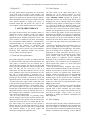
1
Proceedings of the 1999 Particle Accelerator Conference, New York, 1999
GPLS VME MODULE: A DIAGNOSTIC AND DISPLAY TOOL
FOR NSLS MICRO SYSTEMS*
S.Ramamoorthy, J.D.Smith, BNL, Upton, NY
Abstract
2.1 Interrupt Generator
The General Purpose Light Source VME module is an
integral part of every front-end micro in the NSLS control
system. The board incorporates features such as a video
character generator, clock signals, time-of-day clock, a
VME bus interrupter and general-purpose digital inputs
and outputs. This module serves as a valuable diagnostic
and real-time display tool for the micro development as
well as for the final operational systems. This paper
describes the functions provided by the board for the
NSLS micro control monitor software.
The interrupt generator on the board is capable of
generating four interrupts on the VME bus. The input pins
for the TTL level signals are on the P2 connector. Each
interrupt can be independently enabled or disabled by
software. The trigger edge (rising or falling edge of the
input signal) and the interrupt level are independently
programmable for each interrupt. All the four interrupts
can share the same level.
1 INTRODUCTION
The video section of the board can generate ASCII video
that can be displayed on a TV monitor. The board can
accept an NTSC signal from an external source and
overlay the text data onto the original signal. It uses Dual
Ported RAM that permits simultaneous VME-bus access
with video character generation. The RAM provides 4
video pages and three memory pages (4 Kbytes each) for
general- purpose use. Page selection can be done using the
slider switch at the front panel. The video memory can be
read and written at any time but only the selected page
will be displayed. The video hardware provides four
screen formats (12 lines/16 char, 12 lines/20 char, 16
lines/32 char and 16 lines/44 char). It has four
programmable color palettes. Each color palette can be set
up to one of 64 color shades (e.g. A value 0 will set the
color palette to black, 63 to white, 3 to red, 12 to green, 48
to blue and so on). Foreground or background color can be
programmed on a character by character basis. The
character generator PROM on the board can be
programmed for user-definable fonts.
The front-end computers that interface with the hardware
in the NSLS control system [1] are VME-based
microprocessor systems. The minimum requirements to
configure a system are a CPU board with Ethernet
controller (68k series: Motorola mvme162 or power PC
series: Motorola mv1603, mv1604, mv230x are used at
present), one megabyte battery-backed-up memory board
and a General Purpose Light Source board (referred to as
GPLS board). Additional boards are dictated by the
specific hardware or equipment to be controlled and/or
monitored. These systems are driven by real-time software
known as the NSLS Control Monitor [2],[3]. This paper
describes the hardware features of the GPLS board and
how the software uses the various components.
2 HARDWARE DESCRIPTION
The GPLS board in use since 1987, was originally
developed by the NSLS controls and diagnostic groups to
provide bus interrupter and ASCII video display functions.
As some of the components used by the board have
become obsolete, a new GPLS board has been redesigned
by Apogee Lab Inc.[4], following the specifications from
the NSLS controls group. The new board (Apogee Lab:
Model number VME-TVI) provides new features such as
a time code reader and generator and enhanced video
functions. The board can be accessed through an extended
(A32:D16/D08) or a standard (A24:D16/D08) address
space of a VME-bus slave interface. The main
components of the board are an interrupt generator, a
video generator, a timer module and general-purpose
inputs and outputs.
______________________________________________
*Work performed under the auspices of U.S. Dept. of Energy under the
contact no: DE-AC02-98CH10886.
0-7803-5573-3/99/$10.00@1999 IEEE.
690
2.2 Video Generator
2.3 Timer Module
The time module provides three clock signals (1kHz, 4
kHz and 250Hz) on the P2 connector and a time code
reader and generator. The time generator can be operated
in two modes. In the standalone mode, one can load Time
into the registers of the generator and start it by software.
In the synchronized mode, an external signal (amplitude
modulated 1 kHz IRIG-B carrier) is input through the P2
connector. If the IRIG-B input is lost or corrupted, the
board will free wheel and continues to provide the Time.
The Time-of-Day information can be read in three words
with one microsecond resolution.
Proceedings of the 1999 Particle Accelerator Conference, New York, 1999
2.4 Digital I/O
3.2 Video Displays
The other general purpose components are 16-bit LEDs
on the front panel, two banks of DIP switches, each
consisting of 8 switches and 32 I/O lines for parallel TTL
digital I/O (16 inputs and 16 outputs) on the P2 connector.
More information on the board can be obtained from the
user’s manual supplied by Apogee Labs Inc.[5]. A
transition module that will provide easy access to the
various signals is also available from the same company.
The video feature of the GPLS board plays a very
important role in the monitor software for micro
development as well as for the final target systems. The
simple MEMORY WRITE operation to generate an
ASCII video display is very fast and can be used as a great
debugging tool even in interrupt routines. The standard
technique of using routines to send messages to a console
(e.g. logtask in VxWorks) for diagnostic output is not
sometimes suitable in interrupt or bus exception handlers.
The system may crash even before the console output is
initiated. Also programmers may have encountered cases
where a software bug appears to have been removed by
introducing the standard printf function for debugging.
Since the console output is not synchronous with the code
being executed, one can get a false indication of the bug
location in the code when it crashes. The simple memory
write on the video page exactly locates the problem area in
the code.
The software multiplexes the first hardware page to 8
software pages. When hardware page 0 is selected, the
software will display one of the eight pages. The software
page for the display can be changed easily either by a
push-button on a panel connected to the micro or by a
remote command from any workstation in the control
system network. Both system and application tasks
generate displays for diagnostics and for continuous
monitoring of device parameters (analog read backs and
digital status). Error conditions can be highlighted in
yellow and red colors. Figures 1 to 3 show some typical
displays from the micros.
Since the board generates composite video (NTSC
signal), one can monitor the displays on the local cable TV
channels from anywhere in the lab. Some micros whose
displays are crucial for operations have dedicated TV
channels. Displays from other micros are routed through
multiplexers to two general-purpose TV channels. The
required display can be selected from any workstation.
Since these displays are generated locally, the parameter
updates are as fast as they are acquired and there is zero
loading on the network.
The hardware page 1 is used by the system task to dump
the stack registers and other pertinent information
captured when a micro encounters bus errors. Before
resetting the micro, one can get some information on the
crash from the display. Pages 2 and 3 are used by
applications to display the hardware initialization and
other diagnostics.
3 SOFTWARE INTERFACE
The control monitor software uses VxWorks which is a
commercial real-time operating system. The software
consists of a set of system tasks, interrupt handlers,
application specific modules and hardware drivers. The
system software is standard for all micros and manages
the system hardware (GPLS board, etc.), communications,
command decoding, etc. It provides system timing, and
uses real-time OS primitives to synchronize and
coordinate the activities of other tasks. This module
isolates all the kernel specifics and system hardware
interfacing from application modules and provides
services to them for real-time control.
3.1 Tasks and interrupt handlers
The system timing has a resolution of 2 milliseconds and
it is derived from the 1 kHz clock on the GPLS board. The
clock signal is connected to the first interrupt pin to
generate the timer interrupt. The monitor provides a wait
routine (equivalent to sleep call in Unix) to the application
tasks. The tasks can set a wait time as low as 2
milliseconds. The task delay (wait) does not have to rely
on the granularity of the time ticks provided by the realtime OS. A second interrupt is generated every 8
milliseconds by connecting the 250 Hz clock to the second
interrupt pin. This interrupt is used both by system and
application software to start data acquisition (e.g. reading
of ADC boards) and to signal events to other tasks. The
system provides interrupt handlers for 2 external signals
(usually from external hardware or from another micro).
The external signals are fed to the third and fourth
interrupt pins via the transition card. The handlers call the
appropriate module to service the interrupt. The levels of
these interrupts can be changed by software based on the
request from the application tasks.
The use of the GPLS board for generating timing,
periodic interrupts and servicing external interrupts has
made the software easily portable. Since the software does
not use the CPU timers, there is no conflict with the realtime kernel timing. The software has been ported to
different 68k series of CPU boards and Power PC boards
and also from the RTUX real-time OS to VxWOrks OS
with minimum changes in the system module and
absolutely no change in the application code.
691
3.3 Time stamping
The board extracts the time-of-day information from the
amplitude-modulated 1 kHz IRIG-B carrier available from
one of the outputs of a Spectracom NetCLOCk/2. This
derives time from the atomic time standard at the National
Institute of Standards and Technology via their WWVB
Proceedings of the 1999 Particle Accelerator Conference, New York, 1999
radio broadcast at 60 kHz. The system module reads the
three timer-registers every 250 milliseconds, decodes the
Time-of-Day information and makes it available to other
tasks. In addition, the time registers can be used to time a
code segment (with an accuracy of + or - 4 microseconds)
and display the value on a video page. The time data is
also used to time stamp data or an event such as an
occurrence of an alarm.
3.4 Digital I/O interface
The 16 LEDs are used for diagnostic purposes. Each task
sets up different LEDs . This provides a quick indication if
a task gets into a loop. One LED is used to generate
heartbeat signal by application tasks.
The DIP switches are used for setting up different
configurations or modes of operation. One bank of
switches is located on the board and is used to define
configurations that cannot be accidentally altered. The
front panel switches can be changed easily for the required
mode of operation. As an example, one switch is assigned
for controlling the parameter initialization during start-up.
The micros save the parameters last set by the operators
from a workstation, in the battery-backed-up memory.
When the micro reboots following a "reset", “power-on”
or "power-dip", it retrieves the battery-backed-up data for
or the default values based on the switch setting. Another
switch is used to inhibit the reporting of alarm messages.
The digital inputs and outputs are used by the
applications for various purposes. One of the outputs is
connected to the system RESET pin. Using a software
command one can initiate a system RESET. The outputs
have also been used to generate interrupts by software to
other micros or external hardware.
Figure 1. Display of radiation levels.
Figure 2. Display of XRF1 signals.
4 CONCLUSIONS
The use of the GPLS board timers for system timing and
interrupts by the software makes the porting of software to
different VME-based CPU boards and to different realtime operating systems very easy. The video display
serves as a great debugging tool during program
development. The fast display of signal values and
hardware status on TV without any load on the network
are widely used for diagnostics and general monitoring by
engineers, operators and physicists.
5 ACKNOWLEDGEMENT
The authors wish to thank Gary Frisbie for his technical
support during the testing of the boards and to Dave Grebe
of Apogee Lab for his constructive suggestions.
692
Figure 3. Display of VUV ring Parameters.
6. REFERENCES
[1] J.D.Smith, S.Ramamoorthy,Y.Tang, Nucl.Inst. and Meth.In Phys.
Res, A32 (1994) 114.
[2] S.Ramamoorthy, J.D.Smith, Proc.IEEE PAC 1993, 1849.
[3] http://www.nsls.bnl.gov/Systems/Controls.
[4] Apogee Lab Inc.,Dickerson Rd, Unit3/4, North Wales, PA19454.
[5] User’s Manual for Time/Video/Interrupt Module Model VME-TVI.