1
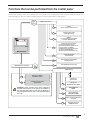
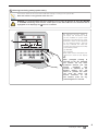
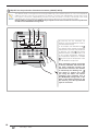
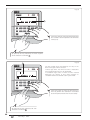
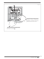
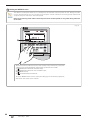
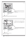
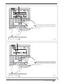
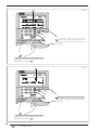
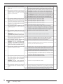
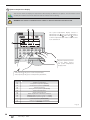
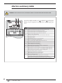
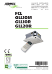
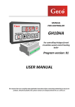
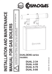
Air-cooled heat pump
USER MANUAL
HBI
GB
IHBIFY. 1101 - 6252310_01
Index
HBI control panel ................................................................................................................ 6
Control panel display ................................................................................................... 7
HBI functioning mode ........................................................................................................ 9
COOLING Mode: ......................................................................................................... 9
HEATING Mode: .......................................................................................................... 9
DOMESTIC HOT WATER PRODUCTION mode:.......................................................... 9
COOLING or HEATING +
DOMESTIC HOT WATER PRODUCTION: .................................................................... 9
Functions that can be performed from the control panel ............................................. 10
HBI control panel operational procedures ..................................................................... 11
ON/OFF due to system side functioning: .................................................................. 11
Selecting functioning mode (system water): ............................................................. 12
ON/OFF for the production of domestic hot water (HBI WT/WTS):............................ 13
Setting the work set-points: ....................................................................................... 14
Activate/Deactivate silenced mode: .......................................................................... 16
Activate/Deactivate automatic heating function: ....................................................... 17
Activate/Deactivate keys lock: ................................................................................... 18
Setting the system clock: ........................................................................................... 19
Setting the INDIVIDUAL DAY timer: ........................................................................... 21
Setting the WEEKLY timer: ......................................................................................... 25
Setting the HOLIDAYS EXCLUSION timer: ................................................................ 30
Display of the system times programs: ..................................................................... 32
Setting the timer for silenced mode: .......................................................................... 33
Setting the LEVEL 1 operational parameters: ............................................................ 36
Logic for domestic hot water production: .................................................................. 38
System temperature display: ..................................................................................... 41
Alarms summary table ..................................................................................................... 43
HBI control panel
The HBI air-cooled heat pump is
managed via a control panel with LCD
mounted on the indoor unit.
2
1
All information regarding machine
functioning and system settings are
inserted and/or displayed via this
control panel.
❊/❄
On/Off
The control panel is normally closed,
therefore its keys are not visible and
to access just open the lower door of
the panel, revealing the function keys
represented in the figure at the side.
SILENT
OPERATION MODE
HOT WATER
TEMPERATURE
ONOFF
FUNC VIEW
1 2 3 4 5 SUN MON TUE WED THU
FRI
SAT
WARNING
°C
°F
SCHEDULE
7
STATUS
1
9
2
5
11
Esc
Silent
Timer set
Temp set
❊/❄
3
13
Address
▲
▼
Function Clock set
4
15
Return
6
Key
1
2
3
4
5
6
7
8
9
Function
Unit on/off key
LCD
Go back to main display key
Key used to set the internal unit address
SILENCED mode activation key
Key used to set the operational parameters
Key used to set the TIMER function
Key used to set the system clock
Key for increasing parameter value
Key
10
11
12
13
14
15
16
17
18
8
16
Temp view
14
Set
17
10
12
18
Function
Key for decreasing parameter value
Key for setting the temperature range.
Key used to display the various system temperatures
Key used for functioning mode selection
Domestic hot water production ON/OFF key
Key used to block/release the protection for accidental
pressing of the keys
Key used to go back to previous display
Key used to confirm selections
Key used for activation of AUTOMATIC heating mode
6252310_01 - IHBIFY
GB
3
• Control panel display
The LCD with which
the control panel is
supplied,
allows
to
display all information
regarding
system
functioning or the active
settings on the unit.
A
SILENT
OPERATION MODE
1
Every
function
or
parameter is identified
by one or more icons
organised in different
groups on the basis of
the type of function to
which they refer.
2
3
HOT WATER
4
5
TEMPERATURE
6
7
B
SILENT
OPERATION MODE
2
HOT WATER
SAT
1
Function
1
2
Heating mode
2
3
4
D
Timer set
Function Clock set
1
Cooling mode
4
Automatic heating mode
Domestic hot water production mode
Temp view
STATUS
6
Anti-legionella function
7
Environment air temperature
8
4
9
HBI WT/WTS storage tank temperature
10
Solar collector temperature
GB
On
Off
On
Off
On
Off
On
Off
Flashing
On
Off
On
Off
Flashing
On
Off
On
Off
6252310_01 - IHBIFY
8
9
10
11
12
Meaning
Flashing
Temperature of the water produced by the
HBI unit
7
2
Active mode
Mode not active
Active mode
Mode not active
Could indicate that:
• the anti-freeze function is active
• the instant hot water production function is active
Active mode
Mode not active
Active mode
Mode not active
Indicates that the automatic heating mode is active during the time periods set
in the system.
Active mode
Mode not active
Indicates that the instant hot water production function is active, applied to the
production of DHW
Function active
Function not active
Indicates that the anti-legionella cycle has not been completed correctly
Indicates that a room air set is being set
Function not active
Indicates that the room air temperature function is active during the time
periods set in the system.
Indicates that a produced water set is being set
Function not active
Indicates that the produced water function is active during the time periods set
in the system.
Indicates that the temperature to be reached in the HBI WT/WTS DHW
storage tank is being set
Mode not active
Indicates that the temperature of the water produced by the solar collector (if
installed) is being set, at which the solar heating pump is to be activated
Mode not active
Flashing
A
6
❊/❄
Temp set
▲
▼
On
Off
On
Off
Flashing
5
5
2
2
Icon status
Flashing
3
C
STATUS
1
Silent
WARNING
WARNING
°C
°F
SCHEDULE
Esc
FRI
1
Silenced mode
C
TEMPERATURE
1 2 3 4 5 SUN MON TUE WED THU
B
1
A
ONOFF
FUNC VIEW
SCHEDULEAddress
Icon
10
❊/❄
D
Index
9
On/Off
FUNC VIEW
The layout at the side
summarises all icons
present on the control
panel LCD.
8
Index
Icon
Function
1
Parameters setting mode
2
Temperatures display mode
B
Index
Icon
Function
1
Alarm in progress
2
Defrost function
C
Index
Icon
Function
Icon status
On
Off
On
Off
Icon status
On
Off
On
Off
Timer function
Off
Flashing
On
Countdown function
2
Off
Flashing
On
Weekly timer
3
Off
Flashing
On
Holiday timer
4
Off
Flashing
HBI internal unit pump
5
D
HBI outdoor unit
6
7
8
1
2
Electric resistance (power level 1)
Electric resistance (power level 2)
9
DHW electric resistance
10
Thermostat
11
BMS connection system
12
Hydraulic pump on solar heating system
Meaning
Indicates that an alarm condition is in progress.
Indicates that there are no alarms active.
Indicates that the defrosting function is in progress.
Indicates that the defrosting function is not in progress.
Icon status
On
1
Meaning
Indicates that the parameters modification mode is active.
Indicates that the parameters modification mode is not active.
Indicates that the temperatures display mode is active.
Indicates that the temperatures display mode is not active.
On
Meaning
Indicates that a switch-on/off timer has been set
No timer set
Indicates that a switch-on/off timer is being set
Indicates that a countdown has been set for switch-on/off
No countdown set
Indicates that a countdown is being set for switch-on/off
Indicates that a weekly timer has been set
No timer set
Indicates that a weekly timer is being set
Indicates that a timer has been set for the holidays
No timer set
Indicates that a timer is being set for the holidays
Indicates that the hydraulic pump of the indoor unit is running
Off
Indicates that the HBI unit pump is not active.
On
Indicates that the outdoor unit is active
Off
Indicates that the outdoor unit is not active
On
Indicates that the HBI unit resistance is active at the first power level.
Off
Indicates that the HBI unit resistance is not active at the first power level.
On
Indicates that the HBI unit resistance is active at the second power level.
Off
Indicates that the HBI unit resistance is not active at the second power level.
On
indicates that the resistance in the HBI-WT/WTS DHW storage tank is active.
indicates that the resistance in the HBI-WT/WTS DHW storage tank is not
active.
Off
On
Off
Off
Indicates that the unit is managed by an external supervision system (all HBI
control panel keys will be disabled)
Indicates that the unit is not controlled via a BMS system
On
Indicates that the pump on the solar heating system unit is running
Off
Indicates that the pump on the solar heating system unit is not running
On
6252310_01 - IHBIFY
GB
5
HBI functioning mode
The HBI system is managed via the control panel on the indoor unit. This interface, as illustrated in the previous pages, allows
to select the functioning mode and set the different functions available, via the use of the keys present on the panel.
The functioning modes possible on the HBI system are:
COOLING Mode:
This is the summer functioning mode. In this mode, the HBI system can produce water at a temperature between 7°C and
30°C; however this interval can vary on the basis of the type of utility (on the basis of the presence or not of fan coils in the
system) and on the basis of the type of reference set on the panel of the indoor HBI unit (control based on the temperature
of the water produced by the indoor unit, or based on the room temperature; ATTENTION: to base the control of the
HBI system on the room temperature it is necessary to install the room air sensor or an external thermostat as
indicated in the installation manual);
The intervals within which it is possible to set the job in cooling mode are:
Reference
Temperature of water produced
Environment air temperature
Type of utility
System with fan coil
System without fan coil
All
Work temperature range
18°C ~ 25°C (default: 18°C)
7°C ~ 25°C (default: 7°C)
18°C ~ 30°C (default: 20°C)
HEATING Mode:
This is the winter functioning mode. In this mode, the HBI system can produce water at a temperature between 25°C and
55°C; however this interval can vary on the basis of the type of reference set on the panel of the indoor HBI unit (control
based on the temperature of the water produced by the indoor unit, or based on the room temperature; ATTENTION: to
base the control of the HBI system on the room temperature it is necessary to install the room air sensor or an
external thermostat as indicated in the installation manual);
The intervals within which it is possible to set the job in heating mode are:
Reference
Temperature of water produced
Environment air temperature
Type of utility
All
All
Work temperature range
25°C ~ 55°C (default: 40°C)
18°C ~ 36°C (default: 26°C)
DOMESTIC HOT WATER PRODUCTION mode:
This is the specific functioning mode for the production of DHW. In this mode the HBI system can produce water at a
temperature between 40°C and 80°C (default value 50°C).
WARNING: the indoor HBI unit does not produce DHW directly, but just hot water for heating the content of the HBI
WT/WTS storage tank (to which the anti-legionella cycle can be applied).
+
COOLING or HEATING + DOMESTIC HOT WATER PRODUCTION:
The COOLING or HEATING mode can be combined with the PRODUCTION OF DOMESTIC HOT WATER; naturally, if these
combined modes are used, the system will assign a priority to the system/domestic requests, on the basis of which the
system will satisfy first one and then the other.
WARNING: the default settings envision that the priority is assigned to the COOLING or HEATING mode, with
respect to the production of domestic hot water. Therefore, if the system receives two simultaneous requests,the
first to be satisfied will be for cooling or heating.
6
GB
6252310_01 - IHBIFY
Functions that can be performed from the control panel
Below find a summary layout of the functions that can be used via the control panel. These functions will be discussed in the
following pages one by one in order to explain how these must be used and set on HBI systems.
USER level functions
❊/❄
1
ON/OFF
due to system side functioning
2
Selecting work mode
(Heating/Cooling)
3
ON/OFF
for the production of domestic
hot water (HBI WT/WTS)
On/Off
4
INSTALLER level functions
Setting the work set-points:
(a) Room air temperature set
(b) Produced water temperature set
from the indoor unit (HBI E)
(c) Water temperature set inside the
storage tank (HBI WT/WTS)
(d) Solar collector temperature set
5
Activate/deactivate
silenced mode
6
Activate/deactivate automatic
heating function
7
Activate/deactivate keys lock
TIMER Setting
8
14
Setting the LEVEL 1
operational panels
Setting the
System clock
15
!
Displaying temperatures
of the system
WARNING: these functions have been inserted to
facilitate interventions on the unit by the installer or
the technical after-sales service. The modification of
these parameters by the user could cause damage to
the unit.
9
Setting the
INDIVIDUAL DAY TIMER
10
Setting WEEKLY
TIMER
11
Setting HOLIDAY
EXCLUSION TIMER
12
Display of the system timed
programs
13
Setting the timer for
SILENCED mode
6252310_01 - IHBIFY
GB
7
HBI control panel operational procedures
1 ON/OFF due to system side functioning:
The HBI unit allows to manage both the heating/air conditioning system (radiant panels, fan coils, low temperature
radiators) and the system for the production of domestic hot water (with HBI WT/WTS storage tank). These
two systems can function independently, therefore the HBI unit allows to activate or deactivate each mode
individually. This function allows to activate or deactivate the heating or cooling modes on the system side. Note:
the function does not set any specific mode, but activates the unit using the last work mode set.
WARNING: if a room thermostat has been installed it will no longer be possible to activate or deactivate
the HEATING or COOLING functioning mode from the control panel of the indoor HBI unit. The thermostat
will be highlighted on the display by the
icon if it is installed
!
❊/❄
On/Off
SILENT
2
OPERATION MODE
FUNC VIEW
HOT WATER
TEMPERATURE
ONOFF
1 2 3 4 5 SUN MON TUE WED THU
FRI
SAT
1
WARNING
°C
°F
SCHEDULE
1
Esc
Address
Silent
1
STATUS
2
Timer set
Temp set
▲
▼
Function Clock set
Return
In the example, a stand-by situation is taken
as the starting point (i.e. the case in which no
functioning mode is activated). The display
will show the selected temperature 1 , the
example shows the temperature of the water
inside the HBI WT/WTS storage tank, the day
of the week 2 , any information regarding
the state of the system and information
regarding time periods (if set).
❊/❄
Temp view
Set
Fig. (1)
2
2
In the example, the HEATING mode is activated
1 , represented by the relative icon;
Moreover, the temperature displayed is modified
2 passing to the output temperature from the
indoor unit (corresponding to the set work setpoint for the active mode).; Other information is
also displayed regarding the system status 3 .
In this example the information is:
- Indoor unit pump active;
- Outdoor unit active.
❊/❄
On/Off
SILENT
OPERATION MODE
HOT WATER
TEMPERATURE
1
FUNC VIEW
ONOFF
1 2 3 4 5 SUN MON TUE WED THU
FRI
SAT
WARNING
°C
°F
SCHEDULE
STATUS
3
1
Esc
Address
Silent
2
Timer set
Function Clock set
Return
Temp set
▲
▼
Set
❊/❄
Temp view
By pressing the key indicated, the HEATING or
COOLING mode is activated (deactivated).
Fig. (2)
8
GB
6252310_01 - IHBIFY
2 Selecting functioning mode (system water):
This function allows to select the work mode from heating or cooling on the system side.
Note: this selection is only possible if the unit is on.
!
WARNING: if a room thermostat has been installed it will no longer be possible to select the HEATING
or COOLING functioning mode from the control panel of the indoor HBI unit. The thermostat will be
highlighted on the display by the
icon if it is installed
❊/❄
On/Off
SILENT
OPERATION MODE
HOT WATER
TEMPERATURE
1
FUNC VIEW
ONOFF
1 2 3 4 5 SUN MON TUE WED THU
FRI
SAT
WARNING
°C
°F
SCHEDULE
STATUS
1
Esc
Address
Silent
2
Timer set
Function Clock set
Return
Temp set
▲
▼
Temp view
❊/❄
By pressing the key shown in
the figure, the functioning mode
can be modified for system water
production (the domestic hot water
production mode will be explained
on the following pages). Pressing
the key indicated will make the
functioning mode change according
to the following order:
(a) HEATING;
(b) COOLING;
Both modes will be indicated by the
relative icon shown on the display
1 .
Set
Note: prolonged pressing (5
seconds) of the key indicated,
will activate the hot water
production function just with
electric
resistance.
This
function is indicated by the
flashing
heating
icon
and
allows to produce hot water
just using the indoor unit
electric
resistance. To
exit
this function, press the key
indicated again for 5 seconds.
6252310_01 - IHBIFY
GB
9
3 ON/OFF for the production of domestic hot water (HBI WT/WTS):
The HBI unit allows to manage both the heating/conditioning system (radiant panels, fan coils, low temperature
radiators) and the system for the production of domestic hot water (with HBI WT/WTS storage tank). These
two systems can function independently, therefore the HBI unit allows to activate or deactivate each mode
individually. This function allows to activate or deactivate the domestic hot water production mode.
Note: the HBI unit cannot produce DHW directly, but produces hot water used for the successive production
of DHW via the HBI WT/WTS storage tank.
3
2
2
❊/❄
On/Off
SILENT
OPERATION MODE
HOT WATER
TEMPERATURE
1
FUNC VIEW
ONOFF
1 2 3 4 5 SUN MON TUE WED THU
FRI
SAT
WARNING
°C
°F
SCHEDULE
STATUS
1
Esc
Address
Silent
2
Timer set
Function Clock set
Return
Temp set
▲
▼
Set
Temp view
❊/❄
By pressing the key indicated, the
domestic hot water production mode is
activated (deactivated).
In the example, the HEATING mode 1
was already active and pressing the key
indicated also activates the production
of domestic hot water 3 (the priority
between DHW as system hot water is set
in the installer parameters). Moreover,
the temperature displayed is modified
2 by passing to the temperature inside
the HBI WT/WTS storage tank.
Note: prolonged pressing (5 seconds)
of the key indicated, will activate the
hot water production function just
with electric resistance. This function
is indicated by the flashing icon 3
and allows to produce hot water
just using the indoor unit electric
resistance (and eventually that of
the HBI WT/WTS storage tank, on the
basis of the relative settings). To exit
this function, press the key indicated
again for 5 seconds.
10
GB
6252310_01 - IHBIFY
4 Setting the work sets:
The HBI unit allows to manage the different parts of the system (room heating/air conditioning systems, domestic
hot water production system, solar collector, etc...). To manage the system power requests correctly, the work
set-point must be set.
These can be:
(1) (2)
(a) System temperature set-point (based on the ROOM AIR temperature)
This value indicates which temperature must be reached in the room in which the room air sensor is installed,
supplied with the HBI unit (for further information, refer to the installation manual). Once the sensor detects the
desired temperature, it will stop functioning of the HBI unit. This set-point is only visible if:
• the room air control has been set in the operational parameters;
• the room air probe accessory has been installed;
• one of the following modes is active: heating, cooling;
(1) (2)
(b) System temperature set-point (based on the PRODUCED WATER temperature)
This value indicates at which temperature functioning of the HBI unit will be stopped; the system return water
temperature value is controlled using this logic and once this value is that set, the HBI unit stops. This set-point
is only visible if:
• the return water control has been set in the operational parameters (default setting);
• one of the following modes is active: heating, cooling;
(c) HBI WT/WTS storage tank temperature set-point (domestic hot water production system)
The HBI unit can manage the request for DHW. Once it is requested, the HBI unit switches the flow from the
system to the HBI WT/WTS storage tank (acting on the 3-way diverter valve, not supplied. For further information
regarding system components necessary, refer to the installation manual) and will produce hot water until the
temperature set in this temperature set-point is reached. Once the temperature requested inside the HBI WT/
WTS storage tank has been reached, the unit will take the 3-way diverter valve towards the system. This set-point
is only visible if:
• the presence of the HBI WT/WTS storage tank has been set in the operational parameters;
• the domestic hot water production mode is active;
(d) Solar collector temperature set-point
This value indicates at what temperature the pump must be activated on the solar collector; naturally to use
this work set-point, the HBI unit must be installed on a system equipped with all components necessary for the
management of a solar collector for integration on DHW (for further information, refer to the installation manual).
This set-point is only visible if:
• the presence of a solar collector has been set in the operational parameters;
• the domestic hot water production mode is active;
(1)
the system temperature set-points based on the room air and return water temperature are in no case displayed
at the same time.
(2)
!
during the automatic heating function it will not be possible to set any temperature value to apply to the system.
WARNING: if a room thermostat has been installed it will no longer be possible to set a work set-point
from the control panel of the indoor HBI unit. The thermostat will be highlighted on the display by the
icon if it is installed.
6252310_01 - IHBIFY
GB
11
In order to set the work set-point, the HBI unit
must be on, activating the HEATING, COOLING
mode or the PRODUCTION OF DHW.
❊/❄
On/Off
SILENT
OPERATION MODE
HOT WATER
TEMPERATURE
ONOFF
FUNC VIEW
1 2 3 4 5 SUN MON TUE WED THU
FRI
WARNING
SAT
°C
°F
SCHEDULE
STATUS
1
Esc
Silent
Address
2
Timer set
❊/❄
Temp set
▲
▼
Function Clock set
Return
By pressing this key, the unit switches
on and one of the two HEATING or
COOLING modes is activated.
Temp view
Set
Se
By pressing this key, the unit switches on
and the domestic hot water production
mode is activated.
Fig. (1)
2
❊/❄
On/Off
SILENT
OPERATION MODE
FUNC VIEW
HOT WATER
TEMPERATURE
ONOFF
1 2 3 4 5 SUN MON TUE WED THU
FRI
SAT
1
WARNING
°C
°F
SCHEDULE
1
Esc
Address
Silent
3
STATUS
2
Timer set
Function Clock set
Return
Temp set
▲
▼
Set
Temp view
❊/❄
By pressing the key indicated, enter the
work set-point setting mode. Every time
this key is pressed means a move from
one set-point to the next (on the basis
of the set-points available for the work
mode active). Information is given on the
display:
• The icon that represents the currently
selected mode 1 ; which could be:
room air temperature set;
system return water temperature setpoint;
HBI WT/WTS storage tank temperature set;
solar collector temperature set;
• The icon that represents the functioning
mode 2 ;
• The current value set for the selected
set-point 3 ;
Fig. (2)
12
GB
6252310_01 - IHBIFY
Fig. (3)
❊/❄
On/Off
SILENT
OPERATION MODE
FUNC VIEW
HOT WATER
TEMPERATURE
ONOFF
1 2 3 4 5 SUN MON TUE WED THU
FRI
SAT
WARNING
°C
°F
SCHEDULE
STATUS
1
Esc
Address
Silent
2
Timer set
Function Clock set
Return
eturn
turn
Temp set
▲
▼
❊/❄
Temp view
Set
et
By pressing the ( ▲) key, the value of the
currently selected set-point is increased
(increase of 1°C every time it is pressed);
By pressing the ( ▼) key, the value of the
currently selected set-point is decreased
(decrease of 1°C every time it is pressed);
By pressing this key, the currently selected set-point value is
confirmed and the work set-point modification mode is exited.
5 Activate/Deactivate silenced mode:
The HBI unit is made up from an indoor and outdoor unit. The latter produces a determined sound level during
its normal functioning. However, a function exists that allows to lower the sound level emitted by the outdoor unit.
Note: the lowering of the sound level implies lowering of performance as the unit limits the fan speed and
the frequency of the inverter compressor.
❊/❄
On/Off
SILENT
OPERATION MODE
HOT WATER
TEMPERATURE
1
FUNC VIEW
ONOFF
1 2 3 4 5 SUN MON TUE WED THU
FRI
SAT
WARNING
°C
°F
SCHEDULE
STATUS
1
Esc
Address
Silent
2
Timer set
Function Clock set
Return
Temp set
▲
▼
❊/❄
Temp view
Set
By pressing the key shown in the figure,
the silenced mode can be activated or
deactivated; this mode is identified by
the 1 icon.
6252310_01 - IHBIFY
GB
13
6 Activate/Deactivate automatic heating function:
The HBI unit has an automatic heating function. This function allows the unit to autonomously calculate (on the
basis of a climatic curve set in the opeational parameters) the temperature of the rooms in which the room air
sensor is installed.
Note: this function can be applied only to the heating mode. It is not available for any other mode.
1
❊/❄
On/Off
SILENT
OPERATION MODE
FUNC VIEW
HOT WATER
TEMPERATURE
ONOFF
1 2 3 4 5 SUN MON TUE WED THU
FRI
SAT
WARNING
°C
°F
SCHEDULE
STATUS
1
Esc
Address
Silent
2
Timer set
Function Clock set
Return
Temp set
▲
▼
❊/❄
Temp view
Set
By pressing the key
indicated, the automatic
heating mode is activated
(or deactivated).
In the example, the
HEATING mode was
already
active
and
pressing
the
key
indicated
activates
the automatic heating
function, displaying the
relative icon 1 ;
14
GB
6252310_01 - IHBIFY
7 Activate/Deactivate keys lock:
The HBI unit allows to lock the control panel keyboard in order to prevent accidental pressing of the keys. "EE" is
shown on the display while this function is active.
❊/❄
On/Off
SILENT
OPERATION MODE
FUNC VIEW
1
HOT WATER
TEMPERATURE
ONOFF
1 2 3 4 5 SUN MON TUE WED THU
FRI
SAT
WARNING
°C
°F
SCHEDULE
STATUS
1
Esc
Address
Silent
2
Timer set
Function Clock set
Return
Temp set
▲
▼
❊/❄
Temp view
Set
Prolonged pressing (5 seconds) of the key shown in
the figure, can activate or deactivate the keys lock
function; this mode is identified by the code 1 on the
display.
6252310_01 - IHBIFY
GB
15
8 Setting the system clock:
The HBI unit control panel allows to set different types of timer. To be able to use these functions it is first
necessary to set the system clock.
Note: the system time will be kept in the memory while the unit is live (also if in stand-by), therefore after
every intervention that envisions removal of voltage from the unit it will be necessary to set the system
clock again.
Fig. (1)
❊/❄
On/Off
SILENT
OPERATION MODE
HOT WATER
TEMPERATURE
ONOFF
FUNC VIEW
1 2 3 4 5 SUN MON TUE WED THU
1
FRI
WARNING
SAT
°C
°F
SCHEDULE
STATUS
1
Esc
Silent
Timer set
Function Clock set
Address
2
Return
Temp set
▲
▼
❊/❄
Temp view
Set
By pressing the key indicated, access
system time setting. Once this key has been
pressed, the current system time will be
displayed 1 ; the characters relative to the
hours will flash.
Fig. (2)
❊/❄
On/Off
SILENT
OPERATION MODE
FUNC VIEW
HOT WATER
TEMPERATURE
ONOFF
1 2 3 4 5 SUN MON TUE WED THU
FRI
SAT
WARNING
°C
°F
SCHEDULE
1
Esc
Address
Silent
1
STATUS
2
Timer set
Function Clock set
Return
eturn
urn
Temp set
▲
▼
❊/❄
Temp view
Sett
By pressing the ( ▲) key, the system
hours increase (increase of one
hour every time it is pressed);
By pressing the ( ▼) key, the system
hours decrease (decrease of one
hour every time it is pressed);
By pressing the key indicated, the hour is confirmed and pass automatically to
setting the minutes (moreover, the characters relative to the minutes will flash 1 ).
16
GB
6252310_01 - IHBIFY
Fig. (3)
❊/❄
On/Off
SILENT
OPERATION MODE
FUNC VIEW
HOT WATER
TEMPERATURE
ONOFF
1 2 3 4 5 SUN MON TUE WED THU
FRI
SAT
1
WARNING
°C
°F
SCHEDULE
STATUS
1
Esc
Silent
2
Timer set
Temp set
▲
▼
Function Clock set
Address
Return
n
❊/❄
Temp view
Set
By pressing the ( ▲) key, the system hours
increase (increase of one minute every time it
is pressed);
By pressing the( ▼) key, the system hours
decrease (decrease of one minute every time
it is pressed);
By pressing the key indicated, the minutes are confirmed and pass automatically to
setting the day (moreover, the day icon currently selected will flash 1 ).
Fig. (4)
❊/❄
On/Off
SILENT
OPERATION MODE
FUNC VIEW
HOT WATER
TEMPERATURE
ONOFF
1 2 3 4 5 SUN MON TUE WED THU
FRI
SAT
WARNING
°C
°F
SCHEDULE
STATUS
1
Esc
Address
Silent
2
Timer set
Function Clock set
Return
n
Temp set
▲
▼
❊/❄
Temp view
Set
Pressing the ( ▲) key, pass to the next day of
the week;
Pressing the ( ▼) key, pass to the previous day
of the week;
By pressing the key indicated, the current day of the week is confirmed, exiting from the
system weekly time setting function.
6252310_01 - IHBIFY
GB
17
9 Setting the INDIVIDUAL DAY timer:
The HBI unit control panel allows to set a daily timer for automatic switch-on/off of the unit. During execution of
this time period, the unit will activate the functioning mode and the work set-point set by the user for the same
time period.
Note: The functioning mode and the work set-point set for the time period are only valid during execution
of the same.
The HBI unit envisions two different functions for the use of the time periods:
• the first follows a logic called DIRECT, i.e. the user sets a switch-on time and a switch-off time, which represent
the time period limits;
• the second follows a logic called COUNTDOWN, i.e. the user sets the start and the end of the time period,
specifying the distance (in hours) from the moment it is set;
WARNING: The setting of the INDIVIDUAL DAY timer is valid just for the day in which this function is set.
If the timer is to be repeated for several days, the WEEKLY TIMER function must be used (explained in the
next pages).
!
Fig. (1)
❊/❄
On/Off
SILENT
OPERATION MODE
FUNC VIEW
HOT WATER
TEMPERATURE
ONOFF
1 2 3 4 5 SUN MON TUE WED THU
FRI
SAT
WARNING
°C
°F
SCHEDULE
STATUS
1
1
Esc
Address
Silent
2
Timer set
Function Clock set
Return
Temp set
▲
▼
❊/❄
Temp view
Set
By pressing the key indicated, access timer setting. Every time this key is pressed,
a different icon will be displayed, representing a particular timer mode:
(1)
INDIVIDUAL DAY timer with direct logic;
(2)
INDIVIDUAL DAY timer with countdown logic;
(3)
WEEKLY timer;
(4)
HOLIDAYS EXCLUSION timer;
To set the INDIVIDUAL DAY timer function, select possibility (1) or (2); for the
remaining optionals, refer to the next section of this manual.
18
GB
6252310_01 - IHBIFY
Fig. (2)
❊/❄
On/Off
SILENT
OPERATION MODE
HOT WATER
TEMPERATURE
1
ONOFF
FUNC VIEW
1 2 3 4 5 SUN MON TUE WED THU
FRI
SAT
WARNING
°C
°F
SCHEDULE
STATUS
1
Esc
Silent
Timer set
Temp set
▲
▼
Function Clock set
Address
2
Return
rn
n
❊/❄
Temp view
Sett
These keys allow to select the
functioning mode to associate to the
time period of the timer that is being
set;
By pressing the key indicated, the functioning mode selected is confirmed 1
If there is already a daily time period on the system, pressing this key would
cause it to be deleted, taking the user to the main menu.
Fig. (3)
❊/❄
On/Off
SILENT
1
OPERATION MODE
FUNC VIEW
HOT WATER
TEMPERATURE
ONOFF
1 2 3 4 5 SUN MON TUE WED THU
FRI
SAT
WARNING
°C
°F
SCHEDULE
STATUS
1
Esc
Address
Silent
2
Timer set
Function Clock set
Return
n
Temp set
▲
▼
❊/❄
Temp view
Set
These keys allow to select the type of
automatism to associate to the time period of
the timer that is being set:
• Automatic switch-on (ON);
• Automatic switch-off (OFF);
By pressing the key indicated, the type of automatism
selected is confirmed 1
6252310_01 - IHBIFY
GB
19
Fig. (4)
❊/❄
On/Off
SILENT
OPERATION MODE
FUNC VIEW
HOT WATER
TEMPERATURE
ONOFF
1 2 3 4 5 SUN MON TUE WED THU
FRI
SAT
WARNING
1
°C
°F
SCHEDULE
STATUS
1
Esc
Silent
2
Timer set
Temp set
▲
▼
Function Clock set
Address
Return
n
❊/❄
Temp view
Set
These keys allow to select the work temperature
to associate to the time period of the timer that
is being set;
By pressing the key indicated, the work set-point
value selected is confirmed 1
Fig. (5)
1
The time setting (hours and minutes) can vary on the
basis of the type of timer selected:
• Direct logic timer; into which the time is inserted at
which the desired action is to be performed;
• Countdown logic timer; in which the time inserted
represents the amount of time (from insertion) to
countdown before the desired action is performed.
❊/❄
On/Off
SILENT
OPERATION MODE
FUNC VIEW
HOT WATER
TEMPERATURE
ONOFF
1 2 3 4 5 SUN MON TUE WED THU
FRI
SAT
WARNING
°C
°F
SCHEDULE
STATUS
1
Esc
Address
Silent
2
Timer set
Function Clock set
Return
n
Temp set
▲
▼
❊/❄
Temp view
Set
These keys allow to select the time (hours) at
which to perform the automatism associated
to the time period of the timer we are setting.
By pressing the key indicated, the time
selected is confirmed 1
20
GB
6252310_01 - IHBIFY
Fig. (6)
1
❊/❄
On/Off
SILENT
OPERATION MODE
FUNC VIEW
HOT WATER
TEMPERATURE
ONOFF
1 2 3 4 5 SUN MON TUE WED THU
FRI
SAT
WARNING
°C
°F
SCHEDULE
STATUS
1
Esc
Address
Silent
2
Timer set
Function Clock set
Return
n
Temp set
▲
▼
❊/❄
Temp view
Set
These keys allow to select the time
(minutes) at which to perform the
automatism associated to the time
period of the timer we are setting.
By pressing the key indicated, the time
selected is confirmed 1
6252310_01 - IHBIFY
GB
21
10 Setting the WEEKLY timer:
The HBI unit control panel allows to set a weekly timer for automatic switch-on/off of the unit. During execution
of these time periods (up to 5 for every day of the week) the unit will activate the functioning mode and the work
set-point set by the user for the same time period.
Note: The functioning mode and the work set-point set for the time period are only valid during execution
of the same.
Fig. (1)
❊/❄
On/Off
SILENT
OPERATION MODE
FUNC VIEW
HOT WATER
TEMPERATURE
ONOFF
1 2 3 4 5 SUN MON TUE WED THU
FRI
SAT
WARNING
°C
°F
SCHEDULE
STATUS
1
1
Esc
Address
Silent
2
Timer set
Function Clock set
Return
Temp set
▲
▼
❊/❄
Temp view
Set
By pressing the key indicated, access timer setting. Every time this key is pressed,
a different icon will be displayed, representing a particular timer mode:
(1)
INDIVIDUAL DAY timer with direct logic;
(2)
INDIVIDUAL DAY timer with countdown logic;
(3)
WEEKLY timer;
(4)
HOLIDAYS EXCLUSION timer;
To set the WEEKLY timer function, select possibility (3); for the remaining optionals,
refer to the next section of this manual.
22
GB
6252310_01 - IHBIFY
Fig. (2)
❊/❄
On/Off
SILENT
OPERATION MODE
HOT WATER
TEMPERATURE
1
ONOFF
FUNC VIEW
1 2 3 4 5 SUN MON TUE WED THU
FRI
SAT
WARNING
°C
°F
SCHEDULE
STATUS
1
Esc
Silent
Timer set
Temp set
▲
▼
Function Clock set
Address
2
Return
rn
n
❊/❄
Temp view
Sett
These keys allow to select the
functioning mode to associate to the
time period of the timer that is being
set;
By pressing the key indicated, the functioning mode selected is
confirmed 1
Fig. (3)
❊/❄
On/Off
SILENT
OPERATION MODE
FUNC VIEW
HOT WATER
TEMPERATURE
ONOFF
1 2 3 4 5 SUN MON TUE WED THU
FRI
SAT
WARNING
1
°C
°F
SCHEDULE
STATUS
1
Esc
Address
Silent
2
Timer set
Function Clock set
Return
n
Temp set
▲
▼
❊/❄
Temp view
Set
These keys allow to select the work temperature
to associate to the time period of the timer that
is being set;
By pressing the key indicated, the work set value
selected is confirmed 1
6252310_01 - IHBIFY
GB
23
Fig. (4)
❊/❄
On/Off
SILENT
OPERATION MODE
HOT WATER
TEMPERATURE
ONOFF
FUNC VIEW
1 2 3 4 5 SUN MON TUE WED THU
FRI
WARNING
SAT
°C
°F
SCHEDULE
STATUS
1
Esc
Silent
Address
2
Timer set
❊/❄
Temp set
▲
▼
Function Clock set
Return
n
Temp view
Set
Pressing the ( ▲) key, pass to the next day of
the week;
Pressing the ( ▼) key, pass to the previous day
of the week;
By pressing the key indicated, the current day of the week is confirmed
Fig. (5)
2
❊/❄
The WEEKLY timer function, envisions the possibility
of setting up to 5 daily time periods (indicated by a
progressive number on the display 2 ), every time
period envisions a start and end time, specified by the
user.
On/Off
SILENT
OPERATION MODE
FUNC VIEW
HOT WATER
TEMPERATURE
ONOFF
1 2 3 4 5 SUN MON TUE WED THU
FRI
SAT
WARNING
°C
°F
1
SCHEDULE
STATUS
1
Esc
Address
Silent
2
Timer set
Function Clock set
Return
n
Temp set
▲
▼
❊/❄
Temp view
Set
These keys allow to select the time (hours) at
which to perform the START of the time period
being set.
By pressing the key indicated, the time
selected is confirmed 1
24
GB
6252310_01 - IHBIFY
1
❊/❄
On/Off
SILENT
OPERATION MODE
FUNC VIEW
HOT WATER
TEMPERATURE
ONOFF
1 2 3 4 5 SUN MON TUE WED THU
FRI
SAT
WARNING
°C
°F
SCHEDULE
STATUS
1
Esc
Silent
Timer set
Temp set
▲
▼
Function Clock set
Address
2
Return
n
❊/❄
Temp view
Set
These keys allow to select the time (minutes) at
which to perform the START of the time period
being set.
By pressing the key indicated, the time
selected is confirmed 1
Fig. (6)
1
❊/❄
On/Off
SILENT
OPERATION MODE
FUNC VIEW
HOT WATER
TEMPERATURE
ONOFF
1 2 3 4 5 SUN MON TUE WED THU
FRI
SAT
WARNING
°C
°F
SCHEDULE
STATUS
1
Esc
Address
Silent
2
Timer set
Function Clock set
Return
n
Temp set
▲
▼
❊/❄
Temp view
Set
These keys allow to select the time (hours) at
which to perform the END of the time period
being set.
By pressing the key indicated, the time
selected is confirmed 1
Fig. (7)
6252310_01 - IHBIFY
GB
25
Fig. (8)
1
❊/❄
On/Off
SILENT
OPERATION MODE
FUNC VIEW
HOT WATER
TEMPERATURE
ONOFF
1 2 3 4 5 SUN MON TUE WED THU
FRI
SAT
WARNING
°C
°F
SCHEDULE
STATUS
1
Esc
Silent
2
Timer set
Temp set
▲
▼
Function Clock set
Address
Return
n
❊/❄
Temp view
Set
These keys allow to select the time (minutes)
at which to perform the END of the time period
being set.
By pressing the key indicated, the time
selected is confirmed 1
Fig. (9)
Once the insertion of the time period has been completed
(setting the start and end time), the system will take the
remote panel to the situation described in Fig. (5), ready to
insert the successive time period for the day selected. At
this point the user can choose whether to:
❊/❄
On/Off
SILENT
OPERATION MODE
FUNC VIEW
HOT WATER
TEMPERATURE
ONOFF
1 2 3 4 5 SUN MON TUE WED THU
FRI
SAT
WARNING
• Insert a new time period by following the procedure
illustrated by Fig.(5) up to Fig.(8) (this selection can be
made a maximum of 5 times consecutively, because the
system can manage up to 5 time periods every day);
°C
°F
SCHEDULE
STATUS
1
Esc
2
Address
Silent
2
Timer set
Function Clock set
Temp set
▲
▼
1
Return
Set
Temp view
❊/❄
• Interrupt the time periods insertion (for the day selected)
by pressing the 1 key. In this case, the system will re-start
from the window illustrated in Fig.(4) (selecting the day on
which to set the time periods) and it will be possible to set
the time periods (by repeating the operations from Fig.(5) to
Fig.(8)) for another day of the week.
• Exit the WEEKLY timer function by pressing the 2 key. In
this case, the time period settings set in the WEEKLY timer
will be activated.
26
GB
6252310_01 - IHBIFY
11 Setting the HOLIDAYS EXCLUSION timer:
The HBI unit control panel allows to temporarily exclude one or more days from those set in the WEEKLY timer
function, in a way to prevent the unit respecting the time periods when it is not necessary (for example during a
holiday period where no use is envisioned).
Note: this function does not switch the unit on or off but is limited to preventing that one or more timed
programs envisioned by the WEEKLY timer function are carried out.
!
WARNING: The setting of the HOLIDAYS EXCLUSION timer is only valid if the WEEKLY timer function has
been previously set.
Fig. (1)
❊/❄
On/Off
SILENT
OPERATION MODE
FUNC VIEW
HOT WATER
TEMPERATURE
ONOFF
1 2 3 4 5 SUN MON TUE WED THU
FRI
SAT
WARNING
°C
°F
SCHEDULE
STATUS
1
1
Esc
Address
Silent
2
Timer set
Function Clock set
Return
Temp set
▲
▼
❊/❄
Temp view
Set
By pressing the key indicated, access timer setting. Every time this key is pressed,
a different ion will be displayed, representing a particular timer mode:
(1)
INDIVIDUAL DAY timer with direct logic;
(2)
INDIVIDUAL DAY timer with countdown logic;
(3)
WEEKLY timer;
(4)
HOLIDAYS EXCLUSION timer;
To set the HOLIDAYS EXCLUSION timer function,select possibility (4);
6252310_01 - IHBIFY
GB
27
Fig. (2)
❊/❄
On/Off
SILENT
OPERATION MODE
HOT WATER
TEMPERATURE
ONOFF
FUNC VIEW
1 2 3 4 5 SUN MON TUE WED THU
FRI
WARNING
SAT
°C
°F
SCHEDULE
STATUS
1
Esc
Silent
Address
2
Timer set
Function Clock set
Return
Temp set
▲
▼
❊/❄
Temp view
Set
By pressing the key indicated, access the
setting mode for the HOLIDAYS EXCLUSION
timer function;
Fig. (3)
Once a day has been selected on which to exclude the
WEEKLY timer, the system will allow to continue to select
other days until the user presses one of the keys to exit the
1 HOLIDAYS EXCLUSION Timer function;
❊/❄
On/Off
SILENT
OPERATION MODE
FUNC VIEW
HOT WATER
TEMPERATURE
ONOFF
1 2 3 4 5 SUN MON TUE WED THU
FRI
SAT
WARNING
°C
°F
SCHEDULE
STATUS
1
Esc
1
Address
Silent
2
Timer set
Function Clock set
Temp set
▲
▼
❊/❄
Temp view
1
Return
n
Set
Pressing the ( ▲) key, pass to the next
day of the week;
Pressing the ( ▼) key, pass to the
previous day of the week;
By pressing the key indicated, the current day of the week is
confirmed. Every time this key is pressed, the current day
selected will be confirmed;
28
GB
6252310_01 - IHBIFY
12 Display of the system times programs
The HBI unit control panel allows the activation of a daily and a weekly timer. This function allows to summarise
the clock settings set on the system.
Note: this function does not modify any time setting, but only displays all settings linked to the system
timer.
Fig. (1)
❊/❄
On/Off
SILENT
OPERATION MODE
FUNC VIEW
HOT WATER
TEMPERATURE
ONOFF
1 2 3 4 5 SUN MON TUE WED THU
FRI
SAT
WARNING
°C
°F
SCHEDULE
STATUS
1
Esc
Address
By pressing the key indicated and,
HOLDING IT DOWN for 5 seconds,
access the system time programs
display. If this operation does not
generate any display it means that
no daily or weekly timings have been
inserted into the system.
Silent
2
Timer set
Function Clock set
Return
Temp set
▲
▼
❊/❄
Temp view
Set
Fig. (2)
To exit the system timed programs display
function, press one of the 2 keys;
❊/❄
On/Off
SILENT
OPERATION MODE
FUNC VIEW
HOT WATER
TEMPERATURE
ONOFF
1 2 3 4 5 SUN MON TUE WED THU
FRI
SAT
WARNING
°C
°F
SCHEDULE
STATUS
1
Esc
Address
Silent
Timer set
Function Clock set
Return
2
2
1
2
Temp set
▲
▼
❊/❄
Temp view
Set
By pressing the keys indicated, the different icons in
the 1 position will be displayed; on the basis of this
icon, it will be possible to establish to which type of
timer the data displayed refer:
INDIVIDUAL DAY (direct logic);
INDIVIDUAL DAY (countdown logic);
WEEKLY;
HOLIDAYS EXCLUSION;
6252310_01 - IHBIFY
GB
29
13 Setting the timer for silenced mode
The HBI unit control panel allows to set a timer or the silenced function.
Note: for further information regarding silenced functioning, refer to function number 5 .
Fig. (1)
❊/❄
On/Off
SILENT
OPERATION MODE
FUNC VIEW
HOT WATER
TEMPERATURE
ONOFF
1 2 3 4 5 SUN MON TUE WED THU
FRI
SAT
WARNING
°C
°F
SCHEDULE
STATUS
1
Esc
Address
Silent
2
Timer set
Function Clock set
Return
Temp set
▲
▼
❊/❄
Temp view
Set
By pressing the keys indicating and HOLDING DOWN for 5 seconds, the timer is
activated for the silenced mode.
30
GB
6252310_01 - IHBIFY
Fig. (2)
1
❊/❄
On/Off
SILENT
OPERATION MODE
FUNC VIEW
HOT WATER
TEMPERATURE
ONOFF
1 2 3 4 5 SUN MON TUE WED THU
FRI
SAT
WARNING
°C
°F
SCHEDULE
STATUS
1
Esc
Silent
2
Timer set
Temp set
▲
▼
Function Clock set
Address
Return
n
❊/❄
Temp view
Set
These keys allow to select the time
(hour) at which to perform the silenced
mode.
By pressing the key indicated, the time
selected is confirmed 1
Fig. (3)
1
❊/❄
On/Off
SILENT
OPERATION MODE
FUNC VIEW
HOT WATER
TEMPERATURE
ONOFF
1 2 3 4 5 SUN MON TUE WED THU
FRI
SAT
WARNING
°C
°F
SCHEDULE
STATUS
1
Esc
Address
Silent
2
Timer set
Function Clock set
Return
n
Temp set
▲
▼
❊/❄
Temp view
Set
These keys allow to select the time
(minutes) at which to perform the
silenced mode.
By pressing the key indicated, the time
selected is confirmed 1
6252310_01 - IHBIFY
GB
31
Fig. (4)
1
❊/❄
On/Off
SILENT
OPERATION MODE
FUNC VIEW
HOT WATER
TEMPERATURE
ONOFF
1 2 3 4 5 SUN MON TUE WED THU
FRI
SAT
WARNING
°C
°F
SCHEDULE
STATUS
1
Esc
Silent
2
Timer set
Temp set
▲
▼
Function Clock set
Address
Return
n
❊/❄
Temp view
Set
These keys allow to select the time
(hour) at which to end the silenced
mode.
By pressing the key indicated, the time
selected is confirmed 1
Fig. (5)
1
❊/❄
On/Off
SILENT
OPERATION MODE
FUNC VIEW
HOT WATER
TEMPERATURE
ONOFF
1 2 3 4 5 SUN MON TUE WED THU
FRI
SAT
WARNING
°C
°F
SCHEDULE
STATUS
1
Esc
Address
Silent
2
Timer set
Function Clock set
Return
n
Temp set
▲
▼
❊/❄
Temp view
Sett
These keys allow to select the time
(minutes) at which to end the silenced
mode.
By pressing the key indicated, the time
selected is confirmed 1
32
GB
6252310_01 - IHBIFY
14 Setting the LEVEL 1 operational parameters:
This function allows to set a series of parameters (total 27 parameters) necessary for the correct functioning of
the unit. These parameters regulate unit functioning on the basis of the type of installation carried out.
!
Index
01
WARNING: this function is dedicated to the installer of the technical after-sales staff, as it is necessary
to know the system in which the unit has been installed. The correct setting of these parameters is
NECESSARY for the correct functioning of the unit.
Description
This parameter indicates which type of
reference is used for management of the
unit;
Value
0
1
03
This parameter enables or disable the test
mode;
WARNING:
• The unit must be OFF before activating
this mode;
• If the value of this parameter is 1 or 2,
the test mode in cooling mode or in heating
mode activates, switching the unit on and
stops, switching it off. Otherwise this
stops automatically after 15 minutes of
continuous functioning;
This parameter sets the unit of measurement
for the temperature display;
04
This parameter indicates the presence of a
dedicated air thermostat;
05
This parameter enables or disables the
contemporaniety of loads (HBI unit and
electric resistance inside HBI WT/WTS
storage tank) during the production of DHW;
02
0
1
2
0
1
0
1
06
07
0
1
Anti-legionella cycle ENABLED;
0
Anti-freeze function DISABLED;
1
Anti-freeze function ENABLED;
0
0
08
1
This parameter sets the priority between
heating request and that for production of
domestic hot water, during heating mode.
The test mode is activated in HEATING mode;
This setting is to be used in the following cases:
• If commissioning takes place with outdoor air temperature over 35°C;
Unit of measurement °C (degrees Celsius);
Unit of measurement °F (degrees Fahrenheit);
Room air thermostat NOT INSTALLED;
Dedicated room air thermostat INSTALLED;
The contemporaniety of the loads is DISABLED;
This means that if the production of DHW is requested, the HBI unit will
be the only load to be used;
The contemporaniety of the loads is ENABLED;
This means that in the event of a request for the production of DHW, the
HBI unit and electric resistance inside HBI WT/WTS storage tank are
activated simultaneously;
Anti-legionella cycle DISABLED;
1
This parameter enables or disable the antilegionella cycle;
WARNING:
If theunit envisions the installation of a HBI
WT/WTS storage tank for the production
of DHW, it is mandatory to enable the antilegionella cycle;
This parameter enables or disables the
anti-freeze function. This function allows to
maintain the room temperature (room air
sensor mandatory) within a determined
safety threshold in order to prevent the room
temperature from dropping too much.
This parameter sets the priority between
cooling request and that for production of
domestic hot water, during cooling mode.
Settings
Default
Regulation based on the temperature of the water produced (this setting
is mandatory if the room air sensor or dedicated room thermostat have
0
not been installed);
Regulation based on the room temperature (this setting is ONLY possible
if the room air sensor or dedicated room thermostat have been installed);
The test mode is disabled;
The test mode is activated in COOLING mode;
This setting is to be used in the following cases:
• If necessary, top-up the refrigerant load;
• If commissioning takes place with outdoor air temperature below 10°C;
0
0
09
1
0
0
0
0
0
Priority to the cooling request. This means that during functioning in
cooling mode, the arrival of a request for the production of DHW, DOES
NOT block unit functioning, satisfying the request for DHW only after
having completed the conditioning system request.
Priority to the request for production of DHW. This means that during
functioning in cooling mode, the arrival of a request for the production of
DHW, blocks unit functioning, satisfying the request for DHW and after
having completed it, re-starts with the conditioning system request.
Priority to the heating request. This means that during functioning in
heating mode, the arrival of a request for the production of DHW, DOES
NOT block unit functioning, satisfying the request for DHW only after
having completed the heating system request.
Priority to the request for production of DHW. This means that during
functioning in heating mode, the arrival of a request for the production of
DHW, blocks unit functioning, satisfying the request for DHW and after
having completed it, re-starts with the heating system request.
6252310_01 - IHBIFY
GB
0
0
33
Index
10
11
12
13
14
15
16
Description
This parameter indicates how to manage the
electric resistance power, positioned in the
indoor unit;
Value
This parameter indicates on which day the
anti-legionella cycle must be performed (this
setting is subject to activation of the cycle
itself, set in parameter 6);
0
1
2
3
4
5
6
00
01
02
03
...
23
0
This parameter indicates the time the antilegionella cycle is to be performed, during the
day selected in the previous parameter. This
cycle will be repeated every week on the day
and at the time envisioned. The value of this
parameter can be selected within the range
of values from 00 to 23;
This parameter enables or disables the use
of the electric resistance inside the HBI WT/
WTS storage tank;
This parameter specifies the amount of
temperature probes mounted on the storage
tank.
HBI WT/WTS;
WARNING: the HBI WT/WTS accessory is
supplied with two probes; for further details
refer to the accessory installation manual;
This parameter specifies the presence or not
of the HBI WT/WTS storage tank;
This parameter specifies whether any
integrative heat sources are present;
WARNING: only using the HBI WT/WTS
accessory is it possible to envision any
integrative sources; for further details
refer to the accessory installation manual;
1
Settings
Default
Limits the electric resistance power to 50% of its nominal capacity. With
this setting, the power supplied by the electric resistance is 3 kW;
1
The electric resistance power is used at 100% of its nominal capacity.
With this setting, the power supplied by the electric resistance is 6 kW;
Set SUNDAY as the day on which to perform the anti-legionella cycle
Set MONDAY as the day on which to perform the anti-legionella cycle
Set TUESDAY as the day on which to perform the anti-legionella cycle
6
Set WEDNESDAY as the day on which to perform the anti-legionella cycle
Set THURSDAY as the day on which to perform the anti-legionella cycle
Set FRIDAY as the day on which to perform the anti-legionella cycle
Set SATURDAY as the day on which to perform the anti-legionella cycle
The anti-legionella cycle is performed at 24:00
The anti-legionella cycle is performed at 01:00
The anti-legionella cycle is performed at 02:00
23
The anti-legionella cycle is performed at 03:00
...
The anti-legionella cycle is performed at 23:00
The resistance inside the HBI WT/WTS storage tank is disabled;
The resistance inside the HBI WT/WTS storage tank is enabled and
1
switches on if the external temperature is lower than 0°C during the
production of DHW, switching off after the external unit compressor has
stopped or if the external air temperature has risen to over 2°C;
Indicates that one temperature probe has been installed;
2
Indicates that two temperature probes have been installed;
0
1
0
Indicates that the HBI WT/WTS accessory has NOT been installed
Indicates that the HBI WT/WTS accessory HAS been installed
Indicates that integrative heat sources are not envisioned;
1
Indicates that integrative heat sources are envisioned, connected to the
secondary coil of the HBI WTS storage tank;
1
2
1
This parameter specifies if fan coil terminals
have been installed in the system;
0
Indicates that fan coils have not been envisioned in the system and
supposing that the system envisions radiant panels, their use in cooling
mode could cause a condensation effect (if fed with water that is too
cold), therefore if this parameter is set at 0, the minimum value that can
be set for the water produced in cooling mode is 16°C;
Indicates that fan coil terminals are installed in the system; if a mixed fan
coil/radiant panels system is envisioned, it becomes necessary to install
a 2-way valve (piloted from the HBI unit board) on the radiant panels
line, which excludes them during functioning in cooling mode; for further
information, refer to the installation manual;
Indicates that the probe has NOT been installed
1
Indicates that the probe HAS been installed
0
17
1
18
19
This parameter specifies whether the room
air remote probe has been installed. The
room air remote probe accessory is supplied.
For further information, refer to the HBI unit
installation manual;
WARNING: the value of this parameter
must be in line with that set in parameter 1;
This parameter indicates the maximum
threshold for the water produced in heating
mode;
0
1
34
GB
6252310_01 - IHBIFY
The temperature range of the produced water is from 25°C to 55°C; this
setting is envisioned only if radiant floors are not present in the system
(in order not to allow water that is too hot feeding the radiant panels);
The temperature range of the produced water is from 25°C to 45°C; this
setting is envisioned if radiant floors are present in the system;
2
0
0
0
0
1
Index
20
21
22
23
24
25
26
27
Description
This parameter indicates what is the temperature range within which the electric
resistance is activated inside the HBI indoor unit in DHW production mode (for heating
or production of DHW);
This parameter indiates the water temperature threshold inside the HBI WT/WTS
storage tank, over which the HBI indoor unit stops heating the water, leaving the electric
resistance inside the tank to take the water to temperature set-point;
This parameter specifies the temperature at which the anti-legionella cycle will be
performed:
This parameter indicates the lower limit for the outdoor air in automatic heating mode
(for further information regarding the function, refer to function number 6 in this
manual):
This parameter indicates the upper limit for the outdoor air in automatic heating mode
(for further information regarding the function, refer to function number 6 in this
manual):
This parameter represents the differential applied to the system water or room air
temperature set-point, in cooling functioning mode;
This parameter represents the differential applied to the system water or room air
temperature set-point, in heating functioning mode;
This parameter represents the differential applied to the system water or room air
temperature set-point, for the production of hot water;
Range of values
Default
-20°C ~ 18°C
0°C
40°C ~ 50°C
50°C
40°C ~ 70°C
70°C
-20°C ~ 5°C
-15°C
10°C ~ 20°C
15°C
2°C ~ 10°C
3°C
2°C ~ 10°C
3°C
2°C ~ 8°C
3°C
Logic for domestic hot water production:
(°C)
HBI WT/WTS storage tank temperature
B
}
C
A
1
2
1
The water inside the HBI WT/WTS storage tank is
heated via the hot water produced by the indoor
unit;
2
The water inside the HBI WT/WTS storage tank is
heated via the electric resistance present in the
storage tank itself;
3
The water inside the HBI WT/WTS storage tank
is not heated;
3
2
A
Parameter 21;
B
DHW set-point:
C
Parameter 27;
6252310_01 - IHBIFY
GB
35
1
2
ONCE THE UNIT IS INSTALLED, MAKE SURE
THAT ALL OPERATIONAL PARAMETERS ARE
SET CORRECTLY.
❊/❄
On/Off
SILENT
OPERATION MODE
HOT WATER
TEMPERATURE
ONOFF
FUNC VIEW
1 2 3 4 5 SUN MON TUE WED THU
FRI
The function allows to modify the parameters
indicated in the previous tables. Every
parameter will be identified by an index 1 and
a value 2 on the panel display. The first is found
in the previous tables and used to identify the
meaning of the parameter, the other determines
the value at which it is currently set.
WARNING
SAT
°C
°F
SCHEDULE
STATUS
1
Esc
Address
Silent
2
Timer set
❊/❄
Temp set
▲
▼
Function Clock set
Return
Temp view
Set
By pressing the key shown in the figure, access
the LEVEL 1 installer parameters setting menu;
Fig. (1)
Fig. (2)
1
❊/❄
On/Off
SILENT
OPERATION MODE
FUNC VIEW
HOT WATER
TEMPERATURE
ONOFF
1 2 3 4 5 SUN MON TUE WED THU
FRI
SAT
WARNING
°C
°F
SCHEDULE
STATUS
1
Esc
Address
Silent
2
Timer set
Function Clock set
Return
n
Temp set
▲
▼
❊/❄
Temp view
Sett
Pressing the ( ▲) key, pass to the
next parameter;
Pressing the ( ▼) key, pass to the
previous parameter;
By pressing the key indicated, enter the
modification mode for the parameter selected 1
36
GB
6252310_01 - IHBIFY
Fig. (3)
1
❊/❄
On/Off
SILENT
OPERATION MODE
FUNC VIEW
HOT WATER
TEMPERATURE
ONOFF
1 2 3 4 5 SUN MON TUE WED THU
FRI
SAT
WARNING
°C
°F
SCHEDULE
STATUS
1
Esc
Silent
2
Timer set
Temp set
▲
▼
Function Clock set
Address
Return
n
❊/❄
Temp view
Sett
Pressing the ( ▲) key, increase the
parameter value;
Pressing the ( ▼) key, decrease the
parameter value;
By pressing the key indicated, the parameter
value selected is saved 1
Fig. (4)
❊/❄
On/Off
SILENT
OPERATION MODE
FUNC VIEW
HOT WATER
TEMPERATURE
ONOFF
1 2 3 4 5 SUN MON TUE WED THU
FRI
SAT
WARNING
°C
°F
SCHEDULE
STATUS
1
1
Esc
Address
Silent
2
Timer set
Function Clock set
Temp set
▲
▼
❊/❄
Once the operations described in Fig.3 have
been completed, the panel goes back to
the situation described in Fig.2 (parameter
selection). From here it will be possible to select
a new parameter and modify it in the same way
in which the previous one was modified, until
one of the two keys indicated in 1 have been
pressed, to exit the LEVEL 1 installer parameters
modification function;
Temp view
1
Return
Set
6252310_01 - IHBIFY
GB
37
15 System temperature display:
This function allows to display the temperatures detected by the different unit probes. This information can be
used by the installer or technical after-sales staff to evaluate unit functioning
!
WARNING: This function is dedicated to the installer or technical after-sales assistance staff.
2
3
The system temperatures display function is
indicated by the 1 icon; every temperature is
indicated by an index 2 and a value 3 . To know
to which temperature each index is referred, refer
to the table below.
❊/❄
On/Off
SILENT
OPERATION MODE
FUNC VIEW
HOT WATER
TEMPERATURE
ONOFF
1 2 3 4 5 SUN MON TUE WED THU
FRI
1
SAT
WARNING
°C
°F
SCHEDULE
STATUS
1
Esc
Address
Silent
2
Timer set
Function Clock set
Return
Temp set
▲
▼
❊/❄
Temp view
Set
By pressing the key shown
in the figure, access
the system temperature
display menu.
Pressing the ( ▲) key, pass to the next parameter;
Pressing the ( ▼) key, pass to the previous parameter;
Index
01
02
03
04
05
06
07
08
09
10
11
12
13
Temperature
Outdoor air temperature
Compressor temperature (INTAKE)
Compressor temperature (PRESSING)
Defrost temperature
Cooling circuit temperature (LIQUID SIDE)
Water inlet temperature
Water outlet temperature
Water temperature in the electric resistance
STORAGE TANK temperature (probe 2 = LOWER)
STORAGE TANK temperature (probe 1 = UPPER)
Room temperature (ROOM PROBE)
Cooling circuit temperature (GAS SIDE)
NOT USED
Fig. (1)
38
GB
6252310_01 - IHBIFY
❊/❄
On/Off
SILENT
OPERATION MODE
FUNC VIEW
HOT WATER
TEMPERATURE
ONOFF
1 2 3 4 5 SUN MON TUE WED THU
FRI
SAT
WARNING
°C
°F
SCHEDULE
STATUS
1
Esc
Address
Silent
2
Timer set
Function Clock set
Return
Temp set
▲
▼
❊/❄
Temp view
Set
By pressing the key shown
in the figure, escape the
function by displaying the
temperatures and return to
the main menu.
By pressing the key shown in the figure, escape the
function by displaying the temperatures and return to the
main menu.
Fig. (2)
6252310_01 - IHBIFY
GB
39
Alarms summary table
!
WARNING: In the event of an error, consult the installer or technical after-sales assistance staff.
1
2
If an alarm condition should occur, it is signalled on the remote panel
display, via the general attention icon 2 , and the icon 1 that represents
the error code. To establish the cause, refer to the error code table given
below;
❊/❄
On/Off
SILENT
OPERATION MODE
FUNC VIEW
HOT WATER
TEMPERATURE
ONOFF
1 2 3 4 5 SUN MON TUE WED THU
FRI
SAT
WARNING
°C
°F
SCHEDULE
STATUS
1
Esc
Address
Silent
2
Timer set
Function Clock set
Return
Temp set
▲
▼
❊/❄
Temp view
Set
Error
code
F4
F6
F7
F5
EF
E5
E1
E3
E4
C5
E6
Fc
F9
dH
F1
F8
FE
FL
F3
dF
F0
Ec
E2
EH
40
GB
6252310_01 - IHBIFY
Cause of the error
Outdoor air temperature probe malfunctioning (outdoor unit)
Probe malfunctioning for the defrosting function
Probe malfunctioning on the compressor pressing line
Probe malfunctioning on the compressor intake line
Outdoor unit fan malfunctioning
Compressor load protection error/Inverter driver malfunction
High pressure alarm
Low pressure alarm
High temperature alarm on the pressing line
Indoor unit management malfunctioning
Communication error between indoor and outdoor unit
High pressure switch malfunctioning
Water outlet probe malfunctioning
Water outlet probe malfunctioning (2)
Malfunctioning of the temperature probe on the liquid line
Water inlet probe malfunctioning
Malfunctioning on probe number 2 on the HBI WT/WTS storage tank
Malfunctioning on probe number 1 on the HBI WT/WTS storage tank
Malfunctioning of the temperature probe on the gas line
Integrative heating systems output error
Malfunctioning of the room air remote probe
Malfunctioning of the 3-way diverter valve
Indoor unit anti-freeze alarm
First stage malfunctioning of the HBI indoor unit resistance
Second stage malfunctioning of the HBI indoor unit resistance
Malfunctioning of the HBI WT/WTS storage tank electric resistance
The technical data given in this documentation are not binding.
AERMEC S.p.A. reserves the right to apply all the modifications deemed necessary for improving the product at any time.
Les données mentionnées dans ce manuel ne constituent aucun engagement de notre part. Aermec S.p.A. se réserve le droit de modifier à tous moments les
données considérées nécessaires à l’amelioration du produit.
Technical data shown in this booklet is not binding.
Aermec S.p.A. shall have the right to introduce at any time whatever modifications deemed necessary to the improvement of the product.
Im Sinne des technischen Fortsschrittes behält sich Aermec S.p.A. vor, in der Produktion Änderungen und Verbesserungen ohne Ankündigung durchzuführen.
Los datos técnicos indicados en la presente documentación no son vinculantes.
Aermec S.p.A. se reserva el derecho de realizar en cualquier momento las modificaciones que estime necesarias para mejorar el producto.
AERMEC S.p.A
I-37040 Bevilacqua (VR) - Italia
Via Roma, 996 - Tel. (+39) 0442 633111
Telefax (+39) 0442 93730 - (+39) 0442 93566
www .aermec. com - info @ aermec. com