1
Operating instructions
For the operator
Operating instructions
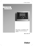
VRC 470f
Weather compensator with radio data
transmission
GB, IE
Table of contents
Table of contents
1
1.1
1.2
1.3
1.4
1.5
1.6
1.7
Notes on the operating instructions.................. 3
Observing other applicable documents ................ 3
Document storage ...................................................... 3
Symbols used ............................................................... 3
Identification plate ..................................................... 3
Applicability of the instructions .............................. 3
CE label ......................................................................... 3
Glossary......................................................................... 3
2
2.1
2.1.1
2.1.2
2.2
2.3
Safety ............................................................................4
Safety and warning information .............................4
Classification of warnings .........................................4
Structure of warnings ................................................4
Intended use ................................................................4
Basic safety instructions...........................................4
3
3.1
3.2
3.3
3.3.1
3.3.2
3.3.3
3.3.4
Description of the appliance .................................6
Appliance design .........................................................6
Functionality.................................................................6
Operating levels .......................................................... 7
Menu structure design .............................................. 7
Basic display ................................................................8
Selection levels............................................................9
Setting level .................................................................9
4
4.1
4.1.1
4.1.2
4.2
4.3
4.3.1
4.3.2
Operation ................................................................... 10
Operating concept .................................................... 10
Operation in the basic display ............................... 10
Operation via function keys .....................................11
Overview of menu structure ...................................12
Overview of setting and read-out options ...........15
Overview of operating modes ................................15
Overview of operating levels ..................................16
5
5.1
5.1.1
5.1.2
5.1.3
5.1.4
5.1.5
5.1.6
5.1.7
5.1.8
5.1.9
5.1.10
5.1.11
5.1.12
5.1.13
5.1.14
5.1.15
Description of functions ...................................... 20
Functions.................................................................... 20
Reading information ............................................... 20
Setting desired temperatures .................................21
Setting timer programmes .....................................22
Days away from home scheduling ........................24
Days at home scheduling ........................................24
Language selection ..................................................24
Setting the time ........................................................24
Setting the date .......................................................24
Changing over to daylight saving time ...............25
Setting the display contrast ...................................25
Setting the offset room temperature ..................25
Setting the offset outside temperature ..............25
Changing heating circuit naming ..........................25
Restoring factory settings ......................................25
Installer level..............................................................26
2
5.2
5.2.1
5.2.2
5.3
5.3.1
5.3.2
5.3.3
5.3.4
5.3.5
6
6.1
6.2
6.3
6.3.1
6.3.2
Operating modes ......................................................26
Operating modes for the heating circuit ............26
Operating modes for hot water production
and circulation ...........................................................27
Advanced functions..................................................29
Cylinder boost............................................................29
Party function ............................................................29
1 Day away from home ........................................... 30
1 day at home ............................................................ 30
Ventilation boost...................................................... 30
6.3.3
Service and troubleshooting ................................31
Service ..........................................................................31
Cleaning the controller.............................................31
Detecting and rectifying faults ...............................31
Display remains dark ...............................................32
Error message "Clean outside temperature
sensor/transmitter" ..................................................32
Error message "Replace battery".........................33
7
Energy-saving tips .................................................34
8
8.1
8.2
Warranty and customer service.........................35
Vaillant warranty .......................................................35
Vaillant Service..........................................................35
9
9.1
9.2
Decommissioning ....................................................36
Replacing the controller..........................................36
Recycling and disposal ............................................36
10
Technical data ..........................................................37
11
Glossary .....................................................................38
Index
.................................................................................... 40
Operating instructions VRC 470f 0020124644_00
Notes on the operating instructions
1
Notes on the operating instructions
These operating instructions are intended for the operator of the heating system. No particular prior knowledge
is required.
1.1
Observing other applicable documents
When operating the VRC 470f controller, always take
note of all operating instructions that are supplied with
the other components of the heating system.
1.2
Document storage
Keep these operating instructions and all other applicable documents safe so that
– they are available whenever required,
– they are kept for the full service life of the appliance,
– they are available to all subsequent operators.
1.3
1.5
1
Applicability of the instructions
These operating instructions apply to appliances with
the following article numbers only:
Type designation
Article number
Country
VRC 470f
0020108137
GB, IE
Tab. 1.1
Type overview
The 10-digit article number can be found in the serial
number of the appliance. The article number is found in
the second line of the serial number. You can view the
serial number under "Menu ¬ Information ¬ Serial
number" (¬ Fig. 4.10).
1.6
CE label
The CE label certifies that the VRC 470f complies with the fundamental requirements of the
applicable directives.
Symbols used
The symbols used in the text are explained below:
i
>
1.4
Useful instructions and information
1.7
Required actions
Glossary
Technical terms are explained in the glossary (¬ Section 11) at the end of these instructions.
Identification plate
The identification plate is located on the rear panel of
the controller casing.
Operating instructions VRC 470f 0020124644_00
3
2 Safety
2
Safety
2.1
2.2
Safety and warning information
> When operating the VRC 470f controller, take account
of the general safety instructions and the warning
notes that appear before all of the actions.
2.1.1
Classification of warnings
The warning notes are classified in accordance with the
severity of the possible danger using the following danger signs and signal words:
Danger sign Signal
word
a
e
a
b
2.1.2
Danger!
Explanation
Immediate risk of fatal
injury or risk of severe
damage to property
Danger!
Risk of death from electric
shock
Warning!
Risk of minor personal
injury
Risk of material or environmental damage
Structure of warnings
Warning signs are identified by an upper and lower separating line and are laid out according to the following
basic principle:
a
4
The VRC 470f controller is a state-of-the-art device
manufactured in accordance with recognised safety regulations.
Even so, in the event of inappropriate or non-intended
use, damage to the appliance and other property may
arise.
The VRC 470f controller controls a Vaillant heating system based on outside temperature and programmed timings. The controller is connected to a Vaillant boiler.
The controller can also regulate the hot water production of a connected domestic hot water cylinder with or
without circulation.
You should only remove the controller temporarily from
the wall-mounting base, e.g. to adjust the settings. Apart
from that, you should always operate it in conjunction
with the wall-mounting base.
Any other or additional use is considered to be improper.
The manufacturer/supplier is not liable for any resulting
damage. The owner alone bears any risk.
Follow the operating instructions
Proper use also includes compliance with the operating
instructions and all other applicable documents.
2.3
Caution!
Signal word!
Type and source of danger!
Explanation of the type and source of danger
> Measures for averting the danger
Intended use
Basic safety instructions
Installation of the device can be only carried out by a
heating engineer. This heating engineer is also responsible for proper installation and start-up.
Protecting from Legionella
The controller is furnished with an anti-Legionella function to protect against infection by germs (Legionella).
When the anti-Legionella function is activated, the water
in the domestic hot water cylinder is heated to over
60 °C for at least an hour. The heating engineer activates the anti-Legionella function on installation of the
controller.
> Ask the heating engineer if he has activated the antiLegionella function.
> Ask the heating engineer to explain how the antiLegionella function works.
Operating instructions VRC 470f 0020124644_00
Safety 2
Preventing the risk of scalding
There is a danger of scalding at the hot water draw-off
points when the target temperatures are in excess of
60 °C. Young children and elderly persons can be at risk
from scalding at lower temperatures.
> Select a moderate target temperature.
> If the anti-Legionella function is activated, discuss the
following with the heating engineer:
– when does the anti-Legionella function start,
– when will the hot water cool back down to the target temperature,
– is a mixing valve incorporated in the heating system as protection against scalding,
– what do you have to do to avoid scalding.
Preventing a malfunction
> Only operate the heating installation when it is in a
technically perfect condition.
> Ensure that any faults and damage that affect safety
are rectified immediately.
Preventing frost damage
If there is a power cut, or if the room temperature is set
too low in individual rooms, sections of the heating system might be damaged by frost.
> If you are absent during a frosty spell, ensure that the
heating system remains in operation and the rooms
are warmed adequately.
> Observe the frost protection instructions (¬ Section 3.2).
Operating instructions VRC 470f 0020124644_00
5
3 Description of the appliance
3
Description of the appliance
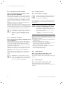
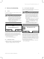
3.1
Appliance design
1
3
1
2
4
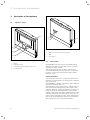
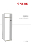
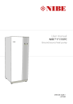
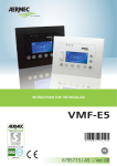
Fig. 3.2
Front view of radio receiver unit
3
2
Fig. 3.1
1
Diagnostic socket for the heating engineer
2
LED
3
Teach button
Front view of VRC 470f radio controller
3.2
1
Display
2
Right function key
3
Control knob (without pushbutton function)
4
Left function key
Functionality
The VRC 470f controller controls the Vaillant heating
system and production of hot water from a connected
domestic hot water cylinder.
Your heating engineer will install the controller in a
room within the living area of your home. You will then
be able to control the heating and hot water systems
from that room.
Heating installation
You can use the controller to set different desired temperatures for different times of the day and for different
days of the week.
The VRC 470f is a weather compensator with a temperature sensor mounted outdoors.
The temperature sensor measures the outside temperature and sends the information by radio signal to the
controller. When the outside temperature is low, the controller increases the flow temperature of the Vaillant
heating system. When the outside temperature rises, the
controller reduces the flow temperature. Thus, the controller reacts to fluctuations in the outside temperature
and, via the flow temperature, keeps the room temperature constantly at the set desired temperature.
6
Operating instructions VRC 470f 0020124644_00
Description of the appliance 3
The frost protection function protects the heating system and dwelling against frost damage.
The frost protection function monitors the outside temperature. If the outside temperature:
– falls below 3 °C, the controller switches the boiler on
after a frost protection delay time, and brings the
room temperature to 5 °C.
– rises above 4 °C, the controller does not switch the
boiler on but monitors the outside temperature.
i
The heating engineer will set the frost protection delay time at the time of installation.
Preparation
With the VRC 470f controller, you can also set the temperature and timings for hot water production. The
boiler heats the water in the domestic hot water cylinder
to the set temperature. You can set a period during
which hot water should be available in the domestic hot
water cylinder.
If a circulation pump is installed in the heating system,
you can set a period for circulation. During the set
period, hot water circulates from the domestic hot water
cylinder to the water taps and back to the domestic hot
water cylinder. If, for example, you turn on a water tap
during this time, hot water will come out of the tap
immediately.
Hot water production is not affected by the weather
compensated control of the heating system.
Several heating circuits
The controller can control two heating circuits:
– two heating circuits independently of each other, e.g.
"HEATING 1" in a single occupancy house and "HEATING 2" in a granny annexe in this house.
– two heating circuits interdependent on each other in
a dwelling, e.g. "HEATING 1" for radiators and "HEATING 2" for underfloor heating.
3.3
Operating levels
The controller has two superordinate operating levels.
Operating level for the heating engineer
The operating level for the heating engineer must only
be operated with expertise and is therefore protected by
a code. This level is used by the heating engineer to
adjust the controller to the heating system.
Operating level for the operator
The operating level for the operator shows you important information and offers set-up options which do not
require any special prior knowledge. Via a menu structure, you can access configurable or read-only values.
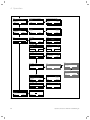
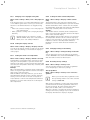
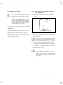
3.3.1
Menu structure design
A
1
2
1
2
4
3
4
4
4
1
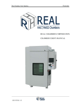
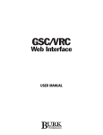
Fig. 3.3
3
Menu structure
A
Basic display
1
Selection level 1
2
Selection level 2
3
Selection level 3
4
Setting level
The menu structure of the controller is split into four
levels. From the basic display, you can access selection
level 1. Through up to three selection levels, you can
access one level lower or higher in the menu structure.
The setting level is accessed from the lowest selection
level.
Operating instructions VRC 470f 0020124644_00
7
3 Description of the appliance
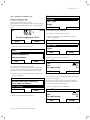
3.3.2
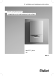
Basic display
The controller is battery-powered. To save power and so
extend the life of the batteries, the display is normally
switched off. If you press one of the function buttons or
turn the control knob, the backlighting switches on and
the basic display appears. At this point, you have not
changed any settings. Only if you press one of the function buttons or turn the control knob when the display is
switched on are the settings changed.
1
8
2
Auto
7
10:02
13,5°C
19,5
°C
3
Desired temperature 20,0°C
6
Menu
Mode
4
5
i
The backlighting goes out approx. 10 seconds
after the last operation. The display switches
off approx. 1 minute after the last operation.
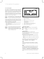
The basic display shows the current settings and values
of the heating system. If you make a setting on the controller, the display on the screen switches from the basic
display to the display for new settings.
The basic display appears when you:
– press a button or turn the control knob when the display is switched off.
– press the left function key and thus exit selection
level 1.
i
If your heating system has two independent
heating circuits, the heating engineer will
determine during installation whether or not
the basic display shows the values of heating
circuit 1 or heating circuit 2.
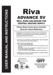
Fig. 3.4
1
2
3
4
5
6
7
8
Basic display
Outside temperature
Current room temperature
Time
Current function of the right function key
(Soft key function)
Current function of the left function key
(Soft key function)
Desired temperature (target room temperature)
Symbol for heating mode in "Auto" mode
Mode set for the heating mode
Heating mode symbols
Sun = Heating mode within a set period (Comfort
mode)
Moon = Heating mode outside a set period (Night
mode)
Soft key function
Both function keys have a soft key function.
The current functions of the function keys are displayed
in the lower display line.
Depending on the selection level selected in the menu
structure, the list entry or the value:
– the current function (5) of the left function key may
differ.
– the current function (4) of the right function key may
differ.
If, for example, you press the left function key, the current function of the left function key switches from
"Menu" (¬ Fig. 3.4) to "Back" (¬ Fig. 3.5).
Menu
If you press the left function key "Menu", you switch
from the basic display to selection level 1 of the menu
structure.
Mode
If you press the right function key "Mode", you access
the settings under "Mode" directly from the basic display. In this way, you can quickly change the mode of
"HEATING 1" or "HEATING 2" (¬ Section 4.3.1). Whether
or not you can change a heating circuit depends on the
settings made by the heating engineer during installation.
8
Operating instructions VRC 470f 0020124644_00
Description of the appliance 3
Desired temperature
Depending on the mode, the desired temperature (6)
may be greyed out on the display. This is the case, for
example, in "Summer mode". As heating is not operational in "Summer mode", and therefore the heating circuit is off, there is no desired temperature.
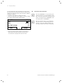
3.3.3
Selection levels
Through the selection levels, you navigate to the setting
level in which you wish to read or change settings.
The selection levels have four display fields.
3.3.4
Setting level
In the setting level, you can select the values you wish to
read or change.
i
The controller must first retrieve the data
from the radio receiver unit. Normally, the
retrieval process takes up to two seconds.
During that time, the display shows dashes
(--) instead of figures.
The setting level has five display fields.
1
HEATING 1
Day
Night set-back
4
1
Menu
Information
Desired temperatures
Time programmes
3
Back
2
5
Back
Select
Display fields in the selection levels
1
Scroll bar (only appears if there are more list entries than
can be shown at once on the display)
2
Current functions of the right and left function keys (soft
key functions)
3
List entries of the selection levels
4
Current function or selection level
Operating instructions VRC 470f 0020124644_00
Change
3
4
Fig. 3.6
2
Fig. 3.5
20,0°C
7,5°C
Display fields in the setting level
1
Current selection level
2
Values
3
Highlighting (white font on black background) shows the
current selection.
4
Current functions of the right and left function keys (soft
key functions)
5
Setting level
9
4 Operation
4
4.1
Operation
Operating concept
4.1.1
From the basic display, you can change the "Desired day
temperature" directly for the current day by turning the
control knob.
The controller is operated with two function keys and a
control knob (¬ Section 3.1).
Use the function keys to:
– navigate through the selection levels and the setting
level in the menu structure (¬ Tab. 4.2),
– highlight a setting,
– confirm a value,
– activate a mode,
– cancel changing a value.
Use the control knob to:
– navigate through the list entries of a selection level
by turning the control knob to the left or right
– highlight a selection level or a setting level,
– change a selected value.
The display shows a highlighted selection level, a setting
level or a highlighted value with white font on a black
background.
Operation in the basic display
Desired day temperature
Only today: 18°C
For Permanent Change
Press Ok
Ok
Fig. 4.1
Request to change the desired temperature
In the display, a request appears asking if you wish to
change the "Desired day temperature" for the current
day or on a permanent basis.
To change the "Desired day temperature" for the current day only:
> Turn the control knob to set the desired temperature.
The display switches back to the basic display after 12
seconds. The set desired temperature applies only until
the end of the active period of the current day.
To change the "Desired day temperature" permanently:
> Turn the control knob to set the desired day temperature.
> Press the right function key "OK".
The display switches to the basic display. The new
desired day temperature is applied permanently.
10
Operating instructions VRC 470f 0020124644_00
Operation 4
4.1.2
Operation via function keys
Example: changing the time
You wish to change the time.
The display shows the basic display.
If the display does not show the basic display, press the
left function key "Back" until the basic display appears
again.
Day
08:15
13,5°C
19,5 °C
Mode
Fig. 4.2 Basic display
> Press the left function key "Menu".
Menu
Information
Desired temperatures
Time programmes
Back
Select
Fig. 4.5 Selection level 2: "Language"
> Turn the control knob until the "Date / Time" list
entry is highlighted.
Basic settings
Language
Date / Time
Display
Back
Select
Fig. 4.6 Selection level 2: "Date / Time"
> Press the right function key "Select".
Select
Fig. 4.3 Selection level 1: "Information"
The controller is now in selection level 1.
The left function key now has the function "Back" (to
the next selection level up), the right function key has
the function "Select" (the next selection level down).
> Turn the control knob until the "Basic settings" list
entry is highlighted.
Menu
Day away from home scheduling
Day at home scheduling
Basic settings
Back
Back
The controller is now in selection level 2.
Desired temperature 20,0°C
Menu
Basic settings
Language
Date / Time
Display
Select
Fig. 4.4 Selection level 1: "Basic settings"
> Press the right function key "Select".
Date / Time
Time
Date
Day-light savings
Back
Fig. 4.7
08 :15
01.01.10
Off
Change
Setting level: figure for hours is highlighted
The controller is now in setting level "Time". The value
for hours is highlighted.
The left function key now has the function "Back" (to
the next selection level up), the right function key has
the function "Change" (of the value).
> Press the right function key "Change".
Date / Time
Time
Date
Day-light savings
Back
08 :15
01.01.10
Off
Change
Fig. 4.8 Setting level: alteration of figure is enabled
Operating instructions VRC 470f 0020124644_00
11
4 Operation
You can change the value by turning the control knob.
The left function key now has the function "Cancel" (the
change), the right function key has the function "OK" (to
confirm the change).
> Turn the control knob to change the value.
> Press the right function key, "OK", to save the change.
The controller has saved the changed time.
Date / Time
Time
Date
Day-light savings
Back
Fig. 4.9
09 :15
01.01.10
Off
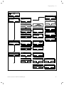
4.2
Overview of menu structure
i
List entry "HEATING 2" is only shown by the
controller if there is a second heating circuit.
Two consecutive display texts mean that there
can be one display text for "HEATING 1" and
one display text for "HEATING 2".
i
Greyed out display texts are only shown by
the controller if a corresponding expansion
module is connected. Ask the heating engineer which expansion modules are installed.
Change
Setting level: change has been saved
> Press the left function key "Back" several times to
switch back to the next selection level up and to
access the basic display from selection level 1.
12
Operating instructions VRC 470f 0020124644_00
Operation 4
Auto
1:02
13,5°C
19,5
°C
Desired temperature 20,0°C
Menu
Menu
Information
Desired temperatures
Time programmes
Back
System
Status
Water pressure
Domestic hot water
Mode
Information
System status
Solar yield
Contact details
Select
Back
Back
Menu
Information
Desired temperatures
Time programmes
Back
Back
Back
Menu
Information
Desired temperatures
Time programmes
Back
Select
Back
Select
Select
7 8 9 10 11 12
Select
HEATING 1
away to
At home from
At home to
Back
Back
Back
Cancel
Back
Back
Back
03.04.10
24.12.10
26.12.10
Back
Back
20,0°C
15,0°C
Change
Change
43°C
Ok
06 : 00 - 22 : 00
__:__-__:__
__:__-__:__
Select
Select
Monday
Period 1:
Period 2:
Period 3:
Select
Back
Back
Monday
Period 1:
Period 2:
Period 3:
Domestic hot water
Preparation
Circulation
Back
17°C
22:10
01.02.10
Back
Back
Domestic hot water
Preparation
Circulation
Select
HEATING 1
HEATING 1---------------------------------Day temperature
20,0°C
Night temperature
7,5°C
HEATING 1
Room temperature
Auto day temp until
away from
Back
Monday
Period 1:
Period 2:
Period 3:
Select
Back
Back
Back
Domestic hot water
Domestic hot water
Time programmes
HEATING 1
HEATING 2
Domestic hot water
Back
6
HEATING 1
Day
Night set-back
Time programmes
HEATING 1
HEATING 2
Domestic hot water
Select
4 5
123456
7890123456
7890123456
Desired temperatures
HEATING 1
HEATING 2
Domestic hot water
Back
3
Serial number
Desired temperatures
HEATING 1
HEATING 2
Domestic hot water
Select
2
Back
Contact details
Installer
Phone
Select
76°C
4500kWh
No
00000
1
Select
Information
Solar yield
Contact details
Serialnummer
Back
0001
kWh
2010
2011
Information
Systemstatus
Solar yield
Contact details
Back
System
Collector temp
Solar yield
Reset solar yield
Select
Information
System status
Solar yield
Contact details
Back
Fault
2,3bar
Charged
Select
Back
Back
05 : 30 - 22 : 00
__:__-__:__
__:__-__:__
Select
Select
06 : 00 - 22 : 00
__:__-__:__
__:__-__:__
Select
Select
Fig. 4.10 Overview of menu structure part 1
Operating instructions VRC 470f 0020124644_00
13
4 Operation
Menu
Days away from home scheduling
Days at home scheduling
Basic settings
Back
Select
Menu
Days away from home scheduling
Days at home scheduling
Basic settings
Back
Select
Menu
Days away from home scheduling
Days at home scheduling
Basic settings
Back
Select
Days away from home scheduling
HEATING 1
HEATING 2
Back
Select
Days at home scheduling
HEATING 1
HEATING 2
Back
Days away from home scheduling
Start
01. 02. 10
End
03. 04. 10
Temperature
15,0°C
Back
Back
Change
Change
Days at home scheduling
Start
End
Select
Basic settings
Language
Date / Time
Display
Back
Back
24. 12. 10
26. 12. 10
Change
Change
Language
English
Back
Select
Basic settings
Language
Date / Time
Display
Back
Date / Time
Time
Date
Day-light savings
Back
Select
Back
Display
Display contrast
Offset room temp
Offset outside temp.
Basic settings
Language
Date / Time
Display
Back
Select
Basic settings
Mode
Change heating circuit naming
Factory reset
Back
Select
Back
OK
01: 02
10. 03. 04
Off
Change
11
0,0K
0,0K
Change
Mode
Automatic mode active
Cylinder boost
Party function
Mode
HEATING 1
HEATING 2
Back
Select
Back
Back
Select
Select
Mode
1 Day away from home
1 day at home
Ventilation boost
Basic settings
Mode
Change heating circuit naming
Factory reset
Back
Select
Basic settings
Mode
Change heating circuit naming
Factory reset
Back
Menu
Basic settings
Installer level
------------------------------------------------Back
Select
Select
Change heating circuit naming
Heating 1
HEATING1
Heating 2
HEATING2
Back
Factory reset
Time Programmes
Everything
Back
Back
Back
Activate
Activate
Change
No
No
Select
Enter code
000
Back
Ok
Fig. 4.11 Overview of the menu structure Part 2
14
Operating instructions VRC 470f 0020124644_00
Operation 4
4.3
Overview of setting and read-out options
The tables below provide overviews of the controller's
modes and the setting and read-out options.
– If the "Increment/Select" column is blank, these are
values that you can read but not adjust.
– If a value cannot be set at the factory, for example
because it is currently being measured, the "Factory
reset" column will be blank.
– If nothing is entered in a "Selection level 3" column,
you will access the setting level directly from selection level 2.
> In the last column, "Own setting", enter that value
that has been set by you or the heating engineer.
4.3.1
Overview of operating modes
The right function key can be used to navigate from the
basic display directly to the settings under "Mode".
The currently activated mode is stated in the top left of
the basic display.
If you have activated an advanced function, the display
indicates the advanced function.
Mode
Setting
Factory reset
Automatic mode
Auto (automatic mode
active)
Own setting
Current mode
Auto
or
Summer
or
Day
or
Set-back
or
System OFF
Summer mode
Comfort mode
Set-back mode
System OFF
Advanced function
Cylinder boost
Active, Not active
Not active
Party function
Active, Not active
Not active
1 day away from home
Active, Not active
Not active
1 day at home
Active, Not active
Not active
Ventilation boost
Active, Not active
Not active
Tab. 4.1 Overview of operating modes
Operating instructions VRC 470f 0020124644_00
15
4 Operation
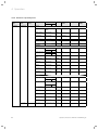
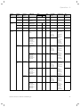
4.3.2
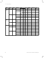
Overview of operating levels
Selection
level 1
Selection
level 2
Information
System status
Selection
level 3
Setting level
Values
min.
Unit
Increment/
Select
max.
Factory reset
Own
setting
System
Status
Current value (¬ Section 6)
–
Water pressure
Current value
bar
Domestic hot
water
Current value
–
Collector temp 1)
Solar yield 1)
Current value
Current value
°C
kWh
Reset solar yield 1)
HEATING 1
Current value
–
Yes, No
No
Day temperature
Current value
°C
0.5
20
Night temperature
Current value
5
30
Current value
°C
0.5
15
Auto day temp
until
Current value
h:min
away from
Current value
dd.mm.
yy
away to
Current value
dd.mm.
yy
At home from
Current value
dd.mm.
yy
At home to
Current value
dd.mm.
yy
Current value
°C
0.5
°C
0.5
5
Room temperature 3)
Charged,
Charging
30
°C
HEATING 2 2)
Day temperature
5
Night temperature
Current value
5
Solar yield 1)
Tab. 4.2
16
30
30
Auto day temp
until
Current value
h:min
away from
Current value
dd.mm.
yy
away to
Current value
dd.mm.
yy
At home from
Current value
dd.mm.
yy
At home to
Current value
dd.mm.
yy
Bar chart
Previous year to current year comparison
kWh/
month
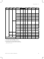
Overview of operating levels
Operating instructions VRC 470f 0020124644_00
Operation 4
Selection
level 1
Selection
level 2
Information
Contact details
Installer
Phone
Serialnummer
Number of the
appliance
Permanent value
HEATING 1
Day/
Night set-back
5
HEATING 2 2)
Day/
Night set-back
Domestic hot
water
HEATING 1
Desired temperatures
Time programmes
Selection
level 3
HEATING 2 2)
Domestic hot
water
Preparation
Circulation
Tab. 4.2
Setting level
Values
min.
max.
Current values
Unit
Increment/
Select
Factory reset
30
°C
0.5°C
20
15
5
30
°C
0.5°C
20
15
Domestic hot
water
35 4)
70 4)
°C
1°C
60 4)
Individual days
and
blocks
–
–
–
Time period 1:
Start - End
Time period 2:
Start - End
Time period 3:
Start - End
00:00
24:00
h:min
Mon, Tue, Wed,
Thu, Fri, Sat, Sun
and
Mon - Fri,
Sat - Sun,
Mon - Sun
10 min
Mon - Fri:
06:00-22:00
Sat:
07:30-23:30
Sun:
07:30-22:00
and
Mon - Fri
06:00-22:00
Sat-Sun
7:30-23:30
Mon-Sun
06:00-22:00
Individual days
and
blocks
–
–
–
Mon, Tue, Wed,
Thu, Fri, Sat, Sun
and
Mon - Fri,
Sat - Sun,
Mon - Sun
Time period 1:
Start - End
Time period 2:
Start - End
Time period 3:
Start - End
00:00
24:00
h:min
10 min
Mon - Fri:
06:00-22:00
Sat:
07:30-23:30
Sun:
07:30-22:00
and
Mon - Fri
06:00-22:00
Sat-Sun
7:30-23:30
Mon-Sun
06:00-22:00
Individual days and
blocks
–
–
–
Time period 1:
Start - End
Time period 2:
Start - End
Time period 3:
Start - End
00:00
24:00
h:min
Mon, Tue, Wed,
Thu, Fri, Sat, Sun
and
Mon - Fri,
Sat - Sun,
Mon - Sun
10 min
Individual days and
blocks
–
–
–
Time period 1:
Start - End
Time period 2:
Start - End
Time period 3:
Start - End
00:00
24:00
h:min
Mon, Tue, Wed,
Thu, Fri, Sat, Sun
and
Mon - Fri,
Sat - Sun,
Mon - Sun
10 min
Own
setting
Mon - Fri:
05:30-22:00
Sat:
07:00-23:30
Sun:
07:00-22:00
and
Mon - Fri
05:30-22:00
Sat-Sun
07:00-23:30
Mon-Sun
05:30-22:00
Mon - Fri:
06:00-22:00
Sat:
07:30-23:30
Sun:
07:30-22:00
and
Mon - Fri
06:00-22:00
Sat-Sun
7:30-23:30
Mon-Sun
06:00-22:00
Overview of operating levels
Operating instructions VRC 470f 0020124644_00
17
4 Operation
Selection
level 1
Selection
level 2
Days away
from home
scheduling
HEATING 1
Selection
level 3
Unit
Increment/
Select
Factory reset
dd.mm.
yy
Day.Month.Year
01.01.10
31.12.99
dd.mm.
yy
Day.Month.Year
01.01.10
30
°C
0.5°C
Frost protection
31.12.99
dd.mm.
yy
Day.Month.Year
01.01.10
01.01.00
31.12.99
dd.mm.
yy
Day.Month.Year
01.01.10
30
°C
0.5°C
Frost protection
Start
Frost protection
or 5
01.01.00
31.12.99
dd.mm.
yy
Day.Month.Year
01.01.10
End
01.01.00
31.12.99
dd.mm.
yy
Day.Month.Year
01.01.10
Start
01.01.00
31.12.99
dd.mm.
yy
Day.Month.Year
01.01.10
End
01.01.00
31.12.99
dd.mm.
yy
Day.Month.Year
01.01.10
Language
–
–
–
–
Languages for
selection
German
Date / Time
Time
00:00
24:00
h:min
10 min
00:00
Date
01.01.00
31.12.99
dd.mm.
yy
Day.Month.Year
01.01.00
–
Off, Auto
off
HEATING 2 2)
Days at home
scheduling
HEATING 1
HEATING 2 2)
Basic settings
Setting level
Start
Values
min.
01.01.00
max.
31.12.99
End
01.01.00
Temperature
Start
Frost protection
or 5
01.01.00
End
Temperature
Day-light savings
Display
Tab. 4.2
18
Display contrast
01
15
–
1
8
Offset room temp
-3.0
3.0
K
0.5
0.0
Offset
outside temp.
-3.0
3.0
K
0.5
0.0
Own
setting
Overview of operating levels
Operating instructions VRC 470f 0020124644_00
Operation 4
Selection
level 1
Selection
level 2
Selection
level 3
Setting level
Basic settings
Mode 2)
HEATING 1
HEATING 2
Change heating circuit
naming
Factory reset
Installer level
Tab. 4.2
1)
2)
3)
4)
Unit
Factory reset
max.
–
Increment/
Select
Automatic mode
active or
Summer mode or
Comfort mode or
Set-back mode or
System OFF
Cylinder boost
Values
min.
–
–
Active, Not
active
Automatic
mode active
–
–
–
Active, Not
active
Not active
Party function
–
–
–
Active, Not
active
Not active
1 day away from
home
–
–
–
Active, Not
active
Not active
1 day at home
–
–
–
Active, Not
active
Not active
Ventilation boost
–
–
–
Active, Not
active
Not active
Automatic mode
active or
Summer mode or
Comfort mode or
Set-back mode or
System OFF
Cylinder boost
–
–
–
Active, Not
active
Automatic
mode active
–
–
–
Active, Not
active
Not active
Party function
–
–
–
Active, Not
active
Not active
1 day away from
home
–
–
–
Active, Not
active
Not active
1 day at home
–
–
–
Active, Not
active
Not active
Ventilation boost
–
–
–
Active, Not
active
Not active
Heating 1
1
10
Letter/
number
A to Z,
0 to 9, space
Heating 1
Heating 2 2)
1
10
Letter/
number
A to Z,
0 to 9, space
Heating 2
Time programmes
–
–
–
Yes, No
No
Everything
–
–
–
Yes, No
No
Enter code
000
999
–
1
000
Own
setting
Overview of operating levels
Is only shown if solar module VR 68/2 is connected.
Is only shown if mixer module VR 61/2 is connected.
Is only shown if remote control unit VR 81/2 is connected.
This value depends on the expansion module connected. If no
expansion module is connected, the upper limit may be limited
by the value for the boiler.
Operating instructions VRC 470f 0020124644_00
19
5 Description of functions
5
Description of functions
The controller offers various functions, modes and
advanced functions for controlling the heating circuit
and hot water production.
– With the functions, you can read information, and set
desired temperatures, periods and basic settings.
– With the modes, you select whether or not the heating circuit, hot water production and circulation
should be operated in automatic or manual mode.
– With the advanced functions, you can change the
active mode for the heating circuit and hot water production in special situations quickly and with time
restrictions.
5.1
Functions
You can set the functions via the left function key
"Menu".
The path details given at the start of each function
description indicate how you reach this function in the
menu structure.
You can read and set heating circuit 1 and, if relevant,
heating circuit 2 independently of one another.
5.1.1
Reading information
Menu ¬ Information
Select the "Information" list entry in selection level 1 to
reach selection level 2 with the list entries "System status", "Solar yield", "Contact details" and "Serial
number".
Reading the system status
Menu ¬ Information ¬ System status
The "System status" option shows you a list of system
parameters and their current settings/levels: Status,
Water pressure, Domestic hot water and the current settings for "HEATING 1" and if applicable "HEATING 2".
There is also information under "System status":
– regarding the active period ("Auto day temp until"),
– regarding exceptions in the time programmes, which
you may have set using the "Days away from home"
and "Days at home" functions.
Only the desired temperatures for "Day temperature"
and "Night temperature" can be also set directly under
"System status". All other values are set in other places
in the menu structure, as described in the following sections.
i
20
i
"HEATING 2" is only shown under "System
status" if a mixer module VR 61/2 is connected. "HEATING 2" has the same read
options and settings as "HEATING 1".
Reading the list of status messages
Menu ¬ Information ¬ System status ¬ Status
If no service is required and no errors have occurred,
the value "OK" is shown next to "Status". If a service is
required or an error has occurred, the value "Fault" is
shown next to "Status". In this case the right function
key has the function "Display". If you press the right
function key "Display", the list of status messages is
shown in the display.
i
The "Collector temp", "Solar yield" and
"Reset solar yield" list entries are only shown
under "System status" if a solar module
VR 68/2 is connected.
Reset solar yield (only with VR 68/2)
Menu ¬ Information ¬ System status ¬ Reset solar
yield
If you select the setting "Yes" under function "Reset
solar yield" and press the right function key "Ok", you
reset the previously totalled solar yield to 0 kWh. After
30 seconds the setting "Yes" automatically returns to
"No".
Display solar statistics (only with VR 68/2)
Menu ¬ Information ¬ Solar yield
The diagram under "Solar yield" shows a comparison of
the monthly solar yields of the previous year and of the
current year as well as the peak values of the last
month.
Display installer contact details
Menu ¬ Information ¬ Contact details
If the heating engineer entered his company name and
telephone number during the installation, you can read
this data under "Contact details".
Reading the serial number and article number
Menu ¬ Information ¬ Serialnummer
"Serialnummer" shows the serial number of the appliance, which the heating engineer may require you to tell
him.
The article number is found in the second line of the
serial number (¬ Fig. 4.10).
The "Room temperature" list entry is only
shown under "System status" if a remote control unit VR 81/2 is connected.
Operating instructions VRC 470f 0020124644_00
Description of functions 5
5.1.2
Setting desired temperatures
Menu ¬ Desired temperatures
This function is used to set the desired temperatures for
the heating circuits "HEATING 1", "HEATING 2", if relevant, and hot water production.
i
"HEATING 2" is only shown under "Desired
temperatures" if a mixer module VR 61/2 is
connected. "HEATING 2" has the same read
options and settings as "HEATING 1".
For the heating circuits
Menu ¬ Desired temperatures ¬ HEATING 1 and, if
relevant, HEATING 2
b
Caution!
Risk of damage due to frost!
If rooms are not adequately heated, this can
cause damage to the building and to the heating system.
> If you are absent during a frosty spell,
ensure that the heating system remains in
operation and provides adequate frost protection.
You can set two different desired temperatures for the
heating circuits.
– The desired day temperature is the temperature you
wish to have in the rooms during the day or when you
are at home (Comfort mode).
– The desired night temperature is the temperature
that you wish to have in the rooms during the night
or when you are away from home (Night mode).
For hot water production
Menu ¬ Desired temperatures ¬ Domestic hot water
You can only use the controller's functions and setting
options for hot water production if a domestic hot water
cylinder is connected to the heating system.
a
Danger!
Risk of being scalded by hot water!
There is a danger of scalding at the hot water
draw-off points if the temperatures are
greater than 60 °C. Young children and elderly persons can be at risk at lower temperatures.
> Select the temperature so that nobody is
at risk.
You can set the desired "Hot water" temperature for the
domestic hot water.
Operating instructions VRC 470f 0020124644_00
21
5 Description of functions
Setting timer programmes
Desired
day
temperature
Desired
day
temperature
Desired
night
temperature
Temperature
5.1.3
21 °
Desired
night
temperature
Desired night temperature
Desired
day
temperature
Desired
night
temperature
Period 2
Period 1
06:00
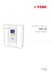
Fig. 5.1
08:00
16:30 18:00
20:00
22:30
Time
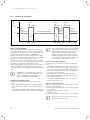
Example: three time periods in one day
Menu ¬ Time programmes
Select the "Time programmes" function to set the periods for the heating circuit and for hot water production.
If you have not set any periods, the controller uses the
periods set in the factory settings (¬ Tab. 4.2).
You can only use the controller's functions and setting
options for hot water production if a domestic hot water
cylinder is connected to the heating system.
You can only use the controller's functions and setting
options for circulation if circulation pipes and a circulation pump are connected to the heating system.
The time programmes are only effective for the heating
circuit in "Automatic mode" and are only effective for
hot water production in "Automatic mode" and "Summer
mode".
i
"HEATING 2" is only shown under "Time programmes" if a mixer module VR 61/2 is connected. "HEATING 2" has the same read
options and settings as "HEATING 1".
Periods for the heating circuit
Set the period for the heating circuit so that each
period:
– starts approx. 30 minutes before the time at which
the rooms should reach the desired "Day" temperature.
– ends approx. 30 minutes before the time at which the
rooms should reach the desired "Night" temperature.
i
The heating engineer can set a pre-heat time
and a pre-switch-off time for the heating circuit, so that you can set the period for the
desired "Day" and "Night" temperatures
exactly to the times at which the room temperature should reach the desired temperature. Ask the heating engineer if he has set a
pre-heat time or a pre-switch-off time.
Periods for hot water production
Set the periods for hot water production so that each
period:
– starts approx. 30 minutes before the time at which
the water in the domestic hot water cylinder should
have reached the desired "hot water" temperature.
– ends approx. 30 minutes before the time at which you
no longer need any hot water.
Set the periods for circulation so that each period:
– starts approx. 30 minutes after the start of a period
for hot water production,
– ends approx. 30 minutes before the end of a period
for hot water production.
Periods for days and blocks
You can set individual days or blocks of days for which
the periods should apply:
– Monday, Tuesday, Wednesday, Thursday, Friday, Saturday, Sunday
– Monday - Friday, Saturday - Sunday,
Monday - Sunday
For each day and block, you can set up to three periods.
i
22
Period 3
16 °
The periods set for a day have priority over
the periods set for a block.
Operating instructions VRC 470f 0020124644_00
Description of functions 5
Example: three time periods in one day (¬ Fig. 5.1)
Desired "Day" temperature: 21 °C
Desired "Night" temperature: 16 °C
Time period 1: 06.00 - 08.00
Time period 2: 16.30 - 18.00
Time period 3: 20.00 - 22.30
Within the periods, the controller brings the room temperature to the set desired "Day" temperature (Comfort
mode).
Outside the period, the controller brings the room temperature to the set desired "Night" temperature (Night
mode).
Examples of individual days:
Monday
Time period 1: 06.00 - 07.30
Examples of blocks:
Monday - Friday
Time period 1: 06.30 - 08.00
Time period 2: 12.00 - 13.00
Time period 3: 17.00 - 22.00
Saturday - Sunday
Time period 1: 08.00 - 22.00
Setting time programmes quickly:
If, for example, you need a different period for just one
working day in the week, first set the times for the
entire block "Monday - Friday". Then set the different
period for the working day.
If you view a block in the display and have defined a different period for a day in this block, then the display
indicates the different times in the block with "!!".
Back
Back
Fig. 5.3
Ok
Exception to the time programme message
The set times for the block marked with "!!" can be
viewed and changed if you press the right function key
"Ok" in the display.
For the heating circuits:
Menu ¬ Time programmes ¬ HEATING 1 and, if relevant, HEATING 2
In each set period, the desired temperature that you set
in the "Desired temperatures" function applies.
Within the period, the controller switches to Comfort
mode and the heating circuit heats the connected rooms
to the desired "Day" temperature.
Outside of that time period, the controller switches to
the operating mode that the heating engineer has set:
Frost protection, Eco, or Night-time temperature (¬ Section 5.2.1).
Saturday
Time period 1: 07.30 - 10.00
Time period 2: 12.00 - 23.30
Monday - Sunday
Period 1:
Period 2:
Period 3:
Individual days
vary from
Mo - Su block.
!! : !! - !! : !!
!! : !! - !! : !!
!! : !! - !! : !!
Select
Fig. 5.2 Identification of different days
If you press the right function key "Select", then a message appears on the display which informs you about
different periods. You do not need to align the times.
Operating instructions VRC 470f 0020124644_00
For hot water production:
Menu ¬ Time programmes ¬ Domestic hot water
¬ Preparation
In each set period, the desired hot water temperature
that you set in the "Desired temperatures" function
applies.
Within the period, the hot water is available at the temperature set by you. If, during the period, the cylinder
temperature is 5 °C lower than the desired hot water
temperature, the domestic hot water cylinder is again
heated to the desired hot water temperature. At the end
of a period, the controller switches the hot water production off, until the start of the next period.
For circulation:
Menu ¬ Time programmes ¬ Domestic hot water
¬ Circulation
The set periods determine the operating times for circulation. Within the period, circulation is activated. Outside
the period, circulation is deactivated.
Coordinate the periods for circulation with the periods
for hot water production. If, for example, the period for
hot water production starts at 05:00, then the period
for circulation should start 30 minutes later at 05:30.
23
5 Description of functions
5.1.4
Days away from home scheduling
Menu ¬ Days away from home scheduling ¬ HEATING 1 and, if relevant, HEATING 2
With this function, you can set a period with a start and
end date and a temperature for days during which you
are away from home. Thus, you do not need to change
periods for which you have set, for example, no reduction of the desired temperature over the course of the
day.
Hot water production and circulation are switched off
and the frost protection is activated.
While the "Days away from home scheduling" function is
activated it has priority over the set operating mode. At
the end of the specified period, or if you cancel the function, the heating system returns to the pre-set mode.
i
5.1.5
Menu ¬ Days at home scheduling ¬ HEATING 1 and, if
relevant, HEATING 2
With this function, you set the desired "Day" temperature for days which you spend at home. This means you
do not need to change the periods which you have
already set, for example, with a decrease in the desired
temperature during the day.
Within the specified period, the heating system works in
"Automatic mode" and uses the day settings for "Sunday", which were set using the "Time programmes"
function.
At the end of the specified period, or if you cancel the
function, the heating system returns to the pre-set
mode.
"HEATING 2" is only shown under "Day at
home scheduling" if a mixer module VR 61/2 is
connected. "HEATING 2" has the same read
options and settings as "HEATING 1".
Language selection
Menu ¬ Basic settings ¬ Language
i
During installation, the heating engineer sets
the desired language. All functions are displayed in the set language.
If the language of e.g. a service technician differs from
the set language, you can change the language using
this function.
b
"HEATING 2" is only shown under "Days away
from home scheduling" if a mixer module
VR 61/2 is connected. "HEATING 2" has the
same read options and settings as "HEATING 1".
Days at home scheduling
i
5.1.6
Caution!
It may not be possible to operate the controller if the wrong language is selected.
If you select a language that you do not
understand, you can no longer read the text
in the controller display and can no longer
operate the controller.
> Only select a language that you understand.
However, if the text in the display should appear in a language that you do not understand, you can set a different language as follows:
> Repeatedly press the left function key until the basic
display appears.
> Press the left function key once again.
> Turn the control knob to the left until the second list
entry above the dotted line is highlighted.
> Press the right function key twice.
> Turn the control knob (to the right or left) until you
find a language you understand.
> Press the right function key.
5.1.7
Setting the time
Menu ¬ Basic settings ¬ Date / Time ¬ Time
Select this function to set the current time.
All controller functions that contain a time relate to the
set time.
5.1.8
Setting the date
Menu ¬ Basic settings ¬ Date / Time ¬ Date
Select this function to set the current date.
All controller functions that contain a date relate to the
set date.
24
Operating instructions VRC 470f 0020124644_00
Description of functions 5
5.1.9
Changing over to daylight saving time
Menu ¬ Basic settings ¬ Date / Time ¬ Day-light savings
If the external sensor is not fitted with a DCF77 receiver
or if no DCF77 signal can be received, you can use this
function to set manual switchover to daylight savings
time.
– "Auto": the controller changes over to "Day-light savings" automatically.
– "Off": you have to change over to "Day-light savings"
manually.
i
5.1.10
Daylight saving is also referred to as BST
(British Summer Time): start = last Sunday in
March, end =- last Sunday in October.
Setting the display contrast
Menu ¬ Basic settings ¬ Display ¬ Display contrast
You can set the display contrast in relation to the brightness of the surroundings, to ensure that the display is
clearly legible.
5.1.11
Setting the offset room temperature
Menu ¬ Basic settings ¬ Display ¬ Offset room temp
A thermometer is integrated in the controller for measuring the room temperature. If you have another thermometer in the same room and compare the values with
each other, the temperature values may constantly differ
from each other.
Example:
One room thermometer constantly shows a temperature
that is one degree higher than the current room temperature on the controller display.
With the "Offset room temp." function, you can offset
the temperature difference in the controller display by
setting a correction value of +1 K (1 K corresponds to
1 °C). K (Kelvin) is a unit for the temperature difference.
Inputting a correction value affects the room temperature compensator.
5.1.12
Setting the offset outside temperature
Menu ¬ Basic settings ¬ Display ¬ Offset outside
temp.
The thermometer in the controller's external sensor
measures the outside temperature. If you have mounted
another thermometer in the outside area and compare
the temperature values with each other, the temperature
values may constantly differ from each other.
Example:
Your weather station constantly shows a temperature
that is one degree higher than the current room temperature on the controller display.
With the "Offset outside temp." function, you can offset
the temperature difference in the controller display by
setting a correction value of -1 K (1 K corresponds to 1 °C).
K (Kelvin) is a unit for the temperature difference.
Inputting a correction value affects the weather compensator.
5.1.13
Changing heating circuit naming
Menu ¬ Basic settings ¬ Change heating circuit naming
You can change the factory-set names for the heating
circuits "HEATING 1" and, if relevant "HEATING 2" as you
wish. The name is limited to 10 characters.
5.1.14
Restoring factory settings
Menu ¬ Basic settings ¬ Factory reset
You can reset the settings for the "Time programmes"
or for "Everything" to the factory settings.
Time programmes
Menu ¬ Basic settings ¬ Factory reset ¬ Time Programmes
i
Before you reset the time programmes to the
factory settings, make a note of the controller
settings (¬ Tab. 4.2).
With "Time programmes", you will reset all the settings
you have made in the "Time programmes" function to
the factory settings. All other settings that include
times, such as "Date / Time", are not affected.
While the controller is resetting the "Time programmes"
settings to the factory settings, "in process" is shown on
the display. Then the basic display is displayed.
Operating instructions VRC 470f 0020124644_00
25
5 Description of functions
Everything
Menu ¬ Basic settings¬ Factory reset ¬ Everything
b
Caution!
Risk of a malfunction!
The function "Everything" restores all settings
to the factory settings, including those set by
the heating engineer. It may be that it is no
longer possible to operate the heating system
after this.
> Arrange for the heating engineer to reset
all settings to factory settings.
While the controller is resetting the settings to the factory settings, "in process" is shown on the display. Then
the installation assistant appears in the display, which
only the heating engineer may operate.
5.1.15
Installer level
Installer level is reserved for the heating engineer and is
therefore protected by an access code.
At this operating level the heating engineer can make
the necessary settings.
5.2
Operating modes
You can set the modes using the right function key
"Mode" and, if relevant, also by means of the left function key "Menu" under "Basic settings".
i
The "Mode" list entry is only shown under
"Basic settings" and, further down, also the
"HEATING 1" and "HEATING 2" list entries, if a
mixer module VR 61/2 is connected.
Use the right function key "Mode" to set the mode
directly. The set mode only applies to the heating circuit
that has been pre-set by the heating engineer ("HEATING 1" or "HEATING 2" or "HEATING 1 and HEATING 2").
Only if a mixer module VR 61/2 is connected for a second heating circuit and both heating circuits are activated can you also set the mode via the left function key
"Menu". You can then set the modes for "HEATING 1"
and "HEATING 2" separately.
The path details given at the start of each mode description indicate how you reach this mode in the menu
structure.
26
5.2.1
Operating modes for the heating circuit
Automatic mode
Mode ¬ (current operating mode) ¬ Automatic mode
or where applicable
Menu ¬ Basic settings ¬ Mode ¬ HEATING 1 and, if
relevant, HEATING 2 ¬ (current mode) ¬ Automatic
mode
Automatic mode controls the heating circuits according
to the set desired "Day" temperature, the set periods,
the desired "Night" temperature set by the heating engineer and the heating curve.
In the "Time programmes" function, you have set periods for the heating circuits. If you have not set any periods, the controller uses the periods set in the factory
settings in automatic mode (¬ Tab. 4.2).
Within the periods, the controller brings the room temperature to the set desired "Day" temperature (Comfort
mode).
Outside the periods, the controller regulates in accordance with the mode set by the heating engineer.
Three modes are possible:
– ECO (factory setting): the heating function is
switched off and the controller monitors the outside
temperature.
If the outside temperature falls below 3 °C, the controller switches the heating function on after the end
of the frost protection delay time and brings the room
temperature to the set desired "Night" temperature.
Even though the heating function is on, the burner is
only active as required.
If the outside temperature rises above 4 °C, the controller switches the heating function off, but continues to monitor the outside temperature.
– Frost protection: the heating function is switched off
and the frost protection function is active.
– Night temperature: the heating function is on and
the controller controls the room temperature according to the set "Night" temperature.
When installing your controller, the heating engineer can
specify the control functions for the times outside the
periods and the heating curve.
> Discuss with the heating engineer which settings are
optimum for you.
Summer mode
Mode ¬ (current mode) ¬ Summer mode
or where applicable
Menu ¬ Basic settings ¬ Mode ¬ HEATING 1 and, if
relevant, HEATING 2 ¬ (current mode)
The heating function is switched off for the selected
heating circuit and the frost protection function is
active. Hot water production and circulation are regulated by the controller in accordance with the periods
set.
Operating instructions VRC 470f 0020124644_00
Description of functions 5
Comfort mode
Mode ¬ (current operating mode) ¬ Comfort mode
or where applicable
Menu ¬ Basic settings ¬ Mode ¬ HEATING 1 and, if
relevant, HEATING 2 ¬ (current mode) ¬ Comfort
mode
The "Comfort mode" controls "HEATING 1" and, if relevant, "HEATING 2" at the set desired "Day" temperatures without taking periods into account.
Within the period, hot water production is switched on
and keeps the hot water in the domestic hot water cylinder at the set temperature. Outside the period, hot
water production is deactivated.
Automatic mode and Summer mode control the circulation of hot water in the hot water pipes in accordance
with the set periods.
Within the periods, circulation is activated and outside
the periods it is deactivated.
Set-back mode
Mode ¬ (current mode) ¬ Set-back mode
or where applicable
Menu ¬ Basic settings ¬ Mode ¬ HEATING 1 and, if
relevant, HEATING 2 ¬ (current mode) ¬ Set-back
mode
The "Set-back mode" controls "HEATING 1" and, if relevant, "HEATING 2" at the set desired "Night" temperatures without taking periods into account.
Comfort mode
Comfort mode controls hot water production in accordance with the set desired temperature for hot water
without taking periods into account.
Circulation is activated and the periods for circulation
are not observed.
System OFF
Mode ¬ (current mode) ¬ System OFF
The heating function is switched off. The frost protection
function is activated.
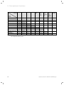
5.2.2
Operating modes for hot water production and
circulation
i
The mode for hot water production and circulation depends on the set mode for heating
circuits "HEATING 1" and, if relevant, "HEATING 2". No other mode can be set.
i
If you have assigned different functions,
modes or advanced functions to two independent heating circuits, then the controller
assigns the mode with the greater heat
requirement to hot water production and circulation (¬ Tab. 5.1).
Set-back mode and System OFF
Hot water production and circulation are off. The frost
protection function is activated.
With two independent heating circuits:
If the heating system has two independent heating circuits, the controller always assigns the mode with the
greater heat requirement to hot water production and
circulation. To find out which mode this is, see the table
(¬ Tab. 5.1).
Example:
If you operate Circuit 1 in "Auto" mode and Circuit 2 in
"Comfort" mode, the controller assigns "Comfort" mode
to hot water production and circulation.
If the heating system is equipped with one heating circuit, the controller regulates the hot water production
and, if relevant, the circulation in accordance with the
mode for this heating circuit.
If the heating system is equipped with two heating circuits, the heating engineer can define which heating circuit controls the hot water production and, if relevant,
the circulation.
Automatic mode and Summer mode
Automatic mode and Summer mode control the hot
water production in accordance with the set desired
temperature for "hot water" and the set periods. In the
"Time programmes" function, you have set periods for
hot water production. If you have not set any periods,
the controller uses the period set in the factory settings
for hot water production (¬ Tab. 4.2).
Operating instructions VRC 470f 0020124644_00
27
5 Description of functions
Heating Auto
circuit 2
Comfort
Set-back
Summer
1 day at
home
1 day
away
from
home
Days at
home
scheduling
Days
away
from
home
scheduling
Party
function
Auto
Auto
Comfort
Auto
Auto
Auto
Auto
Auto
Auto
Comfort
Comfort
Comfort
Comfort
Comfort
Comfort
Comfort
Comfort
Comfort
Comfort
Comfort
Set-back
Auto
Comfort
Off
Auto
Auto
Off
Auto
Off
Comfort
Summer
Auto
Comfort
Auto
Auto
Auto
Auto
Auto
Auto
Comfort
1 day at home
Auto
Comfort
Auto
Auto
Auto
Auto
Auto
Auto
Comfort
1 day away from home
Auto
Comfort
Off
Auto
Auto
Off
Auto
Off
Comfort
Days at home scheduling
Auto
Comfort
Auto
Auto
Auto
Auto
Auto
Auto
Comfort
Days away from home
scheduling
Auto
Comfort
Off
Auto
Auto
Off
Auto
Off
Comfort
Party function
Comfort
Comfort
Comfort
Comfort
Comfort
Comfort
Comfort
Comfort
Comfort
Heating
circuit 1
Tab. 5.1
28
Modes for hot water production and circulation with
two independent heating circuits
Operating instructions VRC 470f 0020124644_00
Description of functions 5
5.3
Advanced functions
Advanced functions can be activated directly from any
mode using the right function key "Mode". In this case,
the activated advanced function only applies to the
heating circuit that has been pre-set by the heating
engineer ("HEATING 1" or "HEATING 2" or "HEATING 1
and HEATING 2").
Only if a mixer module VR 61/2 is connected for a second heating circuit and both heating circuits are activated can you also activate an advanced function via the
left function key "Menu".
In this case, you can set the advanced function separately for each heating circuit.
You can cancel an advanced function at any time using
the left function key "Cancel".
5.3.2
Party function
Mode ¬ Party function
or where applicable
Menu ¬ Basic settings ¬ Mode ¬ HEATING 1 and, if
relevant, HEATING 2 ¬ Party function
Party function active
°C
21,5
Desired temperature 22,0°C
Cancel
Fig. 5.4 Example: Party function activated
The path details given at the start of each advanced
function description indicate how you reach this
advanced function in the menu structure.
5.3.1
Cylinder boost
Operating mode ¬ Cylinder boost
If you have switched off hot water production or
required hot water outside a period, then activate the
"Cylinder boost" advanced function.
The advanced function heats the water in the domestic
hot water cylinder once, until the set desired "hot water"
temperature is reached or until you cancel the advanced
function.
The heating system will then return to the pre-set mode.
Operating instructions VRC 470f 0020124644_00
If you wish to switch on the heating circuit, the hot
water production and circulation temporarily, e.g. during
a party, activate the "Party function" advanced function.
This means you do not need to change the settings on
the heating system for short periods of time.
The advanced function brings the room temperature to
the set desired "Day" temperature, in accordance with
the set periods.
If the display shows "Party function active", you can set
the desired temperature (Day) for the heating circuit
with the control knob. The setting applies for as long as
the advanced function is active.
The advanced function is deactivated when the next
period starts or if you cancel the advanced function first.
The heating system will then return to the pre-set mode.
29
5 Description of functions
5.3.3
1 Day away from home
Mode ¬ 1 Day away from home
or where applicable
Menu ¬ Basic settings ¬ Mode ¬ HEATING 1 and, if
relevant, HEATING 2 ¬ 1 Day away from home
If you are only away from home for one day, e.g. for a
day trip, activate the "1 Day away from home" advanced
function. This means you do not need to change the set
periods, which you have set with, e.g., an increase in the
room temperature during the day.
The advanced function brings the room temperature to
the desired "Night" temperature. Hot water production
and circulation are switched off and the frost protection
is activated.
If the display shows "1 Day away from home active", you
can set the desired temperature (Night) for the heating
circuit with the control knob.
The advanced function is automatically deactivated after
24:00 hours or if you cancel the advanced function first.
The heating system will then return to the pre-set mode.
5.3.4
5.3.5
Ventilation boost
Mode ¬ Ventilation boost
or where applicable
Menu ¬ Basic settings ¬ Mode ¬ HEATING 1 and, if
relevant, HEATING 2 ¬ Ventilation boost
If you wish to switch the heating circuit off during ventilation of the living rooms, activate the "Ventilation
boost" advanced function. This advanced function
switches the heating circuit off for 30 minutes. The frost
protection function is activated, and hot water production and circulation remain active.
The advanced function is automatically deactivated after
30 minutes or if you cancel the advanced function first.
The heating system will then return to the pre-set mode.
1 day at home
Mode ¬ 1 day at home
or where applicable
Menu ¬ Basic settings ¬ Mode ¬ HEATING 1 and, if
relevant, HEATING 2 ¬ 1 day at home
If you are spending a week day at home, e.g on a public
holiday, then activate the "1 day at home" advanced
function. The advanced function activates "Automatic
mode" for one day with the settings for "Sunday", as set
using the "Time programmes" function.
If the display shows "1 day at home active", you can set
the desired temperature (Day) for the heating circuit
with the control knob.
The advanced function is automatically deactivated after
24:00 hours or if you cancel the advanced function first.
The heating system will then return to the pre-set mode.
30
Operating instructions VRC 470f 0020124644_00
Service and troubleshooting 6
6
Service and troubleshooting
6.3
Detecting and rectifying faults
If a fault occurs in the heating system, the controller displays an error message in the display.
6.1
Service
If a service is required, the controller displays a service
message in the display.
b
Caution!
Risk of damage to the heating system due
to failure to perform maintenance work!
A service message indicates that the heating
system must be serviced by the heating engineer. Failure to take notice of these service
messages, could lead to material damage or
breakdown of the heating system.
> If the controller displays a service message,
inform a heating engineer.
Service heat generator
19°C
Desired temperature 21°C
Menu
Fig. 6.1
!
Heat generator fault
Mode
Example of a service message
The heating engineer can set a period in the controller
for the next service interval for the heating system or
boiler. At the end of the service interval the service
warning will appear on the fist line of the basic display.
The following service messages may appear:
– "Service heat generator"
– "Service" (of the heating system).
6.2
b
Caution!
Risk of damage to the heating system due
to failure to perform troubleshooting work!
An error message indicates that the heating
engineer must perform troubleshooting or
repair work on the heating system. Failure to
take notice of these error messages could
lead to material damage or breakdown of the
heating system.
> If the controller displays the error message
"Clean outside temperature sensor/transmitter" or "Replace battery", proceed as
described in (¬ Section 6.3.2) or (¬ Section 6.3.3).
> If the controller displays any other error
message, inform a heating engineer.
Cleaning the controller
> Clean the casing of the controller with a damp cloth.
> Never use scouring or cleaning agents which could
damage the operating elements or the display.
Operating instructions VRC 470f 0020124644_00
Back
Fig. 6.2 Example of an error message
If the controller shows an error message in the display
instead of the basic display and you press the left function key "Back", then the basic display appears again.
You can also read current error messages under "Menu
¬ Information ¬ System status ¬ Status". As soon as an
error message for the heating system appears, the "Status" setting will show "Fault". In this case the right function key has the function "Display".
> Press the right function key "Display" to display the
list of error messages.
31
6 Service and troubleshooting
6.3.1
Display remains dark
i
The controller is battery-powered. To save
power and so extend the life of the batteries,
the display is normally switched off. If you
press one of the function buttons or the control knob, the backlighting switches on and
the basic display appears. The backlighting
goes out approx. 10 seconds after the last
operation. The display switches off approx.
1 minute after the last operation.
6.3.2
a)
Error message "Clean outside temperature
sensor/transmitter"
The battery voltage on the outside temperature
sensor transmitter is too low because the solar cell
is dirty.
1
The display remains dark even though you have pressed
one of the function buttons or turned the control knob.
> Replace all the batteries in the controller (¬ Section 6.3.3).
If, after you have fitted new batteries, the screen still
remains dark or you are still unable to make any
changes using the function keys or control knob, then
there is a appliance fault for which the controller has
been unable to display an error message.
> Inform a heating engineer.
2
Fig. 6.3 Cleaning outside temperature sensor/transmitter
> Clean the solar cell (2) on the outside temperature
sensor/transmitter (1) using a damp cloth, or call your
heating engineer.
i
After you have cleaned the solar cell, there is
a delay before the error message disappears
because the battery first has to be recharged.
b)
If the error message continues to be displayed
after you have cleaned the solar cell and allowed
time for the battery to recharge, radio communication with the outside temperature sensor/transmitter has been lost.
> Inform a heating engineer.
i
32
If the outside temperature sensor fails, a fallback control mode is activated. An outside
temperature of 0 °C is then assumed. That
ensures basic operation of the heating system
until the fault has been rectified by the heating engineer.
Operating instructions VRC 470f 0020124644_00
Service and troubleshooting 6
6.3.3
Error message "Replace battery"
The controller batteries are almost discharged.
> Replace all the batteries in the controller.
Fig. 6.6 Layout and polarity of batteries
1
> Insert four new batteries of the same type in the controller.
i
2
Make sure battery poles are the right way
round (¬ Fig. 6.6).
Always replace all the batteries at the same
time.
Use only batteries of the type Alkaline AA/
LR6 Battery 1.5 V.
Do not use rechargeable batteries.
Depending on usage, the batteries should last
approx. 1 to 1.5 years.
> Close the battery compartment.
> Hook the controller back onto the wall-mounting base.
> Press the controller down onto the wall-mounting
base until it audibly clicks into position.
> Dispose of the old batteries correctly.
Fig. 6.4 Removing the VRC 470f
1 VRC 470f controller
2 Wall-mounting base
Proceed as follows:
> Pull the controller (1) upwards and off the wall-mounting base (2).
1
Fig. 6.5 Opening the battery compartment
To open the battery compartment on the underneath of
the controller:
> Lift the cover by releasing the catch (1) at the side.
> Remove the cover.
Operating instructions VRC 470f 0020124644_00
33
7 Energy-saving tips
7
Energy-saving tips
Desired "Day" temperature
Set the desired "Day" temperature only as high as would
be necessary for your comfort level. Each extra degree
Celsius would mean an increased energy consumption of
about 6 %.
Adjust the room temperature according to the purpose
of use of the room, using the thermostatic radiator
valve. For example, it is not necessary to heat bedrooms
or seldom used rooms to 20 °C.
Desired "Night" temperature
If you do not need a high room temperature, e.g. during
the night or if you are away from home, then reduce the
room temperature. To do this, set the desired "Night"
temperature in the "Desired temperature" function.
Set the desired "Night" temperature approx. 6 °C lower
than the desired "Day" temperature. A temperature of
more than 6 °C lower does not bring any further energy
saving, because then a greater amount of energy would
be required the next time the system had to heat up to
the desired "Day" temperature.
In addition, use the "Time programmes" function to
define times during which you do not need a high room
temperature. The periods for heating are active in "Automatic mode".
If you are absent for longer periods of time, e.g. on holiday, then it is worth lowering the temperature even further. To do this, set the temperature using the "Days
away from home scheduling" function.
Uniform heating
Often, in a dwelling with central heating, only one room
is heated. Through the surrounding surfaces of this
room, i.e. walls, doors, windows, roofs, floors, the
unheated adjoining rooms are also heated in an unregulated manner, i.e. unwanted heat energy is lost. The
capacity of the radiator of this one heated room is obviously not enough for such an operating mode. The result
is that the room can no longer be heated adequately
and there is an uncomfortable feeling of cold. The same
effect arises when doors between heated and unheated
/ barely heated rooms are left open.
False economy: the heating is running but despite that,
the room temperature is not comfortably warm.
If you heat all rooms evenly and according to their use,
then you will achieve a comfortable room climate and
energy-saving operation.
34
Thermostatic radiator valves and room temperaturecompensated controller
Thermostatic radiator valves on the radiators maintain
the room temperature exactly once set.
Exception: the thermostatic valves on the radiators in
the room in which the controller is fitted must be turned
fully on. The radiators are then controlled by the controller and thus maintain the set room temperature.
You can adjust the room temperature to suit your individual requirements and ensure economical operation of
your heating system using the thermostatic radiator
valves in combination with a room temperature-compensated controller.
Do not obstruct the controller
The controller must be able to record the circulating
room air unhindered. Do not obstruct the controller with
furniture, curtains or other objects.
Economic hot water production
Set the "Domestic hot water" desired temperature of
your domestic hot water cylinder only to the temperature you actually need, and under no circumstances
higher than 60 °C.
You should also use the "Time programmes" function for
hot water production in "Automatic mode" or "Summer
mode". Set the period so that the water is brought to
the desired "hot water" temperature shortly before it is
needed, e.g. in the morning after getting up and in the
evening after you return home.
If you do not need any hot water for a longer period of
time, switch hot water production off.
If you need hot water rarely or outside the set periods,
use the function "Cylinder boost".
Use the "Time programmes" function for circulation to
save energy. This will ensure that you have hot water
available immediately from the tap when you need it.
During other times, when the circulation pump is
switched off, you wil need to let the water run for
slightly longer before hot water comes out of the tap.
Ventilate correctly
A ventilation boost with fully opened windows and,
where possible, with a draught is essential for the room
climate and room temperature. The room air will be
replaced by outside air in 5 to 10 minutes during a ventilation boost. The air humidity falls and the room is easier to heat up. You will feel warmed even if the room
temperature is the same.
Use the advanced "Ventilation boost" function to control
the heating system in an energy-saving manner during
the ventilation boost.
Operating instructions VRC 470f 0020124644_00
Warranty and customer service 8
8
8.1
Warranty and customer service
Vaillant warranty
We only grant a Vaillant manufacturers warranty if a
suitably qualified engineer has installed the system in
accordance with Vaillant instructions. The system owner
will be granted a warranty in accordance with theVaillant
terms and conditions. All requests for work during the
guarantee period must be made to Vaillant Service Solutions (0870 6060 777).
8.2
Vaillant Service
To ensure regular servicing, it is strongly recommended
that arrangements are made for a Maintenance Agreement. Please contact Vaillant Service Solutions(0870
6060 777) for further details.
Operating instructions VRC 470f 0020124644_00
35
9 Decommissioning
9
9.1
Decommissioning
Replacing the controller
To replace the controller in the heating system with a
new one, the heating system needs to be shut down.
> These works should be carried out by a heating engineer.
9.2
Recycling and disposal
The controller and the associated transport packaging
consists largely of recyclable materials.
Appliance
Neither the controller or any of its accessories belong in
the household waste.
> Ensure that old appliances and any existing accessories are disposed of properly.
Packaging
Leave the disposal of the transport packaging to the
approved qualified servicing company that installed the
appliance.
Batteries
Used batteries should not be disposed of in the normal
household waste.
> When disposing of the batteries, make sure you follow
the applicable regulations.
36
Operating instructions VRC 470f 0020124644_00
Technical data 10
10 Technical data
i
Description
Unit
VRC 470f
Power supply voltage Umax
V
4 x 1.5 V (AA)
Battery life (alkaline)
Years
Approx. 1.5
Protection type
-
IP 20
Protection class
-
Maximum permissible
ambient temperature
The range of radio transmission inside buildings is heavily dependent on the local conditions (e.g. the design and structure of the
building). Consequently, an indoor range of
25 m cannot always be guaranteed. Outside of
enclosed spaces (outdoors) the range is more
than 100 m.
Description
Unit
Outside temperature sensor/transmitter VR 21
III
Power supply
-
From solar cell with
energy store
°C
50
Reserve power supply
(with full energy store)
Days
Approx. 20
Transmission frequency
MHz
868
Protection type
-
IP 44
Transmission power
mW
< 10
Protection class
-
III
Permissible operating temperature
°C
- 35 … + 60
Transmission frequency
MHz
868
Transmission power
mW
< 10
Outdoors
m
> 100
Inside building
m
Approx. 25
Range:
Outdoors
m
> 100
Inside building
m
Approx. 25
Height
mm
115
Width
mm
147
Depth
mm
50
Tab. 10.1 Technical data of VRC 470f radio controller
Description
Unit
Radio receiver
unit
Power supply voltage Umax
V
24
Current consumption
mA
< 60
Protection type
-
IP 20
Protection class
-
III
Maximum permissible
ambient temperature
°C
50
Transmission frequency
MHz
868
Transmission power
mW
< 10
Outdoors
m
> 100
Inside building
m
Approx. 25
Height
mm
115
Width
mm
147
Depth
mm
50
Range:
Height
mm
110
Width
mm
76
Depth
mm
41
Tab. 10.3 Technical data of VR 21 outside temperature sensor/
transmitter
Range:
Tab. 10.2 Technical data of radio receiver unit
Operating instructions VRC 470f 0020124644_00
37
11 Glossary
11
Glossary
Circulation
A circulation pump heats water in the circuit through
the hot water pipes. This means the hot water pipes do
not cool so rapidly. If you open a tap, hot water comes
out of the tap immediately. You can set a period for circulation in order to save energy.
DCF77 receiver
A DCF77 receiver receives a time signal. The time signal
sets the time and date automatically. The time and date
provide automatic switching between daylight savings
time and standard time.
Error message
An error message shows you that the heating system
has notified a fault to the controller.
Flow temperature
The boiler heats water which is pumped through the
heating installation. The temperature of this hot water
as it leaves the boiler is referred to as the flow temperature.
Frost protection delay time
By setting a frost protection delay time (installer level),
the activation of the heating control by the frost protection function (outside temperature < 3 °C) is delayed for
a specified time (1 to 12 hrs.). The set frost protection
delay time also works in the "ECO" setting. The frost
protection delay time starts when the outside temperature drops below 3 °C.
Heating circuit
A heating circuit is a closed circulation system of pipes
and heating devices (e. g. radiators). The heated water
from the boiler flows into the heating circuit and returns
to the boiler as cooled water.
A heating installation usually has at least one heating
circuit. However additional heating circuits can be connected, e.g. to supply several dwellings or additional
underfloor heating.
Heating curve
A heating curve shows the relationship between the outside temperature and the flow temperature. By selecting
a steeper or shallower heating curve, the heating engineer can influence the flow temperature and thus also
the room temperature as a function of the outside temperature.
Heating installation
The heating installation heats up the dwelling and produces hot water.
Legionella
Legionella are water-borne bacteria which can quickly
propagate and cause serious lung diseases. Legionella
occur wherever heated water provides the optimum conditions for multiplication. Temporarily heating the water
to above 60 °C kills off the legionella.
Operating level for the heating engineer
This operating level contains all the additional functions
that can be changed by the heating engineer; these
should not be changed without specialist knowledge.
This level is reserved for the heating engineer and is
therefore protected by an access code.
Operating level for the operator
This operating level contains all the functions available
to be changed by the operator.
Period
A period is a pre-set, defined period of time during
which the boiler, hot water production or the circulation
pump is on.
Pre-heat time
If the heating engineer has set a pre-heat time, then the
controller starts the heating circuit already during the
set pre-heat time before the first period of the day, so
that the desired "Day" temperature is reached already
at the start of the first period.
Preparation
The water in the domestic hot water cylinder is heated
by the boiler to the selected desired "hot water" temperature. If the temperature in the domestic hot water cylinder falls by specific amount, the water is heated up
again to the target "hot water" temperature.
Pre-switch-off time
If the heating engineer has set a pre-switch-off time,
then the heating system is not unnecessarily heated to
the desired "Day" temperature during the set preswitch-off time before the end of a period.
Protection class
Protection class denotes the classification and identification of electrical equipment with reference to the existing safety measures to prevent electric shocks.
Protection type
The level of protection indicates the suitability of electrical equipment for various ambient conditions and additionally the protection of people from potential hazards
during their use.
38
Operating instructions VRC 470f 0020124644_00
Glossary 11
Room temperature
The room temperature is the temperature actually
measured in the dwelling.
Selection level
Via a selection level, you access the next level of the
menu structure or settings that you can change.
Set-back temperature
The set-back temperature is the desired "Night" temperature, to which the controller lowers the room temperature outside the set period (Night mode).
Solar yield
The heat energy obtained by a solar system in a defined
period (usually one year). This heat energy is used to
heat up the domestic hot water cylinder.
With time programmes, you can also control the hot
water production and circulation in such a way that hot
water is available in the set periods with the set desired
"hot water" temperature.
Weather compensation
Automatic change to the hot water temperature depending on the outside temperature.
The outside temperature is measured by a separate sensor which is mounted in the open air, and the results are
transmitted to the controller. At low outside temperatures the controller provides an increased flow temperature; at higher outside temperatures the flow temperature is reduced.
Status message
A status message appears when you have activated an
advanced function. It remains visible for as long as the
advanced function is active.
Target hot water temperature
The target hot water temperature is the desired "hot
water" temperature to which you wish to water in the
domestic hot water cylinder.
Target room temperature
The target room temperature is the desired "Day" temperature to which you wish to heat the dwelling (Comfort mode).
Thermostatic radiator valve
Thermostatic radiator valves are mounted on radiators
and control the room temperature to the set value. If the
room temperature rises above the pre-set value, the
thermostatic radiator valve reduces the heating water
flow rate. If the room temperature falls below the pre-set
value, the thermostatic radiator valve opens and the
heating water flow rate increases and the room temperature rises again.
Timer programme
If you operate the heating system in "Auto" mode, then
you activate periods during which the controller
switches the heating system on and heats the connected
rooms to the set desired "Day" temperature (Comfort
mode). Outside these periods, the controller switches
the heating system to night mode and allows the heated
rooms to cool down to the set desired "Night" temperature (Night mode). When the desired "Night" temperature is reached, the controller maintains the room temperature prevents the heated rooms from cooling further until the start of the next period.
Operating instructions VRC 470f 0020124644_00
39
Index
Index
A
H
Advanced functions ...................................................... 20, 29
Anti-Legionella function ....................................................... 4
Article number ......................................................................... 3
article numbers ........................................................................ 3
Automatic mode
ECO ...................................................................................... 26
Frost protection................................................................ 26
Set-back temperature ..................................................... 26
HEATING 1 .................................................................................. 7
HEATING 2 ................................................................................. 7
Heating circuit comfort mode ........................................... 26
Heating circuits ........................................................................ 7
Heating circuit summer mode ........................................... 26
Heating circuit system off ................................................... 27
Hot water production automatic mode ............................ 27
Hot water production comfort mode ................................ 27
Hot water production summer mode ............................... 27
Hot water production system off ....................................... 27
C
Changing over to daylight saving time ........................... 25
Circulation ................................................................................. 7
Cleaning outside temperature sensor/transmitter....... 32
Comfort mode ........................................................................ 21
Control knob ............................................................................. 6
Customer service .................................................................. 35
Cylinder boost ....................................................................... 29
I
Identification plate .................................................................. 3
Installer level.......................................................................... 26
Intended use ............................................................................ 4
L
D
Day at home ........................................................................... 30
Day away from home ........................................................... 30
Days at home scheduling.................................................... 24
Days away from home scheduling .................................... 24
Desired day temperature ..................................................... 21
Desired night temperature .................................................. 21
Display fields ............................................................................. 9
Disposal ................................................................................... 36
Domestic hot water cylinder ................................................. 7
Language selection .............................................................. 24
M
Menu .......................................................................................... 8
Menu structure ................................................................... 7, 12
N
Night mode .............................................................................. 21
E
O
Energy-saving tips ................................................................ 34
Expansion module ................................................................ 20
F
Faults......................................................................................... 31
Frost protection................................................................. 5, 26
Frost protection delay time ................................................ 26
Frost protection function ....................................................... 7
Function key ............................................................................. 8
Functions ................................................................................ 20
40
Operating modes .................................................................. 20
Operating modes for hot water production .................... 27
Operating modes for the heating circuit ........................ 26
Operation ................................................................................. 10
Operating level for the heating engineer ..................... 7
Operating level for the operator ..................................... 7
Outside temperature............................................................... 6
Overview of menu structure ............................................... 12
Overview of operating levels .............................................. 16
Overview of operating modes ............................................ 15
Operating instructions VRC 470f 0020124644_00
Index
P
Party function........................................................................ 29
Periods .................................................................................... 22
Periods for blocks ................................................................. 22
Periods for days .................................................................... 22
Preparation ............................................................................... 7
Set-back mode ................................................................... 27
System Off .......................................................................... 27
R
Reading the system status ................................................. 20
Replacing batteries .............................................................. 33
Restoring factory settings .................................................. 25
S
Safety information ................................................................. 4
Selection levels ........................................................................ 9
Serial number ........................................................................... 3
Service ...................................................................................... 31
Set-back mode ........................................................................ 27
Setting desired temperatures ............................................. 21
Setting level .............................................................................. 9
Setting the date .................................................................... 24
Setting the display contrast ............................................... 25
Setting the operating mode ................................................. 8
Setting the time .................................................................... 24
Soft key function .................................................................... 8
Solar statistics ....................................................................... 20
Solar yield ............................................................................... 20
Status....................................................................................... 20
T
Technical data......................................................................... 37
Type overview ........................................................................... 3
V
Ventilation boost................................................................... 30
W
Warranty ................................................................................. 35
Water pressure ...................................................................... 20
Weather compensation .......................................................... 6
Operating instructions VRC 470f 0020124644_00
41
Manufacturer
0020124644_00 GBIE 082011 – Subject to change
Supplier
*2702429_rev0*