1
S2000-4
INTRUSION&FIRE ALARM AND ACCESS
CONTROL PANEL
Installer’s and User’s manual
S2000-4 INTRUSION&FIRE AND ACCEESS CONTROL PANEL
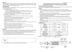
ATTENTION!
To modify configuration parameters use the program
“uprog.exe” of version 4.0.0.810 or above.
You must not use for this procedure earlier versions of “uprog.exe”
or to modify parameters by means of
S2000 or S2000М fire and alarm console.
2
INSTALLER’S AND USER’S MANUAL
PRODUCT DESCRIPTION
Table of contents
1 Product description ................................................................................ 5
1.1 Product designation ......................................................................... 5
1.2 Specifications ................................................................................... 5
1.3 The delivery set................................................................................ 9
1.4 Alarm loops ...................................................................................... 9
1.4.1
The loop configuration parameters .................................................... 10
1.4.1.1
1.4.1.2
1.4.1.3
1.4.1.4
1.4.1.5
1.4.1.6
1.4.1.7
1.4.1.8
1.4.1.9
1.4.1.10
1.4.1.11
1.4.1.12
1.4.1.13
1.4.2
Loop Type........................................................................................ 11
Arming Delay ................................................................................... 18
Intrusion/Fire Delay.......................................................................... 18
Non-disarming ................................................................................. 18
Auto Rearming When Disarmed ...................................................... 18
Auto Rearming when Fire/Alarm...................................................... 19
To Control When Disarmed ............................................................. 19
The Alarm Loop Recovery Time ...................................................... 19
Relay 1 and Relay 2 Control ............................................................ 19
Relay 1 and Relay 2 Control Delays ................................................ 19
Scheduled Arming and Disarming ................................................... 20
Loop Analysis Delay after Reset...................................................... 20
Common Zone ................................................................................. 20
Loop arming and disarming ............................................................... 22
1.5 Relays .............................................................................................. 24
1.5.1
1.5.2
1.5.3
1.5.4
Relay local control.............................................................................. 24
Relay centralized control.................................................................... 25
Turning relay on/off during access controlling ................................... 25
The relay configuration parameters ................................................... 26
1.6 Access control.................................................................................. 30
1.6.1
1.6.2
Access control configuration parameters........................................... 31
Access modes.................................................................................... 34
1.7 Double identification......................................................................... 35
1.8 Time windows .................................................................................. 36
1.9 Centralized access and partition control .......................................... 37
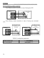
1.10 Reader connection ........................................................................... 39
1.11 Light and sound signaling ................................................................ 42
1.12 Configuration parameters ................................................................ 48
1.13 Identifiers ......................................................................................... 49
1.13.1 Identifier parameters .......................................................................... 49
1.13.2 Identifier programming ....................................................................... 51
2 Application............................................................................................. 55
3
S2000-4 INTRUSION&FIRE AND ACCEESS CONTROL PANEL
2.1 Preparation for use ...........................................................................55
2.1.1
2.1.2
2.1.3
2.1.4
Protective measures .......................................................................... 55
The panel mounting ........................................................................... 55
RS-485 interface wiring ..................................................................... 55
Changing the panel default settings .................................................. 56
2.2 Typical application ............................................................................56
2.2.1
2.2.2
2.2.3
2.2.4
Fire alarm system without access control at the small object ........... 56
Fire alarm system without access control at the large object............ 59
Burglary and fire alarm without access control.................................. 61
Burglary and fire alarm along with access control ............................. 64
3 Maintenance............................................................................................67
3.1 Panel testing .....................................................................................67
3.1.1
3.1.2
3.1.3
3.1.4
Overall functional testing ................................................................... 68
Testing in diagnostic mode ................................................................ 68
Testing of the reader connection circuits........................................... 68
Alarm loop checking .......................................................................... 68
4 Storage ....................................................................................................69
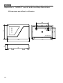
Appendix А. “S2000-4” overall and mounting dimensions........................... 70
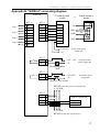
Appendix B. "S2000-4" connecting diagram................................................ 71
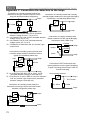
Appendix C. Connection the detectors to the loops .................................... 72
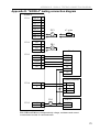
Appendix D. “S2000-4” testing connection diagram .................................... 73
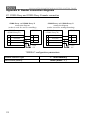
Appendix E. Reader connection diagrams .................................................. 74
E1. S2000-Proxy and S2000-Proxy N reader connection ........... 74
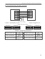
E2. Proxy-2A and Proxy-3A reader connection........................... 75
E3. PR-A03, PR-A05 or PR-P09 reader connection ................... 76
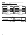
E4. PR-H03, PR-H05 or PR-M09 reader connection .................. 77
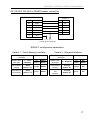
E5. Touch Memory reader connection ........................................ 78
Warranty ...................................................................................................... 79
4
INSTALLER’S AND USER’S MANUAL
PRODUCT DESCRIPTION
This Installer’s and User’s manual is intended to help for studying operability principles and maintenance of version 2.03 of S2000-4 Intrusion&Fire Alarm and Access Control Panel.
1 PRODUCT DESCRIPTION
1.1
Product designation
Intrusion&Fire Alarm and Access Control Panel S2000-4 (hereinafter
referred to as panel) is designated for usage in integrated safety systems
to protect shops, pay-offices, banks, establishments, plants and other objects from fire or intrusion threats and to meet access control needs.
The panel is intended to:
9 monitor four alarm loops with burglary and fire detectors included
9 control internal and external sounders or light alarms
9 transmit alarm signals to S2000/S2000M console or PC via RS-485
interface and to the centralized surveillance station through two relay
outputs
9 control the access with the help of Touch Memory keys and Proximity
Cards, that is to read identifiers, to check assigned authority and to
switch the contacts of relay controlling electromechanic lock.
The panel is designated for usage either in integrated “Orion” system
(based on PC supplied by at least 7 issue “ARM Orion 1.0 KD” software or
on “S2000” version at least 1.20 or “S2000M” fire and alarm console) or
stand-alone use.
The panel is to be mounted inside the premises and is destined for
clock round duration.
The panel must not be used in aggressive medium or dust condition,
or in dangerous space.
The panel is intended to be used under temperatures from 233 to 323
К (from − 40 to +50 °С).
1.2
Specifications
The panel is supplied by external direct power voltage 12V (10.2 to
14.2 V DC) or 24V (20.4 to 28.4 V DC). It is recommended to use RIP-12
or RIP-24 uninterruptible power supplies manufactured by NVP BOLID
Company.
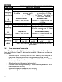
Consumed power is less 3 W.
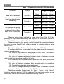
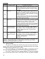
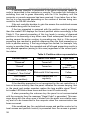
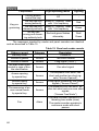
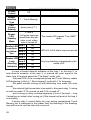
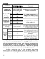
The table 1 is demonstrated the maximal consumed current in standby
and ‘Alarm’ or ‘Fire’ modes.
The maximum number of alarm loops that can be connected to is 4.
5
S2000-4 INTRUSION&FIRE AND ACCEESS CONTROL PANEL
Table 1: Consumed current in different modes
Detectors
There are no detectors
being power supplied by
loops (all detectors are
contacting)
All detectors are power
supplied by loops, with
consumed current being
equal 3 mA in each loop
Relays
Turned off
Turned on
Turned off
Turned on
Mode
Power voltage
12 V
24 V
Norm
100 mA
50 mA
Alarm/Fire
140 mA
70 mA
Norm
150 mA
75 mA
Alarm/Fire
200 mA
100 mA
Norm
130 mA
70 mA
Alarm/Fire
170 mA
85 mA
Norm
180 mA
90 mA
Alarm/Fire
220 mA
110 mA
The loop input voltage in stand-by mode varies from 19 to 24 V (depending on loop consumed current) and supports its value even in case of
short circuit failure in one of the alarm loops.
The panel restricts the electric current through the actuating detector
by value no more than 20 mA, voltage applied to actuated detector being
above 6,8 V.
The ripple voltage effective value does not exceed 20 mV.
If burglary detectors are included into the alarm loop the panel provides in standby mode:
- the value of loop resistance being equal no more than 1 kOhm without regard to external element;
- the value of leakage resistance between wires or between any wire
and ground being equal no less than 20 kOhm.
If fire detectors are included into the alarm loop the panel provides in
standby mode:
- the value of the loop resistance being equal to value no more than
100 Ohm without regard to external element;
- the value of leakage resistance between wires or between any wire
and ground being equal no less than 50 kOhm.
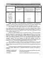
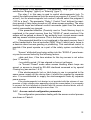
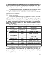
The panel supplies loop voltage for ‘Okno’, ‘Foton-8’ and ‘Volna-5’
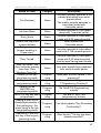
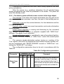
burglary detectors and for ‘DIP’ fire detector. The maximum number of one
alarm loop connected detectors is demonstrated by Table 2.
6
INSTALLER’S AND USER’S MANUAL
PRODUCT DESCRIPTION
Table 2: Maximum number of detectors connected to one loop
Detector type
Maximum number of detectors for different loop types
Fire smoke loop
Fire combined loop
Burglary
with recognition
without two detectors
alarm loop
(type 1)
activated in one loop
(type 4)
recognition (type 2)
‘Okno-4’, ‘Okno-5’
‘Folon-8’
‘Volna-5’
‘Shorokh-1’
‘Stecklo-2’
‘DIP-3M’
‘DIP-3SU’
‘DIP-U’
−
−
−
−
−
−
16
20
−
−
−
−
−
16 ( 6 )
16 ( 6 )
20 ( 8 )
40
1
1
1
1
−
−
−
Note: The value in the parentheses corresponds to the detector’s
number in case of both smoke current-consumed (normally opened) and
passive heat (normally closed) detectors being combined in one loop.
The number of other types detectors is calculated based on maximum load current being equal to 3 mA or 1,2 mA in case of type 2 alarm
loop with both smoke or heat detectors being used together. In case of
type 1 alarm loop using the detectors must retain their operability during
loop voltage dropping to 12 V.
Only one Touch Memory key, or Proximity Card, or PIN-code reader
can be connected to the panel. The reader output interface is to be Touch
Memory (1-Wire, µ-LAN), Wiegand or ABA TRACK II magnetic card interface. The panel provides the reader’s LED control with directly connected
LED current being restricted up to 10 mA. The panel supplies the reader’s
sounder control. The quit options for LED and sounder control are
5V/10mA. The distance between the panel and connected reader must not
exceed 100 m. The identifier storage capacity of the panel is 2048.
The number of control relays for locking arrangement is two with
each relay maximum switching current being equal 7 A, maximum commutating voltage being equal 30V and maximum switching power being equal
100 W.
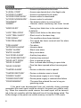
Following are the messages being transmitted by the panel to the net
controller (both “ARM Orion” or “S2000”/”S2000M” console) via RS-485 interface:
“USER’S CODE ENTR”
“ACCESS GRANTED”
“PASSED”
- The user has entered arming/disarming code
- Access was granted
- A person was passed into the access zone
7
S2000-4 INTRUSION&FIRE AND ACCEESS CONTROL PANEL
“ACCESS DENIED”
“ILLEGAL CODE”
“ACCESS CLOSED”
“ACCESS FREE MODE”
“ACCESS NORM MODE”
“DISARMED”
“ARMED”
“FIRE ALARM”
“INTRUSION ALARM”
- Access is prohibited for this code
- Access was denied due to the illegal code
- Access is prohibited for all codes
- Access control is deactivated
- Access control is activated
- The detector status is not monitored
- Detector status monitoring has been turned
on
- Arming has failed due to the activated status
of detector
- Open-circuit failure in the alarm loop
- Short circuit in the alarm loop
- Fire conditions have been detected
- Fire signal has been received and fire alarm
is probable
- Fire alarm
- Intrusion alarm
“SILENT ALARM”
- Silent zone alarm
“ENTRY ALARM”
“AUX ZONE ALARM”
“AUX ZONE RESTORY”
“DOOR LEFT OPEN”
“DOOR CLOSED”
- Entry zone alarm
- Auxiliary loop alarm
- Auxiliary loop restored
- Door is opened too long
- Door is closed after blocking in open state
- Door has been opened without access granting
“ARM FAILED”
“LOOP TRBL OPEN”
“LOOP TRBL SHORT”
“FIRE SIGNAL”
“FIRE PREALARM”
“DOOR FORCED”
“TAMPER ALARM”
- Device or detector case is opened
“TAMPER RESTORE”
- Device or detector case is closed
“POWER FAILED”
- Device power supply is out of range
“POWER RESTORE”
“PROGRAMMING”
- Device power supply is restored after failure
- The panel has entered the user’s key programming mode
If the panel was disconnected from net controller during message
generation the event report would be stored in the panel non-volatile memory. When the connection would recover the event report will be transmitted to the net controller with the date and time of its origin being noted. The
buffer storage in the panel non-volatile memory is sized to 1023 events.
8
INSTALLER’S AND USER’S MANUAL
PRODUCT DESCRIPTION
The panel executes several commands having been received via RS485 interface, which are configuration writing, net address assigning, loop
arming/disarming, relay control, access control, access identifier reading,
access identifier adding or changing, time synchronization or reading the
non-dimensional loop resistance value given by digital-to-analog converter.
The panel uptime after power-on does not exceed 3 seconds.
The panel mean life is 20 000 hours.
The panel average operating life is 8 years.
The mass of the panel is about 0,3 kg, with overall dimensions being
equal to 150×105×35 mm.
The panel construction design provides the ingress protection rating
in accordance with IP20.
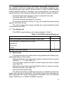
1.3
The delivery set
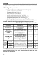
The S2000-4 panel delivery set is demonstrated in Table 3.
Table 3: The S2000-4 panel delivery set
Designation
S2000-4 Intrusion&Fire Alarm and Access Control Panel
Number
1
The replacement component set including:
Resistances
4
Screw nails
3
Dowels
3
Installer’s and User’s Manual
1
1.4
Alarm loops
The panel monitors four alarm loops and generates the following signaling depending on their status:
displays the alarm loop statuses by means of internal two-color panel
indicators “1” – “4” (see Table 14)
turns the panel internal sounder on when loops have been troubled
(see Table 15)
displays the loop status with the highest priority by means of reader
two-color indicator (see Table 13)
controls the two panel relays.
The alarm loop status is defined by its type, its resistance and by the
logical state (armed or disarmed). The status having been changed, the
panel generates and sends corresponding messages to the net controller
(either “ARM Orion” or “S2000”/”S2000M” console).
9
S2000-4 INTRUSION&FIRE AND ACCEESS CONTROL PANEL
1.4.1
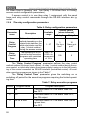
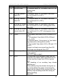
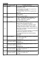
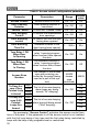
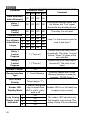
The loop configuration parameters
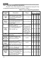
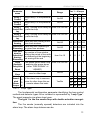
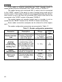
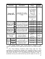
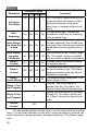
The alarm loop control algorithm can be changed by varying the loop
configuration parameters that can be viewed in Table 4.
Table 4: Loop configuration parameters
Parameter
name
Description
Determines the control algorithm, available types of detectors to be connected and potential statuses
The time interval between havArming ing received arming command
and loop transition to the
Delay
“armed” status
The delay for transitions from
“ENTRY ALARM” to
“INTRUSION ALARM” state or
Intrusion/ from “FIRE PREALARM” to
Fire
“FIRE ALARM” one
Delay
Loop
Type
Nondisarming
Auto Rearming
When Disarmed
Auto Rearming
When
Fire/Alarm
To Control
When Disarmed
The Alarm
Loop Recovery
Time
10
The loop cannot be disarmed
by any way
Auto transition from “ARM
FAILED” to “ARMED” when
loop having recovered
Range
Default value
for 1 – 4 loops
1
2
3 4
1…7, 11,12
7
4
4
1
from 0 to 255 sec
60
0
0
0
from 0 to 254 sec
255 means Off
(one detector having been acti30
vated, it must not
transit “Fire
Alarm” or “Intrusion Alarm”)
0
0
120
On/Off
Off Off Off Off
On/Off
Off Off Off On
Auto transition from “FIRE”,
“INTRUSION ALARM” or
“SILENT ALARM” to “ARMED”
when loop having recovered
On/Off
Off Off Off Off
To monitor and transmit the
resistance changes (is its normal or not) via RS-485
On/Off
Off Off Off Off
The time of making the decision that loop has recovered in
case of “Auto Rearming when
Fire/Alarm”, or transition to
“Aux Zone Restore” status, or
disarmed loop control
from 0 to 255 sec
15
15
15
15
INSTALLER’S AND USER’S MANUAL
Parameter
name
Relay 1
Control
Relay 2
Control
Relay 1
Control Delay
Relay 2
Control Delay
Scheduled
Arming
Scheduled
Disarming
Time Window for
Scheduled
Arming/
Disarming
Loop
Analysis
Delay after
Reset
Common
Zone
List of 1
Associ- 2
ated
3
Alarm
Loops 4
Description
PRODUCT DESCRIPTION
Range
Default value
for 1 – 4 loops
1
2
3 4
Assign relay 1 to the particular
On/Off
On On On On
loop
Assign relay 2 to the particular
On/Off
On On On On
loop
Relay 1 turning on/off delay for from 0 to 255 sec 0
0
0
0
a particular loop
Relay 2 turning on/off delay for from 0 to 255 sec
a particular loop
Alarm loop auto arming at the
given time windows
Alarm loop auto disarming at
the given time windows
The number of time window
defining the period of time with
the disarming at the beginning
and arming at the end
The pause before alarm loop
analysis after power dump
(when “FIRE SIGNAL” or
“ARMED”)
The alarm loop is common
zone for other loops
If the alarm loop is common
zone for other loops this parameter shows that ones
0
0
0
0
On/Off
Off Off Off Off
On/Off
Off Off Off Off
from 0 to 15
0
0
0
0
from 0 to 255 sec
2
2
2
2
On/Off
Yes/No
Off Off Off Off
− No No No
No − No No
No No − No
No No No
−
1.4.1.1 Loop Type
The fundamental configuration parameter identifying the loop control
method and detector types to be included is represented by “Loop Type”.
The panel supports nine alarm loop types.
The type 1 is the fire smoke loop with double actuation recognition.
The fire smoke (normally opened) detectors are included into the
alarm loop. The alarm loop statuses can be:
11
S2000-4 INTRUSION&FIRE AND ACCEESS CONTROL PANEL
“Armed” – the alarm loop is monitored and the resistance is in normal
range.
“Disarmed” - the alarm loop is not monitored.
“Arming delay” – the arming delay has not yet been elapsed.
“Fire prealarm” – the single detector actuation has been fixed.
“Fire alarm” - actuating more than one detector has been fixed, or after first detector actuation the Intrusion/Fire delay has expired.
“Loop trbl short” – the alarm loop resistance is less than 100 Ohm.
“Loop trbl open” - the alarm loop resistance is more than 6 KOhm.
“Arm Failed” – the alarm loop was broken when arming.
When detector has actuated the panel generates the “Fire Signal”
message and de-energizes the alarm loop for a short time. If within 55 seconds after de-energizing the detector connected to this loop repeats actuation the panel enters the “Fire Prealarm” mode at given loop. If the second
actuating has not occurred within 55 seconds the alarm loop returns to the
“Armed” state. From the “Fire Prealarm” mode the panel can transit to the
“Fire alarm” mode if the second detector has been actuated or Intrusion/Fire delay has expired at this loop. If Intrusion/Fire delay was given as
0 then the transition from “Fire prealarm” to “Fire alarm” mode would happen instantly. If Intrusion/Fire delay was given as maximum value 255 then
the transition from “Fire prealarm” to “Fire alarm” would be able only after
actuating of the second detector at one loop.
The type 1 alarm loop resolving time is 300 ms.
The compatibility of loop resistance and the corresponding status can
be shown at the Table 5.
The diagram of connection the fire smoke (normally opened) detectors to the type 1 alarm loop is contained into the Appendix C.
The type 2 is the fire combined alarm loop.
The fire smoke (normally opened) and heat (normally closed) detectors are included into the alarm loop. The alarm loop statuses can be:
“Armed” – the alarm loop is monitored and the resistance is in normal
range.
“Disarmed” - the alarm loop is not monitored.
“Arming delay” – the arming delay has not yet been elapsed.
“Fire prealarm” – the heat detector actuation or second smoke detector actuation has been fixed.
“Fire alarm” - after detector actuation the Intrusion/Fire delay has expired.
“Loop trbl short” – the alarm loop resistance is less than 100 Ohm.
“Loop trbl open” - the alarm loop resistance is more than 50 KOhm.
12
INSTALLER’S AND USER’S MANUAL
PRODUCT DESCRIPTION
“Arm Failed” – the alarm loop was broken when arming.
When heat detector has actuated the panel enters the “Fire
Prealarm” mode. When smoke detector has actuated the panel generates
“Fire Signal” message and de-energizes the alarm loop for a short time. If
within 55 seconds after de-energizing the detector connected to this loop
repeats actuating the panel enter the “Fire Prealarm” mode at given loop. If
the second actuation of smoke detector has not occurred within 55 seconds the alarm loop returns to the “Armed” state. From the “Fire Prealarm”
mode the panel can transit to the “Fire alarm” mode if Intrusion/Fire delay
has expired. If Intrusion/Fire delay was given as 0 then the transition from
“Fire prealarm” to “Fire alarm” mode would happen instantly. If Intrusion/Fire delay was given as maximum value 255 then the transition from
“Fire prealarm” to “Fire alarm” would be impossible.
The type 2 alarm loop resolving time is 300 ms.
The compatibility of loop resistance and the corresponding status can
be shown at the Table 5.
The diagram of connection the fire smoke (normally opened) and
heat (normally closed) detectors to the type 2 alarm loop is contained into
the Appendix C.
The type 3 is the fire heat loop with double actuation recognition.
The fire heat (normally closed) detectors are included into the alarm
loop. The alarm loop statuses can be:
“Armed” – the alarm loop is monitored and the resistance is in normal
range.
“Disarmed” - the alarm loop is not monitored.
“Arming delay” – the arming delay has not yet been elapsed.
“Fire prealarm” – the one detector actuation has been fixed.
“Fire alarm” - actuating more than one detector has been fixed, or after one detector actuation the Intrusion/Fire delay has expired.
“Loop trbl short” – the alarm loop resistance is less than 2 KOhm.
“Loop trbl open” - the alarm loop resistance is more than 50 KOhm.
“Arm Failed” – the alarm loop was broken when arming.
When the detector in such alarm loop has actuated the panel enters
the “Fire Prealarm” mode. The panel enters the “Fire Alarm” mode from
“Fire Prealarm” if the second detector has activated at this loop or Intrusion/Fire delay has been expired. If Intrusion/Fire delay was given as 0
then the transition from “Fire prealarm” to “Fire alarm” mode would happen
instantly. If Intrusion/Fire delay was given as maximum value 255 then the
transition from “Fire prealarm” to “Fire alarm” would be able only if the second detector in this loop has actuated.
13
S2000-4 INTRUSION&FIRE AND ACCEESS CONTROL PANEL
The type 3 alarm loop resolving time is 300 ms.
The compatibility of loop resistance and the corresponding status can
be shown at the Table 5.
The diagram of connection the heat (normally closed) detectors to the
type 3 alarm loop is contained into the Appendix C.
The type 4 is the burglary alarm loop.
The alarm loop includes burglary detectors of all types, including normally closed, normally opened, powerless, supplied via alarm loop or separately.
The alarm loop statuses can be:
“Armed” – the alarm loop is monitored and the resistance is in normal
range.
“Disarmed” - the alarm loop is not monitored.
“Arming delay” – the arming delay has not yet been elapsed.
“Intrusion alarm” – the detector breaking has been fixed.
“Arm Failed” – the alarm loop was broken when arming.
The intrusion alarm loop is considered as broken if its resistance has
been out of 2…6 KOhm range when arming or having been armed, or resistance jump more than 10% when the loop is armed. The breaking of the
armed loop leads this one to the “Intrusion Alarm” status.
The type 4 alarm loop resolving time is 70 ms.
The compatibility of loop resistance and the corresponding status can
be shown at the Table 5.
The diagram of connection burglary detector to the type 4 alarm loop
is contained into the Appendix C.
The type 5 is the burglary alarm loop with tamper check.
The alarm loop includes burglary detector with normally closed contacts and tamper detector.
The alarm loop statuses can be:
“Armed” – the alarm loop is monitored and the resistance is in normal
range.
“Disarmed” - the alarm loop is not monitored.
“Arming Delay” – the arming delay has not yet been elapsed.
“Intrusion Alarm” – the detector breaking has been fixed.
“Arm Failed” – the alarm loop was broken when arming.
“Tamper Alarm” – the loop being disarmed, the tamper has actuated.
When alarm loop is armed the detector actuation (opening of its burglary contact) or tamper actuation switches the loop to the “Intrusion Alarm”
mode. When alarm loop is not armed (being in statuses “Disarmed”, “Arm
14
INSTALLER’S AND USER’S MANUAL
PRODUCT DESCRIPTION
delay” or “Arm failed”) tamper actuation switches the loop to the “Tamper
Alarm” status.
The type 5 alarm loop resolving time is 70 ms.
The compatibility of loop resistance and the corresponding status can
be shown at the Table 5.
The diagram of connection burglary detector with tamper check to the
type 5 alarm loop is contained into the Appendix C.
The type 6 is the auxiliary alarm loop.
The auxiliary alarm loop is intended to control the door status in gas
fire extinguishing systems, to control the status, actuations and operability
of extinguishing equipment and to control the detectors or other equipment
independent from burglary or fire alarming. The detectors or devices with
“dry contact” output (normally opened or closed), or with “open collector”
output are included in alarm loop of this type.
The alarm loop statuses can be:
“Aux Zone Alarm”;
“Aux Zone Restore”.
If the alarm loop resistance has come out of 2…6 kOhm range for
more than 300 ms the loop has entered the “Aux Zone Alarm” status. The
loop resistance having been within 2…6 kOhm range for more than “The
Alarm Loop Recovery Time” sec, the loop has entered the “Aux Zone Restore” status. The auxiliary alarm loop is impossible to disarm, it is monitored permanently. Having received the arming/disarming command the
panel generates the current loop status message.
Alarm loop status having been changed, the corresponding messages are sent to the net controller (“S2000”/”S2000-M” console or “ARM
Orion”). These messages are not storied in non-volatile panel memory. So
if during net controller disconnection several status changes had occurred
then when connection recovering either only one message would be sent
to the net controller or no messages would be sent if the current status is
equal the last sent one.
Auxiliary alarm loop being associated with a relay, it failure blocks up
the relay turning on assigning to the 1-8, 11, 12, 33, 34, 35 programs (see
1.5.1 section of this Manual). This feature can be used, for example, for
creating the gas fire extinguishing system with launch blocking dealing with
opened door to the protected premises.
The compatibility of loop resistance and the corresponding status can
be shown at the Table 5.
The connection of normally opened or normally closed detectors and
other controlled “dry contact” circuits to the type 6 alarm loop is identical to
the connection of burglary detectors to type 4 loop (see Appendix C).
15
S2000-4 INTRUSION&FIRE AND ACCEESS CONTROL PANEL
The type 7 is the entering alarm loop.
All types of burglary detectors, including opening or closing, powerless or power supplied via alarm loop or separately are included into the
type 7 alarm loop.
The alarm loop statuses can be:
“Armed” – the alarm loop is monitored and the resistance is in normal
range.
“Disarmed” - the alarm loop is not monitored.
“Arming Delay” – the arming delay has not yet been elapsed.
“Entry Alarm” – the loop breaking has been fixed.
“Intrusion Alarm” – after having entered “Entry Alarm” status the “Intrusion/Fire Delay” period has expired.
“Arm Failed” – the alarm loop was broken when arming.
The performance and parameters of entering alarm loop are identical
to those of type 4 burglary alarm loop, except that breaking of armed loop
transits it at first to the “Entry Alarm”, and only if during the “Intrusion/Fire
Delay” period arming or disarming of the alarm loop had not occurred it
would enter to the “Intrusion Alarm” status.
While the alarm loop is in the “Entry Alarm” status the relay switching
by means of executive programs 1 – 8 and 12 does not perform.
This type alarm loop resolving time is 70 ms.
The compatibility of loop resistance and the corresponding status can
be shown at the Table 5.
The diagram of connection burglary detectors to the type 7 alarm
loop is contained into the Appendix C.
The type 11 is the alarming loop.
The alarm loop includes normally opened and normally closed alarm
devices (call points, footboards and so on).
The alarm loop statuses can be:
“Armed” – the alarm loop is monitored and the resistance is in normal
range.
“Disarmed” - the alarm loop is not monitored.
“Arming Delay” – the arming delay has not yet been elapsed.
“Silent Alarm” – attack, the alarm loop breaking has been detected.
“Arm Failed” – the alarm loop was broken when arming.
The alarming loop is considered as broken if its resistance is out of
2…6 kOhm range. When breaking in armed status the alarming loop enter
the “Silent alarm” status. This status is indicated only by inner panel LED 14 and influences the relay controlled by means of 10 program (“Alarm output 1”) or 16 program (“Alarm output 2”) with relay being opened. The inner
16
INSTALLER’S AND USER’S MANUAL
PRODUCT DESCRIPTION
audible sounders of panel and reader don’t make sounds and reader LED
don’t change it status.
This type 11 alarm loop resolving time equal 300 ms.
The compatibility of loop resistance and the corresponding status can
be shown at the Table 5.
The diagram of connection call points and other alarm annunciators
to the type 11 alarm loop is contained into the Appendix C.
The type 12 is the programmable auxiliary alarm loop.
This type alarm loop can be used to control the variety of equipment,
among them the devices not dealing with burglary or fire alarming.
The detectors or devices with “dry contact” output (normally opened
or closed), or with “open collector” output are included in alarm loop of this
type. The programmable auxiliary alarm loop can have up to 5 various
statuses that are defined by loop resistance. One can program both
statuses and the corresponding threshold resistance values. In so manner
the equipment having several statuses and associated output contact
groups can be monitored by means of one alarm loop if groups are included into alarm loop along with additional or shunt resistances. Moreover
one can control short or open failures of this loop.
Audible and light alarming and the influence of this loop to the relay
are defined by the statuses this alarm can have.
Status changing of the programmable auxiliary alarm loop depends
only on the alarm loop resistance changing and is not defined by any loop
parameters or arming/disarming commands.
The resolving time in case of status changing is equal to 300 ms. If
alarm loop is entering “Armed”, “Disarmed”, “Aux Zone Restore” or one of
recovering statuses then the transition is considered as completed in "The
Alarm Loop Recovery Time" seconds.
The programmable auxiliary alarm loop is impossible to disarm, it is
monitored permanently. Received the programmable auxiliary loop arming/disarming command the panel generates the current loop status message.
Programmable auxiliary alarm loop status having been changed, the
corresponding messages are sent to the net controller (“S2000”/”S2000-M”
console or “ARM Orion”). These messages are not storied in non-volatile
panel memory. So if during net controller disconnection several status
changes had occurred then when connection is recovered either only one
message would be sent to the net controller or no messages would be sent
if the current status is equal the last sent one.
17
S2000-4 INTRUSION&FIRE AND ACCEESS CONTROL PANEL
1.4.1.2 Arming Delay
The parameter "Arming Delay" means the "exiting duration" or the
number of seconds you want the panel to wait before arming the alarm
loop after having received the corresponding command. Nonzero "Arming
Delay" is normally used for entering alarm loop in case of after entering
arming command it is possible for some time to break this loop without going off an alarm. If before loop arming it is necessary to turn relay on (the
executive program 17 “Turn on for a given time before arming”) then the
“Arming delay” loop parameter has to be set to a nonzero value. Otherwise
the relay will not turn on because of the turning time for this program must
not exceed the “Arming delay” loop parameter.
1.4.1.3 Intrusion/Fire Delay
For entering alarm loop (type 7) the “Intrusion/Fire Delay” parameter
means the transition delay from “Entry Alarm” to “Intrusion Alarm” status
and is considered as “entering duration”. “Intrusion/Fire Delay” is given to
make it possible to disarm alarm loop after entering loop breaking.
For entering alarm loop (types 1, 2, 3) the “Intrusion/Fire Delay” parameter means the period of loop transition from “Fire prealarm” to “Fire
alarm” status. Alarm loops with double actuation recognition (types 1 and
3) can transit to the “Fire alarm” status when second fire detector in this
loop has actuated. If “Intrusion/Fire Delay” is set to 255 s it means unlimited delay when the panel does not enter to the “Fire Prealarm” status due
to the time conditions. In this case type 1 or 3 alarm loop can enter the
“Fire Alarm” status only along with second loop detector actuation, but type
2 alarm loop can not enter the “Fire Alarm” status under any conditions.
1.4.1.4 Non-disarming
The parameter "Non disarming" prohibits loop disarming. This parameter is used to prevent fire or alarming loop incident disarming. If alarm
loop is entering “Intrusion Alarm”, “Silent Alarm”, “Fire Prealarm”, “Fire
Alarm” or “Arm Failed” statuses then arming and disarming of the alarm
loop will lead to attempt to arm this loop (“ALARM RESET”). As a result the
alarm loop will enter the “Armed” status (the loop resistance is within the
normal range) or the “Arm Failed” status (the alarm loop is broken).
1.4.1.5 Auto Rearming When Disarmed
When the alarm loop has entered the “Arm Failed” status (the loop
was broken when arming) and if the parameter “Auto Rearming When
Disarmed” is set for this alarm loop then the alarm loop will automatically
enter the “Armed” state when it resistance will be in normal range.
18
INSTALLER’S AND USER’S MANUAL
PRODUCT DESCRIPTION
1.4.1.6 Auto Rearming when Fire/Alarm
When the alarm loop has entered the “Intrusion Alarm”, “Silent Alarm”
or “Fire Alarm” statuses and the parameter “Auto Rearming When
Fire/Alarm” is set then the alarm loop will automatically enter the “Armed”
state when it resistance will be in normal range during “The Alarm Loop
Recovery Time” period.
1.4.1.7 To Control When Disarmed
The parameter “To Control When Disarmed” makes the panel to
control alarm loops in all statuses including “Disarmed”. If the alarm loop
resistance is in normal range the message “Ready to Arm” is sent for net
controller, if not the panel sends the “Not Ready to Arm” message for the
net controller. The resolving time for “Not Ready to Arm” is 300 ms and for
“Ready to Arm” is equal to the “The Alarm Loop Recovery Time”.
1.4.1.8 The Alarm Loop Recovery Time
“The Alarm Loop Recovery Time” is used when making the decision about loop having been recovered in case of “Auto Rearming when
Fire/Alarm”, or transition to “Aux Zone Restore” status, or transition of disarmed auxiliary loop to the “Aux Zone Restore” status.
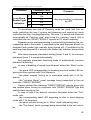
1.4.1.9 Relay 1 and Relay 2 Control
The parameters “Relay 1 Control” and “Relay 2 Control” are associated the alarm loop with the panel relays. If relay 1 or/and relay 2 state
must be influenced by the alarm loop then the corresponding parameter
must be set otherwise it must be turned off.
If relay 1 or relay 2 must be controlled depending on the loop partitions
status in accordance with the assigned program given by
“S2000”/”S2000M” or “ARM Orion” (in case of centralized control) then parameters “Relay 1 Control” and “Relay 2 Control” have to be turned off
even though this alarm loop is included to the partition affecting upon the
panel relay.
1.4.1.10 Relay 1 and Relay 2 Control Delays
If the alarm loop status changing is to lead to the relay switching in
accordance with the executive relay programs then turning relay 1 or 2 on
(off) takes place not at once but after some “Relay 1 Control Delay” or
“Relay 2 Control Delay” period given for this alarm loop. For the executive
programs 9, 10, 13, 14, 15 and 16 (see the Table 7) these parameters are
ignored and relays switches straight after the alarm loop status having
been changed.
19
S2000-4 INTRUSION&FIRE AND ACCEESS CONTROL PANEL
1.4.1.11 Scheduled Arming and Disarming
The parameters “Scheduled Arming” and “Scheduled Disarming”
turn loop auto arming and disarming on at the given time. To give the time
of auto arming or auto disarming the parameter “Time Window for scheduled arming/disarming” is used.
At a moment when the ”Time Window For Scheduled Arming/Disarming” has been active the loop is disarmed (if “Scheduled Disarming” is on). When the ”Time Window For Scheduled Arming/Disarming” has
been finished the loop disarming is tried on.
Scheduled Arming and Disarming are enabled only in networking operation mode of the panel as a part of “Orion” system, with the panel date
and time being synchronized.
If during the alarm loop arming it resistance is less than normal value,
for example, if the smoke fire detector has actuated at the alarm loop, then
the panel automatically resets this loop, that is, de-energizes all loops for 3
sec. In addition the panel resets the loop after the first normally opened
(smoke) detectors actuation at the alarm loop of type 1 or type 2.
1.4.1.12 Loop Analysis Delay after Reset
The “Loop Analysis Delay after Reset” parameter enables to include the detectors with long warm-up time (or long reading time) in the
alarm loop. If the loop power supplied detectors enters to the operational
mode (and requires higher current consumption) during long time after loop
resetting than it is necessary to set the “Loop analysis delay after reset”
parameter to the value just over maximum warm-up time of loop included
detectors.
1.4.1.13 Common Zone
The “Common Zone” parameter enables auto disarming of loop
when any other associated alarm loop has been disarmed. Moreover it enables auto arming of loop when all associated alarm loops has been
armed. Except the “Common Zone” parameter the parameter “The List of
Associated Alarm Loops” is defined for the alarm loop.
If the “Common Zone” parameter is set for the alarm loop then this
loop arming and disarming depend on the arming and disarming of the related loops. If at least one of the related loops has been disarmed then the
present loop is disarmed too. If all related loops have been armed then this
loop enters the armed status. It is not possible to change the common zone
status by arming/disarming via RS-485 interface or with the help of identifiers. If alarm loop from common zone has the “Intrusion Alarm” status the
arming/disarming command leads to the arming of this loop (“ALARM
RESET” status).
20
INSTALLER’S AND USER’S MANUAL
PRODUCT DESCRIPTION
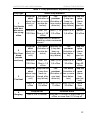
Table 5: Loop parameters depending on the status
Loop type
Alarm loop statuses
Loop trbl
short
Fire alarm
Loop trbl
short
Fire alarm
Loop trbl
short
Loop trbl rst
Fire
prealarm
Loop trbl rst Loop trbl
open
(Loop has
(Actuation of
(alarm loop two or more (Actuation of been re(alarm
smoke de- one smoke stored after
short cirloop
1
tectors)
any failure) open circuit)
detector)
Fire Smoke
cuit)
with double actua- less then
above
from 150
from 1,1* to from 2,4 to
*
tion recog- 100 Оhм Оhм to 1,56
5,4 кОhм 6,6 кОhм
2,0 кОhм
nition
кОhм
* Depending on detector
stand-by mode consumed
current
Loop trbl rst
Fire
prealarm
Loop trbl
open
(Actuation of (Loop has
2
been re- (Actuation of (alarm
(alarm loop smoke detector)
stored after heat detecshort cirloop
Fire Combined
any failure)
cuit)
tor)
open cir(smoke
cuit)
and heat)
less then
from 150
from 2,2 to from 6,6 to
more
100 Оhм Оhм to 1,8
5,4 кОhм
30 кОhм
than 50
кОhм
кОhм
3
Fire Heat
4
Burglary
Fire
prealarm
Fire alarm
Loop trbl
(Actuation of open
(Loop has
(alarm loop been re- (Actuation of two or more (alarm
heat detecshort cir- stored after
one heat
loop
any failure)
tors)
cuit)
detector)
open circuit)
less 1,8
from 2,2 to from 6,6 to from 12,5 to
more
кОhм
5,4 кОhм
11 кОhм
30 кОhм
than
50 кОhм
Loop trbl rst
Intrusion alarm
from 2,2 to 5,4 кОhм
less than 1,8 кОhм, or more than 6,6
кОhм, or more than 10 % hop off
21
S2000-4 INTRUSION&FIRE AND ACCEESS CONTROL PANEL
Loop type
5
Burglary
with tamper check
6
Auxiliary
Alarm loop statuses
Loop trbl rst
from 2,2 to
5,4 кhОм
Intrusion alarm
Tamper alarm
less than 1,8 кОhм, from 6,6 кОhм to 9,0 кОhм
or more than 20 кОhм
or more than 6,6
кОhм
(in "Armed", "Arm delay" or
(in "Armed" status)
"Arm failed" statuses)
Aux zone restore
Aux zone alarm
from 2,2 to 5,4 кОhм
less then 1,8 кОhм or more than
6,6 кОhм
7
Entering
Loop trbl rst
Entry alarm
from 2,2 to 5,4 кОhм
less then 1,8 кОhм or more than
6,6 кОhм, or more than 10 % hop
off
11
Alarming
Loop trbl rst
Silent alarm (attack)
less then 1,8 кОhм or more than
6,6 кОhм
12
Auxiliary
Programmable
1.4.2
from 2,2 to 5,4 кОhм
Status 1*
Status 2*
Status 3*
Status 4*
*
*
*
Status 5*
less then
from R1
from R2
from R3
more than
*
*
*
*
R1
to R2
tо R3
tо R4
R4*
* - alarm loop statuses and threshold resistances are programmable
Loop arming and disarming
Fire (types 1, 2 or 3) alarm loops, burglary (types 4, 5 and 7) alarm
loops and entering (type 11) alarm loops are able to be armed or disarmed
as follows:
− With the help of Proximity card or Touch Memory key assigned by
user code controlling this loop arming/disarming (local control);
− By the arming/disarming command from net controller via RS-485
interface (centralized control);
− Scheduled arming/disarming (auto control);
− Common zone arming/disarming in case of arming/disarming of related loops (auto control);
− Auto rearming when disarmed (auto control);
− Auto rearming when fire/alarm (auto control).
22
INSTALLER’S AND USER’S MANUAL
PRODUCT DESCRIPTION
If the loop “Non-disarming” parameter is set on then this loop can not
be disarmed. When arming/disarming command for non-disarming loop
has been received through RS-interface:
− If been armed this loop retains it status and sends the message
“Armed” to the net controller;
− If been in “Alarm”, “Fire Alarm” or “Arm Failed” statuses this loop is
armed and enters the “Armed” status in case of normal resistance
value or in “Arm Failed” statuses otherwise.
For arming/disarming with the help of Proximity card or Touch Memory key it is necessary to program this key or card with the “User Code” attribute and the list of arming/disarming available loops (see 1.13.1).
When the identifier is presented to the reader all loops controlled by
this identifier are armed if they all have “Disarmed” status, or are all disarmed otherwise.
The combined (using for arming/disarming and for access control)
identifiers in standard mode are used for access control. To arm or disarm
with the help of this identifier one has to switch the reader to the “Arming/Disarming Readiness” mode. To do this press the “Arming Request”
button (the button closes the “D0” circuit to the “GND” circuit) and hold
more than 1 s until the reader LED flashes. Instead of “Arming Request”
pressing one can close two Touch Memory reader terminals for the same
time and after that during 30 s reader light pulsing the combined identifier
will be considered as arming/disarming one. The “Arming/Disarming
Readiness” mode operates only for one reading and switches off after presenting the identifier, or after 20 s, or in case of repeated “Arming Request”
button pressing (reader terminals closing).
If there are access blocking armed alarm loops (the access control
parameter “Armed loop access blocking” is on) then when presenting of the
combined identifier without “Arming/Disarming Readiness” mode switching
on the loop will be disarmed and the access will be gained simultaneously
(if identifier authority level are enabled to disarm access blocking alarm
loops). So it is necessary to switch the “Arming/Disarming Readiness” on
only when arming by means of combined identifier, with disarming being
realized after first combined card access gaining.
Arming/disarming by means of combined identifier is possible without
“Arming/Disarming Readiness” mode transit. For this purpose one should
give non-zero value for the “Combined Identifier Holding Time” reader parameter. If the combined identifier is presented to the reader and is held for
some time then the corresponding alarm loops are armed or disarmed.
Short-time presenting of combined identifier leads to access gaining, with
relay turning on and access gaining message generation being realized
with some delay after identifier disappearing. This arming/disarming
method can be used only for Touch Memory interface reader.
23
S2000-4 INTRUSION&FIRE AND ACCEESS CONTROL PANEL
If “Combined Identifier Holding Time” is set to zero then the method
mentioned above is disabled and the panel gains the access instantly after
combined identifier presenting.
The arming/disarming can be realized by the corresponding commands sending via RS-485 interface from PC, “S2000”/”S2000M” console
or one of the safety system “Orion” devices using the partition arming/disarming mechanism. Moreover to control fire and burglary alarm system one can use “S2000-4” panel (see section 1.9).
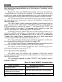
1.5
Relays
The panel relays can be controlled by one of the following ways:
- Local control in accordance with the assigned executive program
depending on the connected alarm loop status.
- Centralized control by means of commands sent by net controller
via RS-485 interface.
- Turning relays on/off for a given time while accessing process.
1.5.1
Relay local control
To control the relay depending on connected alarm loop status it is
necessary to:
- assign the relays with the corresponding loops by means of “Relay 1
Control” and “Relay 2 Control” loop parameters;
- give the “Relay 1 Control Delay” and “Relay 2 Control Delay” loop
parameters;
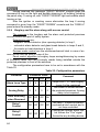
- assign the “Relay Control Program” and “Relay Control Time” relay parameters for relay 1 and relay 2.
The “Relay Control Program” parameter defines the relay behavior depending on the related loop statuses. All available executive programs are
represented in Table 7.
The “Relay Control Time” parameter gives the period of time required
by executive programs with the limited duration.
Except the programs №№ 9, 10, 13, 14, 15, 16 (see Table 7) all other
programs support the delayed relay turning on/off for time interval given by
“Relay Control Delay” parameter for the corresponding loop. So different
panel alarm loops associated with the same relay can be given by different
starting delays.
For executive programs from 1 to 8, 11, 12, 33, 34, 35 the relay assigned auxiliary loop (type 6) breaking blocks up the relay turning on. If
when auxiliary loop recovering the turning on condition depending on the
other loops are retained then for the programs 1, 2, 5, 6, 12 and 33 the relay switching on will be resumed, but for the programs 3, 4, 7, 8, 34 and 35
the switching will not be on. Thus, the auxiliary loop breaking holds the time
24
INSTALLER’S AND USER’S MANUAL
PRODUCT DESCRIPTION
unlimited programs along with programs 11 and 33 and cancels time restricted programs along with programs 12, 34 and 35.
If the panel loops are assigned with the relays then control commands via RS-485 interface will be ignored and the local relay control will
be in use.
1.5.2
Relay centralized control
To control the relays via RS-485 interface it is necessary to:
- Turn off the “Relay 1 Control” and “Relay 2 Control” loop parameters
- Define the executive program with the corresponding initial relay
status (turned on or off)
- Assign this relays with the corresponding partition in the net controller configuration, define the executive program, give the control delay and the control time
In case of relays being not assigned with the loops the “Relay Control
Program” parameter defines only the initial status of relay, that is the status
which relay will be set to under the power turning on until the first centralized command will be received. Usually the programs with “turned off” initial statuses are used, for example, the program 1 “Turn on”.
After the power turning the centralized control command can be received after some time so if centralized command supposes the turned on
initial statuses it makes sense to switch relay on immediately after power
turning on. In such a case it is necessary to give the relay any executive
program assuming the initial turned on status, for example, the program 2
“Turn off”.
1.5.3
Turning relay on/off during access controlling
When the access control is in use it is necessary to give the “Relay
Controlling Program” and the “Relay Control Time” for the relay 1.
The “Relay 1 Controlling” loop parameter defines if the relay 1 turns
on or not during access controlling.
Only the executive programs 3 (“On for a time”) and 4 (“Off for a
time”) are available.
The executive programs 3 (“On for a time”) is used for electromechanical locks or latches controlling. Initially the relay is off but in case of
access gaining the relay is turning on (closing) for a given time.
The executive programs 4 (“Off for a time”) is used for electromagnetic locks or latches controlling. Initially the relay is on but in case of access gaining the relay is turning off (opening) for a given time.
The “Relay 1 Control Time” parameter defines the maximum turning
on (off) time when access gaining. The actual relay 1 control time when access gaining can be less or equal to the pointed time (see “Turn Relay 1
25
S2000-4 INTRUSION&FIRE AND ACCEESS CONTROL PANEL
Off When Door Is Opening” and “Turn Relay 1 Off When Door Is Closing”
access control configuration parameters).
If access control is in use then relay 1 assignment with the panel
loops and relay control commands through the RS-485 interface are ignored.
1.5.4
The relay configuration parameters
Table 6: Relay configuration parameters
Parameter
name
Description
Relay
Control
Program
Defines the relay control
method depending on the
related loop statuses, the
initial relay status and the
relay 1 control method
during the access control
Relay
Control
Time
The switching on or off
period for the executive
programs with restricted
operating time
Available
range
Default values
(when delivered)
Relay1
Relay 2
1…37
3
“On for a
time”
10
“Alarm output 1”
from 1 to
8192 s in
increments
of 1/8 s
100
0
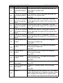
The “Relay Control Program” parameter defines the relay control
method realized via loops (local control), or relay 1 control method during the access control, or initial relay status from power supply turning on to the first receiving of the control command via RS-485 interface (centralized control). All available executive programs are shown in the Table 7.
The “Relay Control Time” parameter gives the switching on or
switching off period for the executive programs requiring the limited operating time.
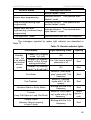
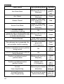
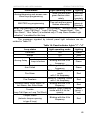
Table 7: Relay executive programs
1
Program name
‘On’
2
‘Off’
3
‘On for a time’
Number
26
Program description
If ‘Intrusion alarm’ or ‘Fire alarm’ then ON;
else OFF.
If ‘Intrusion alarm’ or ‘Fire alarm’ then OFF;
else ON output.
If ‘Intrusion alarm’ or ‘Fire alarm’ then ON for
a given time;
else OFF
INSTALLER’S AND USER’S MANUAL
Number
4
5
6
7
8
9
10
11
PRODUCT DESCRIPTION
Program name
‘Off for a time’
Program description
If ‘Intrusion alarm’ or ‘Fire alarm’ then OFF for
a given time;
else ON
‘Blinking. Normal
If ‘Intrusion alarm’ or ‘Fire alarm’ then blink
state OFF’
(0,5 s ON and 0,5 s OFF);
else OFF
‘Blinking. Normal
If ‘Intrusion alarm’ or ‘Fire alarm’ then blink
state ON’
(0,5 s ON and 0,5 s OFF);
else ON
‘Blinking for a time. If ‘Intrusion alarm’ or ‘Fire alarm’ then blink
Normal state OFF’ (0,5 s ON and 0,5 s OFF) during given time;
else OFF
‘Blinking for a time. If ‘Intrusion alarm’ or ‘Fire alarm’ then blink
Normal state ON’ (0,5 s ON and 0,5 s OFF) during given time;
else ON
‘LAMP’
If ‘Fire alarm’ then blink (0,25 s ON and 0,5 s
OFF)
If ‘Fire prealarm’ then blink (0,25 s ON and
0,75 s OFF)
If ‘Intrusion alarm’, ‘Entry alarm’ or ‘Arm failed’
then blink (0,5 s ON and 0,5 s OFF)
If “Fire trouble” then blink (0,25 s ON and 1,75
s OFF)
If there is at least one armed loop then ON
If all loops are disarmed then OFF
‘Alarm output 1’
If all relay assigned loops are armed then ON
(close output)
else OFF (open output)
‘ASPT’
If at least two relay assigned loops have entered the ‘Fire alarm’ status and there are no
broken auxiliary loops then ON for a given
time
The breaking of an auxiliary loop blocks
switching on
If the auxiliary loop has broken during the relay control delay then when recovering the
output will be turned ON for a given time (the
auxiliary loop breaking holds the turning on
delay counting)
Else OFF
27
S2000-4 INTRUSION&FIRE AND ACCEESS CONTROL PANEL
12
Program name
‘SIREN’
13
‘Fire output’
Number
‘Output FAULT’
14
‘Fire LAMP’
15
‘Alarm output 2’
16
28
17
‘Turn on for a given
time before arming’
18
‘Turn off for a given
time before arming’
19
‘Turn on for a given
time when arming’
20
‘Turn off for a given
time when arming’
Program description
If ‘Fire alarm’ then blink for a given time (1,5 s
ON and 0,5 s OFF)
if ‘Fire Prealarm’ then blink for a given time
(0,5 s ON and 1,5 s OFF)
if ‘Intrusion alarm’ then ON for a given time
else OFF
If ‘Fire alarm’ or ‘Fire prealarm’ then ON
(close output)
else OFF (open output)
If there are loops having the statuses “Fire
trouble”, “Disarmed” or “Arm failed” then
switches output OFF (opens)
else ON (closed output)
In case of ‘Fire alarm’ switches in interrupted
mode (0,25 s ON and 0,25 s OFF)
In case of ‘Fire prealarm’ switches in interrupted mode (0,25 s ON and 0,75 s OFF)
In cases of ‘Intrusion alarm’, ‘Entry alarm’ or
“Arm failed” switches in interrupted mode (0,5
s ON and 0,5 s OFF)
In case of ‘Fire trouble’ switches in interrupted
mode (0,25 s ON and 1,75 s OFF)
If all associated loops are armed switches
output ON
else OFF
If all associated loops are armed or disarmed
then turns output ON
else turns OFF
During arming delay period turns ON for a
given time
otherwise OFF
During arming delay period turns OFF for a
given time
otherwise ON
If at least one loop is armed switches the relay ON for a given time
else OFF
If at least one loop is armed switches the relay OFF for a given time
else ON
INSTALLER’S AND USER’S MANUAL
Number
21
22
23
24
25
26
27
28
29
30
31
32
33
PRODUCT DESCRIPTION
Program name
‘Turn on for a given
time when disarming’
‘Turn off for a given
time when disarming’
‘Turn on for a given
time if arming has
failed’
‘Turn off for a given
time if arming has
failed’
‘Turn on for a given
time when auxiliary
alarm’
‘Turn off for a given
time when auxiliary
alarm’
‘Turn on when disarmed’
Program description
If at least one loop is disarmed switches the
relay ON for a given time
else OFF
If at least one loop is disarmed switches the
relay OFF for a given time
else ON
If at least one loop is in the state ‘Arm has
failed’ switches the relay ON for a given time
else OFF
If at least one loop is in the state ‘Arm has
failed’ switches the relay OFF for a given time
else ON
If at least one loop is in the state ‘Auxiliary
alarm’ switches the relay ON for a given time
else OFF
If at least one loop is in the state ‘Auxiliary
alarm’ switches the relay OFF for a given time
else ON
Turn the relay ON if at least one assigned
alarm loop is disarmed
else OFF
‘Turn off when dis- Turn the relay OFF if at least one assigned
armed’
alarm loop is disarmed
else ON
‘Turn on when
Turn the relay ON if at least one assigned
armed’
alarm loop is armed
else OFF
‘Turn off when
Turn the relay OFF if at least one assigned
armed’
alarm loop is armed
else ON
‘Turn on when aux- In case of ‘Auxiliary alarm’ turns the relay ON
iliary alarm’
else OFF
‘Turn off when aux- In case of ‘Auxiliary alarm’ turns the relay
iliary alarm’
OFF
else ON
‘ASPT-1’
If the alarm loop has entered the ‘Fire alarm’
status and there are no broken auxiliary loops
then switches the relay ON for a given time
If an auxiliary loop has broken during the relay
29
S2000-4 INTRUSION&FIRE AND ACCEESS CONTROL PANEL
Program description
control delay then when recovering the output
will be turned ON for a given time (the auxiliary loop breaking holds the turning on delay
counting)
‘ASPT-A’
If at least two assigned alarm loops have entered the ‘Fire alarm’ status and there are no
broken auxiliary loops then switches the relay
ON for a given time
34
In case of broken auxiliary loop the switching
has blocked and the relay has remained OFF
even after loop recovering
‘ASPT-A1’
If there is alarm loop having ‘Fire alarm’ status
and there are no broken auxiliary loops then
switches the relay ON for a given time
35
In case of broken auxiliary loop the switching
has blocked and the relay has remained OFF
even after loop recovering
"Turn on with tem- If an alarm loop has entered “High temperaperature increasture” status*, that is, the temperature has exceeded "temperature high" threshold then
36 ing"
switches ON
else OFF
"Turn on with tem- If an alarm loop has entered “Low temperaperature decreas- ture” status*, that is, the temperature has exceeded "temperature low" threshold then
37 ing"
switches the relay ON
else OFF
Remark* Only programmable auxiliary alarm loop (type 12) can enter the
statuses “Temperature High” or “Temperature Low” and only if these
statuses were programmed for this loop
Number
1.6
Program name
Access control
The panel is intended to be used for door access control, with the entering to the access-controlled area being identifier-protected and exiting
being performed by pressing “EXIT” button.
The Touch Memory or Proximity card reader is mounted in front of
the door into the protected area, the “EXIT” button being placed indoors.
The “EXIT” button and door opening detector (if used) are included
into the first panel alarm loop in accordance with the connection diagram
30
INSTALLER’S AND USER’S MANUAL
PRODUCT DESCRIPTION
being contained to the appendix C. The parameter “Loop Type” has to be
selected as “Burglary” (type 4) or “Entering” (type 7).
The relay 1 in this case is used to control electromagnetic lock. To
control the electromechanical lock the executive program 3 is used (“On for
a time”), but for electromagnetic lock control it should select the program 4
(“Off for a time”). The parameter “Relay 1 Control Time” defines the maximum period of relay being turned on (off) when access providing. The relay
binding with loops and external control commands (apart from the access
control commands) are ignored.
If the presented identifier (Proximity card or Touch Memory keys) is
registered in the panel memory then the "S2000−4" panel resolves if the
access will be gained on base of key authority level, current access mode
and key access violation presence. This is the local control process.
If the presented identifier is not registered in the panel memory then it
will be transmitted to the net controller (ARM “Orion”) which has to come to
a decision about access granting or prohibiting. This centralized control is
possible if the panel operate as a part of the safety system controlled by
PC.
“Access” attributed keys being written into the “S2000-4” panel memory can be access limited by the following factors:
- date and time, if the time window for this key access is not active
(see 1.7 section);
- key validity period, if it has elapsed or has not yet begun;
- in "Access Closed" mode when access blocking alarm loops are
armed, or access is closed by RS-485 interfaced command or by special
Closing key (see section 1.6.2).
If the electromagnetic lock or latch being in use is connected to the
same power supply as the device then it should be supplied by separate
wire. It is recommended to supply the electromagnetic locks by separate
power source.
If the electromagnetic lock design is not provided with the scheme of suppression of high voltage pulse appearing during the commutation it is necessary
to connect the lock terminals in parallel with the reverse directed diode, with direct diode current available being no more than 1 А.
1.6.1
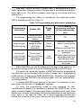
Access control configuration parameters
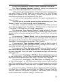
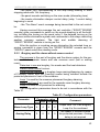
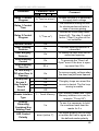
The configuration parameters dealing with the access control process
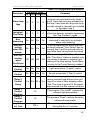
are shown in Table 8.
31
S2000-4 INTRUSION&FIRE AND ACCEESS CONTROL PANEL
Table 8: Access control configuration parameters
Parameter
Description
Range
Access Control
Door Opening
Detector
"Passed" Event
Door Burglary
Control
Door Blocking
control
Door Blocking
Time Out
Access control is in use
Door opening detector is
connected
To form the "Passed" event
To control the unauthorized
door openings
To control the time the door
having been opened
Available duration of the
door having been opened
Pre-schedule interrupt of
relay 1 opening program
when incomer have opened
the door
Pre-schedule interrupt of
relay 1 opening program
when incomer have closed
the door
On / Off
Default
value
Off
On / Off
Off
On / Off
Off
On / Off
Off
On / Off
On
1 ... 255 s
30 s
On / Off
On
On / Off
Off
0…65535
(65535
means
zone
undefined)
65535
Turn Relay 1 Off
When Door
Is Opening
Turn Relay 1 Off
When Door
Is Closing
Access Zone
Number
To Deny Access if Any
Pointed Loop
Is Armed
loop1
To Deny Access if All
Pointed
Loops Are
Armed
loop1
loop2
loop3
loop4
The number of the access
zone with entering controlled by the panel (being
used as a part of the system)
The list of access denying
alarm loops any being
armed ("Or" denying)
The list of access denying
alarm loops all being armed
loop3
("And" denying)
loop4
loop2
On / Off
On / Off
On
On
On
Off
Off
Off
Off
Off
The parameter "Access Control" activates the access control functions of the panel. If this parameter is off the access control is not realized,
with the first loop being of any type and the first relay being controlled by
loops with the help of any programs local or centralized.
32
INSTALLER’S AND USER’S MANUAL
PRODUCT DESCRIPTION
Further let’s suppose the “Access Control” parameter to be set on.
The “Door Opening Detector” parameter setting on indicates the
usage of the door opening detector. In such a case:
- After access gaining the panel is waiting for the door opening (passing) within "Relay 1 Control Time", but no less then 10 s. Until the door
having been opened or until the "Relay 1 Control Time" expired the new
identifier presentation is not considered by the panel
- in case of door having been opened the panel can generate the
“Passed” event
- the door can be controlled against burglary and blocking (see "Door
Burglary Control" and "Door blocking control" parameters)
- the relay 1 control the lock can turn off before the "Relay 1 Control
Time" having expired (see "Turn Relay 1 Off When Door Is Opening" and
"Turn Relay 1 Off When Door Is Closing" parameters).
The parameter “Door Opening Detector” being turned off, the mentioned functions are enabled, the passing is not waited and reader LED indicates the fact of access gaining during “Relay 1 control Time” but no less
than 2 s.
If the parameter ““Passed” Event” is set on then during door opening
after access gaining the panel generate the message about the passing.
This report can be needed for “Net Anti-Passback” function or “Time-andAttendance” recording when using under “Orion” system.
If the parameter "Door burglary control" is set on then in case of
door opening without access gaining the alarm message “Door Forced” is
generated and light and sound signaling goes off.
If the parameter "Door blocking control" is set on then in case of
door being opening within period exceeding the “Door Blocking Time Out”
the alarm message “Door Left Open” is generated and light and sound signaling goes off.
The parameter “Turn Relay 1 Off When Door Is Opening” being set
on, the turning relay 1 on (off) when access gaining interrupts just after the
door having been opened before the “Relay 1 Control Time” elapsing.
The parameter “Turn Relay 1 Off When Door Is Closing” being set
on, the turning relay 1 on (off) interrupts just after incomer has closed the
door. This parameter used to be set in case of electromagnetic lock being
controlled with the help of executive relay 1 program "Выключить на время".
If one of “Turn Relay 1 Off When Door Is Opening” and “Turn Relay 1
Off When Door Is Closing” is set on then the “Relay 1 Control Time” defines the maximum time period for passing. The actually time of turning
on(off) shall be less or equal to “Relay 1 Control Time”.
33
S2000-4 INTRUSION&FIRE AND ACCEESS CONTROL PANEL
“Access Zone number" is important in case of the system “Orion”
operation mode важен when using Anti-Passback or Time-and-Attendance
functions. It is the number of access zone in the system the panel to gain
access when identifier reading. This number is displayed by the panel in
connection with the passing event and access gaining/denying. If the panel
is used as a part of the system but Anti-Passback or Time-and-Attendance
functions are not in use it should retain the default value of this parameter
being equal to 65535. Passing events with such of access zone number
are not retranslated to the other devices.
Local access by means of “S2000-4” panel recorded the panel are
armed.
If the access blocking is required in case of arming any from the
pointed loops one must include these loops to the list of “To Deny Access
if Any Pointed Loop Is Armed” parameter.
If the access blocking is required in case of only all pointed loops
arming one must include these loops to the list of “To Deny Access if All
Pointed Loop Are Armed” parameter.
1.6.2
Access modes
The panel can have one access mode from three available ones:
- "Normal"
- "Access closed"
- "Access opened"
In “Normal” access mode the access is gained for such identifiers
(keys) which are recorded to the panel database, have the “Access” attribute, are not blocked, have no expired key validity period and have no time
zone offences.
The panel enters the “Access closed” mode in such a case:
- arming of the loops blocking access
- special Closing key presenting
- net controller command via RS-485 interface.
If the access is closed by Closing key or command then reader LED
enters the interrupted red light mode with the 1 Hz frequency and short
pauses. In such a case the access is closed for all panel recorded keys.
It the access is closed by reason of blocking access loops being
armed then in case of combined key having disarming this loops privileges
presenting the loops are disarmed and access is gained simultaneously.
For other keys either for access only or combined without blocking loops
disarming privileges the access is prohibited.
Access closing because of loops is removed by means of blocking
loops disarming.
34
INSTALLER’S AND USER’S MANUAL
PRODUCT DESCRIPTION
If the access has closed by Closing key or RS-485 interfaced command then “Normal” mode recovering is realized either by repeated presenting of Closing key or by Opening key presenting or by net controller
command via RS−485 interface.
The “Access Opened” mode entering is realized by Opening key presenting or by net controller command via RS−485 interface. It is accompanied by reader LED green interrupted lighting with the 1 Hz frequency and
short pauses. In this mode the access is free and any identifier presenting
is not required.
In “Access Opened” mode the corresponding relay is given by the
panel opening action permanently so that the relay is continuously turned
on (off). Therefore this mode must not be used for several type devices
that cannot be powered all time.
The “Normal” access mode recovering is realized either by repeated
presenting of Opening key or Closing key presenting or by net controller
command via RS−485 interface.
1.7
Double identification
The panel reader can realize the specific operational mode when to
identify the person it is necessary to present two identifiers instead of one,
e.g., Proximity card followed by PIN code. Such a mode is called as double
identification and to enter it the "Double Identification" parameter shall be
set.
If the parameter “Double Identification” is set, this mode will be used
not only for access and arming/disarming keys but for special keys
(MASTER, Opening, Closing).
The double identification procedure begins with the presenting of the
first identifier or "Main Code". If this key is recognized the panel enters to
the mode of waiting for the second identifier, or "Extra Code", and the
reader light indicator blinks with green color and 5 Hz frequency. For half a
minute it is necessary to present the extra identifier.
If the second identifier presented is not coincided with extra code
then the message "Illegal Code" with the "Extra Code Error" attribute is
generated.
If the extra code presented is correct then the identification procedure
is considered as successful and the panel executes such action the presented key is assigned to (access gaining, alarm arming/disarming, key
programming mode entering or access opening or closing.
If the identification procedure needs to be simplified for some keys
when all other keys have to be double identified one can set "Without Extra
Code" for given keys. To identify with the help of such keys it is enough to
present only main key without extra one.
35
S2000-4 INTRUSION&FIRE AND ACCEESS CONTROL PANEL
Since in case of double identification the panel is to store two codes
for each user (main and extra) then the maximum “S2000-4” panel storage
capacity is only up to 1024 codes.
Main and extra codes are presented to the same reader so the combining of different code types, for example Proximity card + PIN-code, is
possible only in case of using of integrated devices providing different type
identifier reading and transmitting to the panel using unified format (Touch
Memory, Wiegand or ABA TRACK II).
1.8
Time windows
The panel time windows are used to:
- limit the access into the protected premises depending on date,
weekday and time of day;
- limit the assigned arming/disarming authority depending on date,
weekday and time of day;
- arm and disarm alarm loops automatically at the given time.
To add the access time restrictions each key is assigned with the
number of access time window. To restrict arming/disarming authorities the
key is assigned with the number of arming/disarming time window.
The assigning with “0” number time window means the absence of
date, time or weekday limitations. Time window parameters with the numbers from 1 to 16 are programmed by the panel.
The time window descriptor consists from the list of 10 time intervals
and the list of red-letter days for one year.
The time interval description comprises the beginning hours and minutes, the finishing hours and minutes and activity attribute for all weekdays
and red-letter days.
The red-letter day list allows to redefine the weekday for a year or to
declare any day as red-letter. If the day is not redefined in the red-letter
day list (black-letter day) than this weekday corresponds to the calendar
day. If the day is redefined the calendar is ignored and the panel consider
this day in accordance with the red-letter day list. Redefined weekday can
take the following values: 1 (Monday), 2 (Tuesday),
7 (Sunday), 8
(Eighth Timetable Day), 14 (Fourteenth Timetable Day), “Red-letter Day”.
The last value “Red-letter Day” is designed to simplify the comprehension
of the list and is not distinct from the other values. It can be called as the
“Fifteenth Timetable Day”.
So the red-letter day list allows to:
− Declare any day as red-letter day, that is the day with time intervals
unlike intervals given for other weekdays are active
36
INSTALLER’S AND USER’S MANUAL
PRODUCT DESCRIPTION
− Set weekdays aside (e.g., Saturday can be redefined as Monday
− Program complex sliding access timetables with the period less or
more than 7 days
− Program complex access timetables without return period.
One can mention two typical ways of creating the red-letter list.
The first way. If the employer access timetable (or working timetable)
is assigned with the calendar week (for example, the days from Monday to
Friday are black-letter and the Saturday and Sunday are red-letter days)
then the most og days are not redefined. Some days are marked as “Redletter Day”, or redefined in case of setting aside, or redefined to values
more than 7 if the special access time intervals are to be in use in such a
days.
The second way. One can create the complex and sliding access
timetables (or working timetables) not attached to the calendar week. In
such a case all days in the list are given by “weekday” directly (are redirected).
To restrict the access or to arm/disarm depending on the date and
the time or key validity period the internal panel clocks have to be synchronized. It is supplied automatically when the panel operates as a part of
safety system “Orion” based on PC or “S2000M”/”S2000”ver.1.20 or above.
In stand-alone panel operation mode the access and arming/disarming
time restrictions or scheduled arming/disarming are out of use.
If the parameters “Scheduled Arming” and “Scheduled Disarming” are
set for any alarm loop then in the moment when the “Arming/
Disarming Time Window” time interval (see Table 17) has been active the
loop is disarming. But in the moment when this time interval has been over
the loop is attempted to arm. Scheduled arming and disarming doesn’t disable other ways of alarm loop arming and disarming.
1.9
Centralized access and partition control
If the panel operates as a part of security system "Orion" it can work
with identifiers registered by net controller (with the proper privileges) but
not recorded to the panel database. Such identifiers can be used for centralized control only if the system is controlled by "ARM Orion". And they
can be used for partition arming/disarming if the system is controlled by
"ARM Orion" or "S2000"/"S2000M" console.
Like local the centralized keys can be combined for access gaining
and arming/disarming both. More over the local access gaining can be integrated with the centralized partition control for keys being recorded to the
panel database with the "Access" attribute.
37
S2000-4 INTRUSION&FIRE AND ACCEESS CONTROL PANEL
If unknown identifier is presented to the panel connected reader its
code is transmitted to the computer or console. The reader light indicator is
switching from red to green alternately with the 5 Hz frequency until the
computer or console response has been received. It can takes from a fraction up to a few seconds depending on the number of devices being connected to the RS-485 interface.
If the net controller decides to gain the access the centralized access
is available along with the local one.
If the key presented is assigned with the partition control privileges
then the reader LED displays the current partition status accordingly to the
Table 9. The second presenting of this key leads to arming of disarmed
partition or to disarming at any other case. Each subsequent identifier presenting causes the action contrary to preceding one, that is, if the second
presenting has resulted in partition disarming then the third presenting results in partition arming. If the key privileges are limited, for example, only
arming is permitted then the repeated and all followed presenting results in
only allowed operation (arming in this case) regardless of the current partition status.
Table 9: Partition status representation
Partition status
Reader LED mode
Light color
"Disarmed"
Turned off
-
"Armed"
Turned on
Yellow
(green + red)
"Alarm", "Fire Alarm", "Fire
Blinks with 2 Hz frequency
Prealarm", "Arm Failed"
"Fire Trouble"
Short flashes with 1 s
regularity
(in fire partition)
Yellow
Yellow
If the identifier presented is not recognized by the net controller or it
has not access authority then the panel indicates the access denying, that
is, the panel and reader sounders makes the long audible signal "Error",
but reader LED blinks three times and then is red lit continuously.
If when presenting the unknown key the panel is not communicated
with the computer then the message "Illegal Code" is generated. This message along with the other ones is storied into the panel non-volatile memory and is to be transmitted to the computer when the communication has
been recovered.
If the combined key (for centralized access and partition control or for
local access and partition control) is presented then the access is gained.
38
INSTALLER’S AND USER’S MANUAL
PRODUCT DESCRIPTION
To control the partition by means of this key it is necessary previously to
switch the panel mode to the “Arming/Disarming Readiness” mode identically to the loop arming/disarming local control combined keys using (see
section 1.4.2.
The communication between the panel and the net controller being
absent, the centralized access and partition control are impossible.
When centralizes access and partition control are in use the double
identification is not supported.
1.10 Reader connection
To read off the identifier codes it is necessary to connect the reader
with Touch Memory, Wiegand or ABA TRACK II (magnetic card) interfaces
to the panel. One can use any identifier such as Touch Memory keys, Proximity labels, cards or tags, magnetic cards, PIN-codes and so on designed
for readers transmitting the identifier code to the panel in one of the mentioned above interface formats. The panel terminals designation can be
shown in the Table 10.
Table 10: “S2000-4” terminals designation for reader connection
Terminal
D0
D1
Input or output
Designation
Input/Output
Reader data
Input
Reader "D0" data
Input
Reader "DATA" data
Touch Memory
mode
-
Is not in use
Wiegand mode
Input
Reader "D1" data
ABA TRACK II
mode
Input
Reader "CLOCK" tick
LEDG
Output
Reader green LED controller
LEDR
Output
Reader red LED controller
BEEP
Output
Reader sounder controller
Touch Memory
mode
Wiegand mode
ABA TRACK II
mode
The reader is connected by coupling the terminals listed above with
the reader contacts of the same name. The readers having the useful current above 100 мА or being located far from the panel (50 m or farther)
then to supply them one must use the separate wire pair connected to the
power supply directly.
39
S2000-4 INTRUSION&FIRE AND ACCEESS CONTROL PANEL
If the reader is supplied separately the "GND" terminal (minus of
reader power) must be connected to the "GND" contact of "S2000−4".
The reader having sole unicolored LED, it control circuit is connected
to the "LEDG" contact of the panel in case of reader being used only for
access control. If the reader is used for loop arming/disarming only and access control is not in use then the unicolored LED control circuit has to be
connected to the "LEDR" contact of the panel “S2000-4”.
The reader having not sounder control input or sounder is not required then the "BEEP" contact of the "S2000-4" retains nonworking.
Some reader connection examples can be referred to at the Appendix E.
The reader configuration parameters are presented in Table 11.
Table 11: Reader configuration parameters
Parameter
Description
Range
Reader interface
type
The way of transmitting
of the read identifier
code to the panel
1 - Touch Memory
2 – Wiegand
3 - ABA TRACK II
Arming/
Disarming
Combined Key
Holding Time
Double
Identification
LED Control
Polarity
40
The time of holding the
combined key (card)
near the reader for loop
arming/disarming (only
for Touch Memory interfaced readers)
Two identifiers are presented for recognition
The active logic level
choice for reader LED
lighting
Default
value
1
(Touch
Memory)
0…32 s
0
(Off)
On / Off
Off
Direct
(active “1")
/ reverse
(active "0")
Direct
(active
“1")
INSTALLER’S AND USER’S MANUAL
Parameter
Reader LED
Standby Mode
1
Loop Arming
Reader Light
Indication
2
3
4
Loop Alarm
Reader Light
Indication
1
2
3
4
PRODUCT DESCRIPTION
Description
Range
Default
value
Describe the reader
LED lighting in standby
mode
1 - Off
2 - if any given
loop is armed
then LED is
red lit, otherwise is off
3 - if all given
loops are armed
then LED is red
lit, otherwise is
off
4 – red lighting
2
On / Off
On
On / Off
On
On / Off
On
On / Off
Off
On / Off
On / Off
On / Off
On / Off
Direct
(active “1")
reverse
(active "0")
On
On
On
On
The list of alarm loops
which arming results in
red reader LED turning
on (for 2 and 3 “Reader
LED Standby Mode”
The list of alarm loops
which breaking is indicated by reader LED
Sound Control
Polarity
The active logic level
choice for reader
sounders going off
Reader Access
Sound Alarms
Indication Programming
Reader sound signaling
of access gaining/denying, alarms and
entering into the programming mode
Direct
(active
“1")
On / Off
On
On / Off
On
On / Off
On
The “Reader Interface Type” (Touch Memory, Wiegand or ABA
TRACK II) parameter has to agree with the interface of the readers being in
use.
The Touch Memory interfaced reader being used, the “Arming/Disarming Combined Key Holding Time” parameter allows to control
loop arming and disarming with the help of combined key without previously panel switching to the “Arming/Disarming Readiness” mode. To
arm/disarm the loop one shall hold the key near the reader for this time. To
41
S2000-4 INTRUSION&FIRE AND ACCEESS CONTROL PANEL
gain the access one shall present the combined key to the reader for short
time, actual relay being switched on in the moment of removing the key
from the reader.
By default when the “S2000-4” panel has just been delivered the
“Arming/Disarming Combined Key Holding Time” parameter is set to zero
so that such a way of loop arming/disarming is off, with combined card access being gained instantly when the key is presented not when removed.
The “Double Identification” parameter setting means that to recognize
the same person it is necessary to present two identifiers instead of one
(see the section 1.7).
The “LED Control Polarity” parameter defines the active logic level for
reader red and green LED control. If the direct polarity is given then the
LED switching on is realized by logical “1” level issue to the “LEDG” and
“LEDR” contacts of the panel. If the reverse control polarity is given then
the LED switching on is realized by logical “0” level issue.
In standby mode the reader LED can be either always turned off, or
turned on (with the red lighting), or indicates the certain alarm loops being
armed (the LED is lit) or disarmed (the LED is not lit). It is defined by
“Reader LED Standby Mode” parameter and the list of alarm loops which
“Loop Arming Reader Light Indication” parameter is on.
The “Loop Alarming Reader Light Indication” parameter defines the
list of loops which breaking are indicated by reader LED.
The “Sound Control Polarity” parameter defines the active logic level
for reader sounder control similarly to the LED control polarity.
The reader sound indication parameters allow sounder going off for
each signal categories (see section 1.11).
1.11 Light and sound signaling
The panel uses the internal light indicators (LED) and internal
sounder along with light and sound reader indicators to communicate system information to you.
The messages signaled by panel “READY” light indicator are described in Table 12.
Table 12: Panel “READY” indicator lights
Event or status
Message description
Operating mode
Light indicator is on
Power supply trouble (supply
voltage is out of range)
Indicator blinks with the 2 Hz frequency
MASTER key programming
Indicator blinks in "Time spaced short
42
INSTALLER’S AND USER’S MANUAL
PRODUCT DESCRIPTION
Event or status
Message description
double flashes" mode
Access keys programming
Indicator blinks in " Time spaced short
flashes" mode
Loop arming/disarming keys
programming
Indicator blinks in "Time spaced short
double flashes" mode
Access keys and arming/disarming (combined) keys
programming
Indicator blinks in " Time spaced short
triple flashes " mode
“Test operation” mode
Indicator blinks with the 5 Hz frequency
The messages signaled by reader light indicator are described in
Table 13.
Table 13: Reader indicator lights
Panel status
" Reader LED standby
Standby
mode " is 1 (off)
mode, that
"Reader LED standby
is, no alarms
mode" is 2 or 3 (loop
and normal
arming indication)
access
"Reader LED standby
mode
mode " is 4 (red light)
Fire Alarm
Fire Prealarm
Intrusion Alarm or Entry Alarm
Light operating mode
Lighting
Off
-
On if the loop is armed
otherwise is off
Red
On
Red
Blinks in "Short stopping" mode with 1 Hz
frequency
Blinks in "Flashing"
mode with 1 Hz frequency
Blinking with the 2 Hz
frequency
Red
Red
Red
Trouble
(Loop Trbl Open or Loop Trbl Short)
Blinks in "Short flashing" mode with o,5 Hz
frequency "
Yellow
(green +
red)
Tamper Alarm
(detector tamper opening
in type 5 loop)
Blinking with the 2 Hz
frequency
Red
43
S2000-4 INTRUSION&FIRE AND ACCEESS CONTROL PANEL
Panel status
Light operating mode
Lighting
Aux Zone Alarm
Blinking with the 2 Hz
frequency
Yellow
(green +
red)
Arm Failed
Access Closed
Access Free Mode
Access Granted,
the passing is waiting
The extra code is waiting (after main
code having been presented in case
of double identification)
Access Denied
The unknown key is presented, the
net controller verdict is waiting
Blinking with the 2 Hz
frequency
Blinks in "Short stopping" mode with 1 Hz
frequency
Blinks in "Short stopping" mode with 1 Hz
frequency
Green
Red
Green
On
Green
Blinking with the 5 Hz
frequency
Green
Three flashes blinking
with the 3 Hz frequency
Switches from red to
green with
5 Hz frequency
Red
Red/
Green
Partition centralized control, partition
being armed
On
Yellow
(red +
green)
Partition centralized control, partition
being disarmed
Off
-
Partition centralized control,
partition alarm
Blinking with the 2 Hz
frequency
Partition centralized control,
partition trouble
Flashes with
1 Гц frequency
Access
keys programming
Red and green flashes
alternately
Arming/Disarming
Keys Programming
Two red and two green
flashes alternately
44
Yellow
(red +
green)
Yellow
(red +
green)
Red and
green alternately
Red and
green alternately
INSTALLER’S AND USER’S MANUAL
PRODUCT DESCRIPTION
Panel status
Light operating mode
Lighting
Red and
green alternately
Red and
Two red and two green
MASTER key programming
green alflashes alternately
ternately
Note: loop alarming ("Fire Alarm", "Fire Prealarm", "Intrusion Alarm", "Entry Alarm", "Loop Trbl Short", "Loop Trbl Open", "Tamper Alarm", "Aux
Zone Alarm", "Arm Failed") is indicated only if "Loop Alarm Reader Light
Indication" is enabled for this loop
Arming/disarming and access combined keys programming
Three red and three
green flashes alternately
The messages signaled by internal panel light indicators are described in Table 14.
Table 14: Panel indicator lights "1" - "4"
Loop status
Disarmed
Armed
Loop is normal
Arming Delay
Loop is broken
Light operating mode
On
On
On
Blinking with the 2 Hz
frequency
Blinking with the 2 Hz
Arm Failed
frequency
Blinks in "Short stopping"
Fire Alarm
mode
with 1 Hz frequency
Blinks in "Flashing" mode
Fire Prealarm
with 1 Hz frequency
Intrusion Alarm, Entry Alarm, SiBlinking with the 2 Hz
lent Alarm, Aux Zone Alarm
frequency
Blinks in "Short Flashing"
Trouble
mode with 0,5 Hz fre(Loop Trbl Open or Loop Trbl Short)
quency
Tamper Alarm
Blinking with the 4 Hz
(detector tamper opening
frequency
in type 5 loop)
Lighting
Green
Red
Green
Green
Green
Red
Red
Red
Yellow
(green +
red)
Red
45
S2000-4 INTRUSION&FIRE AND ACCEESS CONTROL PANEL
Loop status
Key programming
Light operating mode
The key doesn’t
Off
control the loop
The key has only Blinks in "Flashing" mode
arming authority
with 1 Hz frequency
The key has only Blinks in "Flashing" mode
disarming authority
with 1 Hz frequency
The key has
Red and green flashes
arming and disarmalternately
ing authority both
Lighting
Red
Green
Red/
Green
The messages signaled by reader and panel sounders are identical
and are described in Table 15.
Table 15: Panel and reader sounds
Status or event
Standby mode
Access is gained
Access is denied
The main code is presented in case of double identification
Category
Access
Access
Description
Turned off
Two short sounds
Long signal ("Error")
Access
One short signal
Access opening
by special key
Access
Access closing
by special key
Access
The recovering of access normal mode
by special key
Access
Fire
Alarm
46
The sequence from short, two
short and another two short signals ("Access Opened")
Long signal followed by four short
signals ("Access Closed")
The sequence from two short, another two short and one more short
signals
("Access Free Mode")
The panel sounder operates in alternating tone mode (siren)
The reader sounder operates in
continuous mode with short
pauses
INSTALLER’S AND USER’S MANUAL
Status or event
Category
Fire Prealarm
Alarm
Intrusion Alarm
Alarm
Entry Alarm
Alarm
Trouble (fire loop short
or open failures)
Tamper Alarm
(tamper breaking in
5 type loop)
Door Forced
Door Left Open (The
door has been opening
more than “Door
Blocking Time Out”
Entering to the key
programming mode
Exiting from the key
programming mode
Entering to the
MASTER key
programming mode
MASTER key has been
programmed
Adding of new key or
changing parameters of
the existing key, the
panel being in the key
programming mode
Presenting of the existent key in the key programming mode
Alarm
PRODUCT DESCRIPTION
Description
The panel sounder operates in the
paused alternating tone mode
(paused siren)
The reader sounder operates in
interrupted mode with
2 seconds period
Sounder operates in interrupted
mode with 1 seconds period
Sounder operates in interrupted
mode with 0,25 seconds period
Short sounds with
2 seconds period
Alarm
Sounder operates in interrupted
mode with 0,125 seconds period с
Alarm
Sounder operates in interrupted
mode with 0,25 seconds period
until the door having been closed
Alarm
Four short signals being repeated
with some seconds period
Programming
Programming
Three pairs of short sounds ("Programming")
Three short and long sounds
("Programming Finishing")
Programming
The "MASTER Programming"
melody
Programming
The end of "MASTER
programming" melody
Programming
Two short signals ("Key Recording
Confirmation")
Programming
Short sound ("The key has been
already recorded")
47
S2000-4 INTRUSION&FIRE AND ACCEESS CONTROL PANEL
Any signal category can be disabled for both panel and reader
sounder.
1.12 Configuration parameters
Following are the seven configuration parameter groups:
- system configuration parameters;
- loop parameters (see Table 4);
- relay parameters (see Table 6);
- access control parameters (see Table 8);
- reader configuration parameters (see Table 11);
- time window parameters (see the section 1.7);
- identifier configuration parameters (see Table 17).
System configuration parameters are shown in Table 16. Other configuration parameters are considered at the corresponding sections.
Table 16: System configuration parameters
Parameter
Net address
MASTER
Programming
Inhibit
PIN-code max
length
Panel
Sound
Indication
Access
Alarm
Programming
Description
RS-485 interface
net address
The main MASTER key
generation by means of the
panel tamper detector
is inhibited
The maximum number of
PIN-code digits for readers
with Wiegand interface
transmitting the PIN-code
to the panel one digit after
one
Звуковая сигнализация в
приборе о предоставлении/запрете доступа, тревогах и включении режима
программирования ключей
Range
Default
value
1…127
127
On / Off
Off
1…12
6
On / Off
On
On / Off
On
On / Off
On
”Net address” parameter is used for RS-485 communications. When
having been connected to the “Orion” safety system the panel has to be
assigned with net address.
48
INSTALLER’S AND USER’S MANUAL
PRODUCT DESCRIPTION
The " MASTER Programming Inhibit" parameter turning on inhibits
the procedure of programming the main MASTER key with the help of the
panel tamper. In such a case the panel key recording is possible only from
the computer or by means of previously generated MASTER keys.
If the Wiegand interfaced keypad transmitting the PIN-code to the
panel one digit after one is used as a reader then the code entering is considered as completed when the number of digits entered has reached the
“PIN-code max length” parameter. To complete the less codes entering
press "#" button (code 0B hex) on the keypad.
All available panel sounds are divided into three categories such as
"Access", "Alarm" and "Programming" (see Table 15). The internal
panel sounder going off is defined by the corresponding parameters status.
To change the configuration parameters use the "uprog.exe" program versions 4.0.0.810 or above.
ATTENTION! Don’t use the earlier versions of "uprog.exe" program
or “S2000”/”S2000M” console for changing of the configuration parameters.
The program "uprog.exe" runs under Windows-98 or above operational
systems. To connect the panel to the COM-port use the interface converter
such as “PI-GR”, “S2000-PI”, “S2000” console version 1.20 or above or
“S2000M” console. The latest version of device configuring program
"uprog.exe" along with the related information is available at the
www.bolid.ru.
1.13 Identifiers
Identifiers such as Touch Memory keys, Proximity cards or PINcodes can be used along with the "S2000-4" panel with the aim of:
- access gaining;
- alarm loop arming/disarming;
- partition arming/disarming;
- access opening and closing;
- other identifiers programming (recording into the panel memory).
The identifiers have to be recorded into the "S2000-4" panel memory
except for identifiers used for partition control or centralized access which
are recorded only into the net controller database.
1.13.1 Identifier parameters
Up to 2048 identifiers can be entered to the panel database. They
can be Touch Memory keys, or Proximity cards, or PIN-codes. Each identifier has the parameter set (attributes), demonstrated by Table 17.
49
S2000-4 INTRUSION&FIRE AND ACCEESS CONTROL PANEL
Table 17: Identifier attributes
Attribute
Description
Key type
Defines the key destination
Blocking
The key is disabled (doesn’t effects)
To identify this key the extra code is
not obligatory, double identification for
other keys being required for other
keys (see section 1.7)
Loop arming/disarming designated key
Without Extra
Code
User key
Loop 1 Arming
Loop 2 Arming The list of alarm loops which are available for arming by this key
Loop 3 Arming
Loop 4 Arming
Loop 1
Disarming
Loop 2
Disarming
The list of alarm loops which are available for arming by this key
Loop 3
Disarming
Loop 4
Disarming
Arming/
The time window when arming and disDisarming Time
arming are permissible
Window
The key is designed for access
Access
Access Time
The time window when
access is permissible
Window
Validity
Defines is there restrictions of key validity period or not
Restriction
Key Validity
Period
The start and finish
dates of the key validity
Range
Basic
MASTER
Opening
Closing
On / Off
On / Off
On / Off
On / Off
On / Off
On / Off
On / Off
On / Off
On / Off
On / Off
On / Off
0 ... 16
On / Off
0 ... 16
On / Off
01.01.2000 …
… 31.12.2255
The “Key Type” parameter defines the main designation of the given
key.
50
INSTALLER’S AND USER’S MANUAL
PRODUCT DESCRIPTION
Basic key is designed for access or loop arming/disarming.
MASTER key is designed for programming (or adding) of the new
keys. The keys programmed with the help of MASTER key have Basic
type.
Opening key is designed for access opening (access free mode) and
normal access mode recovering (see 1.6.2).
Closing key is designed for access closing and normal access mode
recovering (see 1.6.2).
The “Blocking” parameter setting on defines any type key prohibition.
It is used for temporary key blocking (for example, in case of key loss) the
recovery possibility being retained.
The “Without Extra Code” parameter simplifies several key identification in case of double identification using (see 1.7). If double identification
is not realized this key parameter is ignored.
If the parameter “User Code” is set the key is used for loop arming
and disarming. The parameters “Loop1 Arming” – “Loop4 Arming” and
“Loop1 Disarming”-“Loop4 Disarming” gives the lists for arming and disarming accordingly.
The "Arming/Disarming Time Window" is the number of time window defining the time periods when loop arming and disarming are enabled. If it is equal to zero then arming and disarming are enabled at any
time.
If the “Access” parameter is set the key is used for access control.
"Access Time Window" is the number of time window defining intervals for access gaining. If this parameter is set to zero the access is free at
any time.
If the parameter “Validity Restriction“ is set then the beginning and
finishing time are given by “Key Validity Period” parameters. Otherwise
the key has unrestrictive validity period. This parameter can be attributed to
any type of key.
1.13.2 Identifier programming
The panel operating as a part of the “Orion” safety system based on
PC, the Touch Memory, Proximity card, PIN-code or other identifier are entered into the panel non-volatile memory by means of ARM Orion Database
Administrator software.
51
S2000-4 INTRUSION&FIRE AND ACCEESS CONTROL PANEL
If the panel is operated in stand-alone mode or as a part of the
“Orion” safety system controlled by “S2000” or “S2000M” console then the
identifiers are entered (programmed) by means of "uprog.exe" program
which is designed to add/delete keys, set or change their attributes, stores
keys into a file, load key list from the file into the panel and so on.
In addition one can program the keys without PC by means of one or
more so-called MASTER-keys. Any identifier given by MASTER type key
attribute can be MASTER-key. The presenting of MASTER key turns on
the key programming mode. In this mode all other presented keys are recorded to the panel memory with the type Basic and take over all
MASTER-key parameters such as “Access”, “User Code”, “Loop Arming/Disarming List”, “Access Time Window”, “Arming/Disarming Time Window” and “Key Validity Period”.
One MASTER-key can be programmed by panel itself without PC. To
do this it is necessary to open the panel cover and gradually realize one
long (more than 1,5 s), one short (less then 0,5 s) and one more long tamper pressing. The pauses between pressings must not exceed 0,5 s.
In such a case the panel and reader sounders make the “MASTER
programming” melody. The Ready LED of the panel and reader LED synchronously blinks by twice flashes, with reader LED flushing twice by red
and twice by green.
After that it is necessary within 30 s to present the identifier to be
programmed. The panel and reader sounders will make the end of the
“MASTER programming” melody, with the Ready LED and reader LED enter the continual mode.
Attention! The MASTER key programming with the help of tamper removes all keys having been recorded by the panel before. The
MASTER key programming by means of "uprog.exe" program does not
affect upon the keys programmed earlier.
If the programming key mode is entered with the help of MAIN
MASTER key then the programmed key status can be changed by means
of tamper. Long (more than 1,5 s) tamper pressing switches the “Access”
and “User Code” attributes of the programming keys successively between
the “only access”, “only arming/disarming” and “Access and arming/disarming” (combined) values.
When the “User Code” attribute is set for the programmed key then
tamper short pressing series changes the key loop arming/disarming privileges by successively switching between “arming and disarming”, “only
arming” and “does not control this loop” values.
52
INSTALLER’S AND USER’S MANUAL
PRODUCT DESCRIPTION
One short tamper pressing changes loop 1 arming/disarming privileges, twice short tamper pressing changes loop 2 arming/disarming privileges and so on. The pauses between pressings in one series must not
exceed 0,5 s.
The programming key status is indicated by the panel and reader
LED in accordance with the Table 18.
Table 18: Programming key parameters displaying
Programming
key status
Reader LED
Ready
LED
1 ... 4 LED (display 1…4
loop arming privileges
of the programming
key)
Access key
Single red and
green alternately
flashes
Single
flashes
Off
Loop Arming/
Disarming key
Two green
flashes and two
red flushes
alternately
Twice
flashes
Access and
Loop Arming/
Disarming key
(combined)
Three green
flashes and three
red flushes
alternately
Trial
flushes
Turned off if the key
doesn’t control given
loop
Blinks by red when the
key has only arming
privileges
Blinks by green and red
alternately when the
key has given loop
arming and disarming
privileges
MAIN MASTER key can be added with the help of the computer. To
do this the first key in the list must be attributed with the MASTER type.
The panel can record any number of MASTER keys but programming
key attributes can be changed with the help of tamper only if programming
mode entering is realized by MAIN MASTER key. Otherwise the programming keys succeed MASTER key attributes apart from key type and without editing feature.
If several MASTER keys assume to be used it is necessary to program them with the help of "uprog.exe" program.
To enter the programming mode of keys designed for arming/disarming or access it is necessary to present the MASTER key to the
panel connected reader. The panel and reader sounders would make three
double short sounds, with reader LED lighting alternately by red and green
once, twice or trial (see the Table 18). In such mode the identifier presented are recorded to the panel memory with the MASTER key parame53
S2000-4 INTRUSION&FIRE AND ACCEESS CONTROL PANEL
ters. If the MAIN MASTER key was used then the programming key parameters can be changed with the help of tamper.
If the MAIN MASTER key was used the programming key parameters
can be edited by means of tamper. Twice short sound and 2 second longed
reader LED green lighting when the identifier is presented mean that the
new code has been entered to the panel or current key parameters have
been changed. Single short sound and 1 second longed reader LED green
lighting mean that such key with given parameters has already exist. The
long sound and trial red blinking of reader LED mean the key entering failure (the memory is full).
If the panel uses double identification then after main code having
been received the panel prompts to enter (or to present) extra code, with
reader LED beginning to blink by green with 5 HZ frequency Гц. After that
within 30 s it is necessary to present key or code to be written as extra for
main one having been presented before.
To exit programming mode after adding and programming of the all
the necessary keys one must present the same MASTER key that has
switched the programming mode on. Moreover the key programming mode
finishes automatically in case of no key presenting and no tamper pressing
having occurred within 30 s. After programming mode exiting the panel and
reader sounders make three short and one long sounds (“Programming
Completed”), Ready LED lights in continuous mode and reader LED enters
the standby indication mode.
Programming the keys without using of the computer has the following restrictions:
- It is impossible to program Opening, Closing and subordinate
MASTER keys
- It is impossible to assign the key validity period to the programming key
- When double identification is in use it is impossible to program the
key with “without extra code” attribute
In case of key programming with the help of "uprog.exe" program
such restrictions are absent. Moreover any key can be removed or
blocked. In addition the possibility of key text comments entering and storing in the memory remarkably simplifies the key list editing process.
54
INSTALLER’S AND USER’S MANUAL
APPLICATION
2 APPLICATION
2.1
2.1.1
Preparation for use
Protective measures
There are no dangerous voltage circuits within the panel.
The mounting and maintaining of the panel shall be executed under
power–off conditions.
2.1.2
The panel mounting
The panel can be mounted to the wall, or above the suspended ceiling, or to other places on premises being protected from atmospheric fallouts, mechanical damages and unauthorized access.
The installation procedure is as follows:
a) attach the panel to the wall in any convenient place
b) install the reader in front of the door to the protected premises or
inside the premises if access control is not in use
c) if the access control is in use place the “EXIT” button inside the
premises
d) attach the connecting wires in accordance with the “S2000-4”
connecting diagram presented in Appendix B.
2.1.3
RS-485 interface wiring
To connect the panel with the net controller via RS-485 highway interface refer to the connecting diagram in appendix B and execute the following steps:
a) Connect the A and B lines of RS-485 highway interface to the "A"
and "B" terminals of “S2000-4” panel
b) Connect the panel circuit "0V" to the similar circuits of preceding
and following RS-485 connected devices (it is not obligatory if the devices
are connected to the same power supply)
c) Delete XT3 jumper connecting the terminal 620 Оhм resistance to
the interface circuit (except for the latest device). This jumper is located
near the "A" and the "B" terminals of the “S2000-4” panel.
When wiring the RS-485 interface it should connect the devices to
the chain. If it is necessary to make long RS-485 interface branch (longer
than 50 m), for example, to reduce the cable length, it is recommended to
use the interface repeater “S2000-PI”. One can use no more than 10 repeaters (no more than 10 interface branches) in one RS-485 interface
55
S2000-4 INTRUSION&FIRE AND ACCEESS CONTROL PANEL
segment. The number of in-series “S2000-PI” repeaters (the number of
segments) is not restricted.
2.1.4
Changing the panel default settings
In networking operation mode the panel has to be assigned with the
unique net address in the range from 1 to 127.
To assign the address connect the panel to the “S2000”/”S2000M”
console or to the computer, with other devices being disconnected from the
RS-485 interface. Being used the computer has to be connected with the
panel through the RS-232/RS-485 interface converter such as “S2000-PI”,
or “PI-GR”, or “S2000-USB”, or “S2000”/”S2000M” console.
Then change the default address of “S2000-4” panel by means of
“S2000”/”S2000M” console or uprog.exe program running from the computer.
To adjust the panel for the particular application and to gain full capability it is probably to change some configuration parameters with the
help of uprog.exe program versions 4.0.0.810 or above (see 1.12 section).
In case of usage the panel along with the access identifiers it is necessary to record corresponding Touch Memory keys, Proximity cards, PINcodes or other identifiers to the panel memory. For local access control,
arming and disarming the identifiers have to be recorded to the panel
memory in accordance with the 1.13.2 section of this manual, but for centralized access control, arming and disarming the identifiers have to be recorded into the net controller memory.
2.2
2.2.1
Typical application
Fire alarm system without access control at the small object
The purpose is light and sound alarming of fire at the small object.
Detectors in use are fire smoke detectors, fire heat detectors and fire
manual call points.
Devices under control are light and sound annunciators.
Panel control algorithm is actuated loop rearming by means of Touch
Memory key.
The configuration parameters have to be set in accordance with the
Table 19.
56
INSTALLER’S AND USER’S MANUAL
APPLICATION
Table 19: Configuration parameters
Parameter
Parameter value
loop1 loop2 loop3 loop4
Comment
The smoke detectors without additional
resistors are included into the loops 1
and 2. Heat detectors are included into
2
the loop 3 and manual call points (both
normally closed or opened) are included
to the alarm loop 4
To enter the “Fire Alarm” mode in case
0 of one fire detector actuation bypassing
the “Fire Prealarm” mode
All loops are always armed. The arming
command is used only for actuated
On
alarm loop rearming
If during rearming the alarm loop has
not been restored (“Arm Failed” has ocOn curred) then it will be automatically armed after loop having been recovered
The recovering of the "Armed" mode
after "Fire Alarm" status is possible only
Off by means of operator command (presenting of the loop arming Touch Memory key to the Touch Memory reader)
Alarm loop
type
2
2
3
Intrusion/
Fire Delay
0
0
0
Nondisarming
On
On
On
Auto Rearming
when Disarmed
On
On
On
Auto Rearming
when
Fire/Alarm
Off
Off
Off
On
On
On
On
Light annunciator (“Lamp”) control
On
On
On
On
Sound annunciator (“Siren”) control
Relay 1
Control
Relay 2
Control
Relay 2
Control
Delay
Relay 1
Control
Program
Relay 2
Control
Program
Relay 2 Control Time
60 s 60 s 60 s 0 s
The 60 s delay is given to the user to
rearm actuated loop without siren getting off in case of false detector actuation. The siren is gone off if the signal
was received fron the manual call point
15
The program "Fire LAMP" controls the
external light annunciator
12
The program "Siren" controls the external sound annunciator
120 s
The maximum time of siren going off
during the fire is 2 minutes
57
S2000-4 INTRUSION&FIRE AND ACCEESS CONTROL PANEL
Access
Control
Reader
Interface
Type
LED
Control
Polarity
Reader
LED
Standby
Mode
Off
1 – Touch Memory
direct (active "1")
3, that is
if all given loops are
armed than the indicator is red, otherwise is turned off
Reader LED loop 1
Loop Arm- loop 2
ing Indica- loop 3
tion
loop 4
Reader LED loop 1
loop 2
Loop
Alarming loop 3
Indication
loop 4
The reader LED repeats "Fire LAMP"
tactic
On
On
On
LED is lit if all 4 alarm loops are armed
On
On
On
On
Any loop breaking is displayed by the
reader LED
On
In case of smoke detector actuation at the loop 1 or the loop 2, or
heat detector actuation at the loop 3, or manual call point signal at the
alarm loop 4 the panel enters the “Fire Alarm” mode, with:
- the panel LED of the corresponding loop and Touch Memory reader
LED beginning to blink in " Short stopping" mode with 1 Hz frequency
- the panel sounder turning on with alternating tone mode (fire siren
sound)
- the external light annunciator connected to the panel relay 1 turning
on with the mode “0,75 s turned on and 0,25 s turned off”
- siren turning on delay counting beginning (if one of the loop1 – loop
3 actuating) or instant siren turning on (if the manual call point at the loop 4
is activating.
If during relay 2 control delay the loop arming programmed Touch
Memory key is presented to the reader than the rearming of the breaking
loop will be occur and the siren will not sound.
58
INSTALLER’S AND USER’S MANUAL
APPLICATION
If the key is not presented then after control delay expiration the siren
will be switched on.
After fire source (e.g., smoking) elimination the all actuated loops
arming programmed key shall be presented to the reader. The panel will
enter the standby mode.
2.2.2
Fire alarm system without access control at the large object
The purpose is fire alarm and smoke elimination from the part of the
object (some adjacent premises, one floor, the part of the building and so
on).
Detectors in use are fire smoke detectors, fire heat detectors and fire
manual call points.
Devices under control are sound annunciator and smoke elimination
system damper.
Panel control algorithm is arming and disarming by the command
from “S2000”/”S2000M” console or computer supplied with “ARM Orion”
software. The reader is not connected.
Sound notification control is centralized in case of any placed ignition,
with “S2000”/”S2000M” console or “ARM Orion” control the second panel
relay.
The common smoke elimination system turning on, sending of the
“Fire” signal to the local Fire Department and another common system control are centralized, with “S2000”/”S2000M” console or “ARM Orion” controlling the “S2000-SP1” unit relays.
The configuration parameters have to be set in accordance with the
Table 20.
Table 20: Configuration parameters
Parameter
Parameter value
loop1 loop2 loop3 loop4
1
Alarm loop
type
1
3
2
Comment
The smoke detectors are included to
the loop 1 and the loop 2, the heat
detectors are included to the loop 3
and manual call points (both normally
opened and closed) are included to
the loop 4
59
S2000-4 INTRUSION&FIRE AND ACCEESS CONTROL PANEL
Parameter
Parameter value
loop1 loop2 loop3 loop4
255 255 255
0
Intrusion/
Fire Delay
Nondisarming
On
On
On
On
Auto Rearming when Dis- On
armed
On
On
On
Off
Off
Off
Off
On
On
On
On
Relay 2
Control
Off
Off
Off
Off
Relay 1
Control Delay
30
30
30
30
Auto Rearming when
Fire/Alarm
Relay 1
Control
Relay 1 Control Program
1
Relay 2 Control Program
1
Access
Control
Off
Comment
The "Fire Alarm" signal forming is realized only after two smoke or heat
detector actuations at the same
alarm loop, or manual call point activation
All loops are armed. The arming
command is used only for rearming
of the actuated loop
If during rearming the alarm loop has
not been restored (“Arm Failed” has
occurred) then it will be automatically
armed after loop having been recovered
The recovering of the "Armed" mode
after "Fire Alarm" status is possible
only by means of operator command
All loops control the smoke elimination system damper
The sound notification control from
the net controller by the “Fire Alarm”
signal generated by the any device
installed on premises
The damper control delay after “Fire
Alarm” signal is 30 s
"Turn on", the local dumper is
opened from the “Fire Alarm” moment to the actuated loop rearming
Defines the initial status of the relay
(turned off). The relay 2 control tactics ("Siren") is given by the net controller
The two smoke detectors at the loop 1, or two smoke detectors at the
loop 2, or two heat detectors at the loop 3 being actuated or manual call
point at the loop 4 being activated, the panel enters the "Fire Alarm" mode,
with:
60
INSTALLER’S AND USER’S MANUAL
APPLICATION
- the panel LED corresponding to this loop being blinking in short
stopping mode with 1Hz frequency
- the panel sounder switching on the siren mode (alternating tone)
- the smoke elimination damper control delay (relay 1 control delay)
beginning to count
- the “Fire Alarm” event message being transmitted to the net controller.
Having received this message the net controller (“S2000"/”S2000M”
console) gives commands to switch on the sound alarming in all the building, including the turning on the panel relay 2, the delayed turning on the
common smoke elimination system and commands to the relays controlling
another common systems. The light and audible alarming of
“S2000"/”S2000M” console is turning on too.
After the ignition or smoking cause elimination the actuated loop rearming command is given from the “S2000"/”S2000M” console and the
“S2000-4” panel enters the standby mode.
2.2.3
Burglary and fire alarm without access control
The purpose is the part of burglary and fire alarm system for the protection of two separate rooms and one common room (hall or waiting
room).
Detectors in use are burglary, fire smoke and fire heat detectors.
Device under control is siren.
Panel control algorithm is burglary loops arming/disarming by means
of Proximity cards, with the Proximity reader being installed outside the
protected premises in front of the entrance.
Loop 1 is used for the common placement burglary alarming.
Loop 2 and loop 3 are used for the separate room burglary alarming.
Loop 4 is used for all premises fire alarming.
The configuration parameters have to be set in accordance with the
Table 21.
Table 21: Configuration parameters
Parameter
Parameter value
loop1 loop2 loop3 loop4
Alarm Loop Type
4
4
4
2
Arming Delay
0
0
0
0
Comment
Loops from 1 to 3 are burglary
Loop 4 is fire combined
The reader is located outside
the protected premises. Arming
delay is not required
61
S2000-4 INTRUSION&FIRE AND ACCEESS CONTROL PANEL
Parameter
Parameter value
loop1 loop2 loop3 loop4
Auto Rearming
when Disarmed
Relay 1
Control
Relay 2
Control
Common Zone
1
List of Asso- 2
ciated Alarm
3
Loops
4
Off
Off
Off
On
Off
Off
Off
Off
Centralized sounder alarm control follows the "Fire" signal
formed be any building device
Off
Off
Off
Off
The relay 2 is not used
On
Yes
Yes
No
Off
No
No
No
Off
No
No
No
Off
No
No
No
-
Loop 1 is the common zone for
loop 2 and loop 3
Relay 1
Control
Program
1 ("Turn on")
Relay 2
Control
Program
1 ("Turn on")
Access Control
Off
Reader Interface
Type
1 – Touch Memory
LED Control
Polarity
1
2
3
4
62
Defines the initial relay status
(turned off). Тhe relay 1 control
tactics ("Siren") is given at the
net controller
Defines the initial relay status
(turned off). The relay is not
used
Proximity reader with Touch
Memory interface is used (for
example, "S2000-Proxy")
Direct (active "1")
Reader LED
Standby Mode
Loop Arming
Reader Light
Indication
Comment
2, that is if any given
loop is armed then Reader LED is on if at least one
LED is red lit, otherburglary loop is armed
wise is off
On
The reader LED indicates only
On
the burglary loop arming. The
On
status of loop 4 is not indicated
Off
INSTALLER’S AND USER’S MANUAL
Parameter
Parameter value
loop1 loop2 loop3 loop4
Loop Alarm
Reader Light
Indication
1
On
2
On
3
On
4
On
APPLICATION
Comment
Any loop breaking is indicated
by LED
To arm/disarm two sets of Proximity cards are used, with first set
cards controlling the loop 2 arming and disarming and second set cards
controlling the loop 3 arming/disarming. The loop 1 is armed and disarmed
automatically as “Common zone” when Loop 2 or 3 arming. Loop 4 (fire) is
controlled from the “S2000”/”S2000-4” console or PC when necessary.
Separate rooms arming/disarming is executed be presenting the corresponding card to the reader. If controlled by the card loop was armed it is
disarmed (with reader light indicator being turned off). If controlled by the
card loop was disarmed it is armed (with reader light indicator being turned
on).
After latest separate placement arming (loops 2 and 3) the common
placement (loop 1) is armed automatically.
Any separate placement disarming leads to automatically common
placement disarming.
In case of breaking of armed loop the panel enters the “Alarm” mode,
with:
- the panel LED corresponding to breaking loop and reader LED beginning to blink regularly with 2 Hz frequency
- the panel sounder turning on in interrupted mode with 2 Hz frequency
- the "Intrusion Alarm" event message being transmitted to the net
controller ("S2000"/”S2000M”).
Having received this message "S2000"/”S2000M” console gives light
and audible alarm turning on command, with "S2000"/”S2000M” light and
audible alarm turning on too.
In case of loop 4 fire detector actuation the panel enters the "Fire"
mode, with:
- the corresponding panel LED beginning to blink in short stopping
mode with 1 Hz frequency
- the panel sounder turning on in “Siren” mode (alternating tone)
- the "Fire Alarm" event message being transmitted to the net controller.
63
S2000-4 INTRUSION&FIRE AND ACCEESS CONTROL PANEL
Having received this message "S2000"/”S2000M” console gives the
command to turn on the light and audible alarming in all building including
the panel relay 1 turning on, with "S2000"/”S2000M” light and audible alarm
turning on too.
After the ignition or smoking cause elimination the loop 4 arming
command is given from the “S2000"/”S2000M” console and the “S2000-4”
panel enters the standby mode.
2.2.4
Burglary and fire alarm along with access control
The purpose is the burglary and fire alarm and protected premises
access control as a part of safety system.
Detectors in use are:
- magnetic contact detector (door opening detector) in loop1,
- volumetric alarm detector and glass break detector in loops 2 and 3,
- fire smoke or heat detectors in loop 4.
Devices under control are the electromechanical latch in case of access control and the siren in case of fire.
Panel control algorithm is burglary loops arming/disarming by means
of Proximity cards, with the Proximity reader being installed outside the
protected premises in front of the entrance.
The configuration parameters have to be set in accordance with the
Table 22.
Table 22: Configuration parameters
Parameter
Parameter value
loop1 loop2 loop3 loop4
Alarm Loop Type
4
4
4
2
Arming Delay
0
0
0
0
Auto Rearming
when Disarmed
Off
Off
Off
On
64
Relay 1
Control
Off
Off
Off
Off
Relay 2
Control
Off
Off
Off
Off
Comment
Loops from 1 to 3 are burglary
Loop 4 is fire combined
The reader is located outside
the protected premises. Arming
delay is not required
The relay 1 is used for electromechanical latch control and is
not loop controlled
Centralized sounder alarm control follows the "Fire" signal
formed be any building device
INSTALLER’S AND USER’S MANUAL
Parameter
Parameter value
loop1 loop2 loop3 loop4
Relay 1 Control
Program
3 ("Turn for a time")
Relay 1 Control
Time
5s
Relay 2 Control
Program
1 ("Turn on")
Access Control
Door Opening
Detector
Door Burglary
Detector
Door Blocking
Control
Door Blocking
Time Out
To Turn Relay 1
Off when Door Is
Opening
To Deny the 1
Access if
2
Any Pointed
3
Loop Is
4
Armed
Reader Interface
Type
Arming/
Disarming
Combined Key
Holding Time
LED Control
Polarity
APPLICATION
Comment
To open the door it is necessary
to supply latch voltage
The maximum turning on time
for electromechanical latch in
case of access gaining
Defines the initial relay status
(turned off). Тhe relay 2 control
tactics ("Siren") is given at the
net controller
On
On
On
On
30 s
On
The door opening detector is
connected
To control the door from the unauthorized opening
To generate the "Door Left
Open" event if the door is opening more than 30 s
To remove supply voltage when
the door has just been opened
On
On
On
If burglary loops are armed the
access is denied. The fire loop
arming is enable.
Off
1 – Touch Memory
The Proximity reader with Touch
Memory interface is in use (for
example, "Proxy-2A")
3s
To arm it is necessary to hold
the combined card near the
reader for 3 s
direct (active 1")
The signal polarity can be direct
or reverse but has to agree with
the defined reader polarity
65
S2000-4 INTRUSION&FIRE AND ACCEESS CONTROL PANEL
Parameter
Parameter value
loop1 loop2 loop3 loop4
Comment
2, that is if any given
Reader LED
loop is armed then Reader LED is on if at least one
Standby Mode
LED is red lit, otherburglary loop is armed
wise is off
On
Reader LED 1
Any burglary loop arming is in2
On
Loop
dicated by the reader LED but
Arming
3
On
loop 4 arming is not indicated
Indication
4
Off
1
On
Reader LED 2
On
Any loop breaking is indicated
Loop Alarm
by the reader LED
3
On
Indication
4
On
The signal polarity can be direct
Sounder Control
Direct (active 1")
or reverse but has to agree with
Polarity
the defined reader polarity
The reader sounder makes the
Access
On
short double sound in case of
any access gaining or one long
Reader
sound “Error” if the access is
On
Sound Alarms
prohibited.
IndicaThe reader sounder goes off in
tion Program
interrupted mode in case of
ming
On
"Alarm", "Fire Alarm", "Door
Forced" or "Door Left Open"
To arm/disarm burglary loops and for access gaining the same Proximity cards are used (so-called combined cards). If the premises are armed
then card presenting leads to burglary loops disarming accompanied with
the access gaining. To arm the premises it is necessary to present and
hold the card near the reader during 3 seconds. If apart from the combined
cards access cards are in use then the access gaining is possible only
when the object is disarmed, that is loops from 1 to 3 are disarmed.
The relay 1 control time gives the “Time for passing” when access
gaining. During this time after access gaining the door is enabled to be
opened. When door is opening the electromechanical voltage is removed
66
INSTALLER’S AND USER’S MANUAL
MAINTENANCE
and being returning to the initial status the door has just been closed regardless of passing duration.
In the loops 1 – 3 "Intrusion Alarm" or loop 4 "Fire Alarm" the panel
transmits the messages analogous those described in section 2.2.3.
3 MAINTENANCE
To make sure that the panel is in reliable working condition test it on
receipt and once a year. The testing shall include:
- Visual inspection of the possible mechanical damage of the panel
case
- Inspection of the panel mounting security and contacting wire and
contact coupling statuses
- Functional testing of the panel efficiency identically with the section
3.1 of this manual
3.1
Panel testing
The purpose of this testing is the panel receiving inspection. The test
includes the functional check with the aim of showing up possible defects
and their operability status estimation. If the panel doesn’t meet the requirements of the checking procedure described below then appeal to the
manufacturer.
The panel shall be tested under the following ambient conditions:
- Temperature - (25 + 10) оС
- Relative humidity - (45 - 80) %
- Atmospheric pressure – (630 – 800) mm Hg
The “S2000-4” testing connection diagram is presented in the Appendix D. The operability status testing time is no more than 30 minutes.
Comments
The wire connection or disconnection when testing is realized under
power-off conditions.
Take into account that technical readiness time of the panel can take
up to 3 s.
Following are the testing steps:
а) Check the package consistency and unpack the device
b) Check up the delivery set in accordance with this manual (see section 1.3)
c) Make sure that the panel case is not mechanically damaged
67
S2000-4 INTRUSION&FIRE AND ACCEESS CONTROL PANEL
d) Shake up the panel to make sure that foreign objects are absent
inside the panel
e) Check up the terminal block attachments
f) Check up the conformity of the panel number and the release date
with those specified by user’s manual
3.1.1
Overall functional testing
а) Energize the panel
b) The internal sounder shall make "Turning on" sound
c) The panel useful current shall not exceed 200 мА
d) The “S2000”/”S2000M” console shall display the events occurred,
such as panel detection, panel reset and panel tamper.
3.1.2
Testing in diagnostic mode
Before diagnosing disconnect all relay load circuits.
To run the diagnostic mode open the panel cover and press tamper
three times for short time (0,1-0,5 s) and once hold for a time at least 1,5 s.
The pauses between pressings shall be no more than 0,5 s.
The panel being useful, the “Ready” indicator and the reader light indicator enter the interrupted quick flashing light mode, with the reader light
indicator switching red lighting to green, and the internal sounder making
two beeps. Then the panel LED indicators 1 - 4 shall light one-by-one for
short time with 0,5 s red and 0,5 s green light. The relay 1 contacts close in
the moment of LED 1 and 2 lighting, but the relay 2 contacts close in the
moment of LED 3 and 4 lighting.
3.1.3
Testing of the reader connection circuits
а) Present the key or card unregistered by the panel to the reader.
b) The reader light indicator shall light three times by red.
c) The internal panel sounder and the reader sounder if presented
and controlled by the panel shall make long “Error” sound.
If the panel doesn’t respond to the presented key or card it can mean
the inconsistency between the data format and the “Reader interface Type”
of reader (Touch Memory or 1 by default).
The absence of sound can mean that the “Access” typed signals are
disabled for panel and reader sounders (enabled by default).
3.1.4
Alarm loop checking
а) The alarm loop being disconnected (terminal resistor being disconnected), measure the first alarm loop voltage. It shall be within the
range from 26,5 to 27,5 V
68
INSTALLER’S AND USER’S MANUAL
STORAGE
b) Connect the terminal resistor 4,7 кОhм to the “ШС1” and read the
ADC value by means of "S2000"/“S2000M” as follows:
- Select the menu commands “Request INFO” and "Zone ADC"
gradually
- Enter the panel address (the default value is 127) or select the
panel descriptor from the list of connected devices with the help of
"t" and "u" keys
- Enter the alarm loop number 1
The value given out shall be within the range from 46 to 50.
c) Repeat the steps from b) item for loop 2, loop 3 and loop 4.
4 STORAGE
Acids and alkalis vapors, aggressive gases and other noxious agent
have to be absent at panel store rooms.
The panel storage life in package has to be no more then 6 months.
69
S2000-4 INTRUSION&FIRE AND ACCEESS CONTROL PANEL
Appendix А. “S2000-4” overall and mounting dimensions
All dimensions are defined in millimeters.
80
3,5
70
105
∅7
2 holes ∅3
35
150
70
135
APPENDIX B. "S2000-4" CONNECTING DIAGRAM
Appendix B. "S2000-4" connecting diagram
S2000-4
loop 1
loop 2
loop 3
loop 4
XT1.1
15 ШС 1+
16 ШС 117 ШС 2+
18 ШС 219 ШС 3+
20 ШС 321 ШС 4+
22 ШС 4-
Proximity card
reader
XT1.2
D0 5
D1 6
LEDG 7
LEDR 8
BEEP 9
GND 10
Touch Memory
reader
D0
D0
D1
LEDG
LEDR
BEEP
GND
+U
LEDG
green
LEDR
red
GND
+12V(24V)
0V
XT1.3
K1 11
K1 12
or
To the reader power
supply unit
+12V…14V To the door lock
power supply unit
0V
Electromagnetic
lock
XT1.4
K2 13
K2 14
+12V(24V)
0V
To the siren power
supply unit
Siren (or other sounder)
RS-485 (from the previous system device)
A B GND
XT1.5
B
A
+U
0V
4
3
2
1
RIP-12 (RIP-24)
+12V(24V)
0V
A B GND
RS-485 (to the next system device)
71
S2000-4 INTRUSION&FIRE AND ACCEESS CONTROL PANEL
Appendix C. Connection the detectors to the loops
Connection of normally opened (smoke) fire
detectors to the type 1 alarm loop (fire smoke
loop with double actuation recognition)
loop+
Connection of normally closed and normally
opened burglary detectors to the type 4 (burglary),
7 (entering) и 11 (alarming) alarm loops
loop+
4,7 кОhм
R
4,7 кОhм
R
loop−
loop−
R = 1,5 кОhм±5% for DIP-3SU, DIP-U (actuated
detector voltage is from 7,5 V to 8,5 V)
R = 2,2 кОhм±5% for 2100, 2151Е (actuated detector
voltage is from 4 V to 5 V)
R = 2,4 кОhм±5% for IP-101А (actuated detector
voltage is from 3,5 V to 4 V)
R = 3 кОhм±5% for detectors with “dry contact” type
output circuit
Connection of normally opened (smoke) and
normally closed (heat) fire detectors into the
type 2 (fire combined) alarm loop
13 кОhм
loop+
tamper
8,2 кОhм
alarm
loop−
loop+
heat
smoke
8,2 кОhм
4,7 кОhм
R*
loop−
R* = 0 for DIP-3М, DIP-3SU, DIP-U, 2100, 2151Е
(actuated detector voltage is more than 4V)
R* = 510 Оhм for IP-101А, IPR513-3 and for detectors
with “dry contact” type output circuit (actuated
detector voltage is less than 4V)
Connection of normally closed (heat) fire
detectors into the type 3 (fire heat with double
actuation recognition) alarm loop
loop+
4,7 кОhм
4,7 кОhм
4,7 кОhм
loop−
72
Connection of burglary detectors with
tamper contacts into the type 5 (Burglary
with tamper check) alarm loop
Connection of EXIT button and door
opening detector into the type 4 (burglary)
or type 7 (entering) alarm loop in case of
access controlling
door opening detector
loop+
EXIT button
4,7 кОhм
1 кОhм
loop−
APPENDIX D. “S2000-4” TESTING CONNECTION DIAGRAM
Appendix D. “S2000-4” testing connection diagram
S2000-4
XT1.1
XT1.2
XT1.3
22
21
20
19
18
17
ШС 1− 16
ШС 1+ 15
ШС 4−
ШС 4+
ШС 3−
ШС 3+
ШС 2−
ШС 2+
K2
K2
K1
K1
14
13
12
11
BEEP
LEDR
LEDG
D1
D0
9
8
7
6
5
4,7 кОhм
±5%
PV1
V
PR1
Ω
Reader
BEEP
LEDR
LEDG
D1
D0
GND
+U
S2000/S2000M
XT1.4
B
A
4
3
4
3
2
1
PA1
XT1.5
+U
0V
2
1
A
B
A
+U
0V
RIP-12
+12V
0V
РV1, РR1 and РA1 are correspondently voltage, resistance and current
measurement modes of combined tester
73
S2000-4 INTRUSION&FIRE AND ACCEESS CONTROL PANEL
Appendix E. Reader connection diagrams
E1. S2000-Proxy and S2000-Proxy N reader connection
S2000-Proxy and S2000-Proxy N
connection diagram
(reader is used for access controlling)
S2000-4
S2000-Proxy
(S2000-Proxy N)
S2000-Proxy and S2000-Proxy N
connection diagram
(reader is used for arming/disarming)
S2000-4
S2000-Proxy
(S2000-Proxy N)
4
Indicator (LEDR)
7
LEDG
4
Indicator (LEDR)
8
LEDR
3
Exit (D0)
5
D0
3
Exit (D0)
5
D0
2
Common (GND)
10
GND
2
Common (GND)
10
GND
1
Power (+U)
1
Power (+U)
+12V
0V
+12V
0V
“S2000-4” configuration parameters:
Reader interface type
1 - Touch Memory
LED control polarity
direct (active "1")
74
APPENDIX E. READER CONNECTION DIAGRAMS
E2. Proxy-2A and Proxy-3A reader connection
Proxy-2A, Proxy-3A
S2000-4
D0
3
5
D0
D1
4
6
D1
LEDG
5
7
LEDG
LEDR
6
8
LEDR
BEEP
7
9
BEEP
GND
2
10
GND
+12V
1
+12V 0V
(to the power supply)
Variant 1 –Touch Memory interface
Reader DIP-switch settings
Proxy-3A:
Proxy-2A:
Proxy-2A:
ON
1
2
ON
3
4
5
Variant 2 –Wiegand interface
6
1
2
Proxy-3A:
ON
3
4
5
6
1
2
ON
3
4
5
6
1
2
3
4
5
6
“S2000-4” configuration parameters:
1
Touch Memory
direct
LED control polarity
(active "1")
direct
Sounder control polarity
(active "1")
Reader interface type
Reader interface type
LED control polarity
Sounder control polarity
2
Wiegand
reverse
(active "0")
reverse
(active "0")
75
S2000-4 INTRUSION&FIRE AND ACCEESS CONTROL PANEL
E3. PR-A03, PR-A05 or PR-P09 reader connection
Variant 1 – Touch Memory interface
PR-A03, PR-A05
S2000-4
Variant 2 –Wiegand interface
PR-A03, PR-A05,
PR-P09
S2000-4
D0/Sig
Green
5
D0
D0/Sig
Green
5
D0
D1
White
6
D1
D1
White
6
D1
Led-G
Orange
7
LEDG
Led-G
Orange
7
LEDG
Led-R
Brown
8
LEDR
Led-R
Brown
8
LEDR
BEEP
Yellow
9
BEEP
BEEP
Yellow
9
BEEP
GND
Black
10
GND
GND
Black
10
GND
+V
Red
+V
Red
+12V 0V
(to the power supply)
+12V 0V
(to the power supply)
“S2000-4” configuration parameters:
Reader interface type
LED control polarity
Sounder control polarity
76
1-Touch Memory
direct
(active "1")
direct
(active "1")
Reader interface type
LED control polarity
Sounder control polarity
2-Wiegand
reverse
(active "0")
reverse
(active "0")
APPENDIX E. READER CONNECTION DIAGRAMS
E4. PR-H03, PR-H05 or PR-M09 reader connection
PR-H03, PR-H05, PR-M03
S2000-4
D0/Sig
Green
5
D0
D1
White
6
D1
Led-G
Orange
7
LEDG
Led-R
Brown
8
LEDR
BEEP
Yellow
9
BEEP
GND
Black
10
GND
+V
Red
+12V 0V
(to the power supply)
“S2000-4” configuration parameters:
Variant 1 –Touch Memory interface
“S2000-4” configuration parameters
Reader interface type
LED control
polarity
Sounder control polarity
Reader jumpers
red
delete
yellow
delete
direct
orange
(active "1")
direct
(active "1")
1 - Touch
Memory
green
Variant 2 –Wiegand interface
“S2000-4” configuration parameters
Reader jumpers
red
set
yellow
delete
reverse
(active "0")
orange
set
reverse
(active "0")
green
set
Reader interface type
2 - Wiegand
delete
LED control
polarity
delete
Sounder control
polarity
77
S2000-4 INTRUSION&FIRE AND ACCEESS CONTROL PANEL
E5. Touch Memory reader connection
Touch Memory reader connection in case of having two LED.
S2000-4
X1
LEDR
LEDG
8
7
D0
GND
5
10
Touch Memory
reader
red
green
Touch Memory reader connection in case of having one unicolored
LED.
Touch Memory reader
(used for access
controlling)
S2000-4
X1
LEDR
LEDG
8
7
D0
GND
5
10
Touch Memory reader
(used for
arming/disarming)
S2000-4
X1
LEDR
LEDG
8
7
D0
GND
5
10
“S2000-4” configuration parameters:
Reader interface type
1 - Touch Memory
LED control polarity
direct (active "1")
78
WARRANTY
Warranty
Manufacturer warrants it ‘S2000-4’ product to be in conformance with
specification under normal transportation, storage, mounting and maintenance.
Manufacturer warrants ‘S2000-4’ product to be free from defects in materials and workmanship for 18 months since putting in to operation, but no
more then 24 months since production under normal use and service.
S2000-4 Panel
______________________________________________
Product designation
serial number
Produced, tested by quality control department in compliance with state
standards and specifications, and packed by NVP ‘BOLID’ company.
Q.C.
STAMP ____________________________ ____________________
Name
Date
79