1
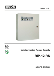
Orion ISS
Extinguishing Control and
Indicator Module
S2000-PT
User’s Manual
This User’s Manual is intended to help for studying operability principles and maintenance of the
S2000-PT Extinguishing Control and Indicator Module of version 1.01.
Please read the instructions completely before connecting, operating, adjusting, or
maintaining this product.
The following terms are used throughout the Manual:
Alarm Loop (or Loop, or LP): The electrical circuit with non-addressable fire or intrusion detectors
(or other non-addressable devices) included. Actuation of a single detector brought in an alarm
loop causes breaking of the loop as a whole, so the actuated detector can be located only with
the accuracy of the alarm loop
Zone: A minimal part of a security and safety installation that can be monitored and controlled
independently. Depending on the context, the term ‘zone’ can imply an alarm loop, an
addressable detector, a hardwire component, etc.
Partition: A set of zones that can be user controlled as a whole. As a rule, zones fall into partitions
depending on their location (e.g., one partition can involve all zones at one individual area)
Network Address: A unique number of the module (1 to 127) within the local RS-485 network of the
Orion integrated security system
Network Controller: A hardware/software which monitors for and controls the devices of the Orion
integrated security system. It can be an S2000(M) console or a PC with installed Orion Pro
software
S2000-PT
Table of Contents
General ............................................................................................................................................... 5
Specifications .................................................................................................................................... 9
Operation Principles ........................................................................................................................ 13
Indication .................................................................................................................................. 14
Light Indication of Module Statuses
14
Light Indication of Partition Statuses
14
FIRE LED
TROUBLE LED
LOCKED LED
AUTO LED
EXTINGUISHING LED
14
15
15
15
16
Light Indication of Alarms and Troubles in Partitions
16
Sound Indication of Partition Statuses and User Requests
17
Light Indication of the Reader
17
Agent Release Control .............................................................................................................. 18
Events and Commands Transferred to the Network Controller ................................................. 21
Installation ........................................................................................................................................ 23
Standard Delivery ..................................................................................................................... 24
Safety Precautions .................................................................................................................... 24
S2000-PT Mounting .................................................................................................................. 24
Wiring the RS-485 Interface Line .............................................................................................. 25
Connecting a Power Supply ...................................................................................................... 26
Getting Started.......................................................................................................................... 26
Programming ................................................................................................................................... 27
Module Settings ........................................................................................................................ 30
Network Controller Settings ...................................................................................................... 33
Adding the S2000-PT to the Configuration of the Network Controller
33
Creating Partitions
35
Adjusting the Network Controller for Receiving Control Commands
36
Maintenance ..................................................................................................................................... 41
Inspecting Module’s Operation Conditions ................................................................................ 43
Testing the S2000-PT in Self-Diagnostic Mode ......................................................................... 43
Checking for Communication Conditions over the RS-485 Interface ......................................... 44
3
www.bolid.com
Orion ISS
Testing the iButton Reader and Its LED ................................................................................... 44
Troubleshooting........................................................................................................................ 45
www.bolid.com
4
S2000-PT
General
GENERAL
5
www.bolid.com
Orion ISS
The S2000-PT Extinguishing Control and Indicator Module (hereinafter referred to as the module)
is designed to operate within Orion Integrated Security Systems as a device for remote managing
a number (up to ten) of S2000-ASPT devices, each assigned with a specific partition of the Orion
system and managing a specific agent releasing application.
The module provides:
Light indication of statuses of related partitions (related S2000-ASPT),
Light and (optionally) sound indication of various alarms and troubles in related partitions,
Remote releasing extinguishing agent and remote cancellation of releasing extinguishing
agent for related applications,
Enabling and disabling the automatic mode of releasing extinguishing agent for related
applications.
Remote control of fire extinguishing processes by the S2000-PT is performed through the network
controller. The network controller can be either an S2000M fire and alarm console of versions 2.03+
or a PC with Orion Pro software installed.
The S2000-PT receives an information about statuses of related partitions (related S2000-ASPT) from
the network controller over the RS-485 interface representing this information by means of light and
sound indication.
In addition, if programmed, the S2000-PT transfers the network controller user commands to turn
on / off automatic mode of releasing extinguishing agent and to start / cancel starting releasing. The
network controller, upon receiving such a command, analyses the received data, makes a decision
about gaining access to the requested operation, and, if access is granted, retranslates the executive
command to the relevant S2000-ASPT.
To establish authorized remote control of releasing extinguishing agent, a reader of iButtons (Touch
Memory access devices) can be connected to the S2000-PT. In such case controlling system
partitions through the S2000-PT is available for users within 30 seconds after touching their iButtons
to the reader, these iButtons being pre-registered by the network controller with specific rights to
control specific partitions.
The S2000-PT has a built-in sounder which is used to indicate alarms and troubles in the system
partitions assigned to this S2000-PT. Sounds can be silenced either manually, by pressing the
SILENCE button, or automatically, upon elapsing the programmed operation time.
The module can be powered by a power supply providing 12 V or 24 V dc. It is advised to use Bolid
manufactured battery backed power supplies of series RIP-12 or RIP-24.
The module is equipped with a tamper switch. On changing tamper switch’s statuses the module
sends the network controller relevant messages about tampering / restoring its enclosure.
www.bolid.com
6
S2000-PT
General
All the messages about S2000-PT events such as power failures, enclosure tampering / restoring,
turning on / off the automatic mode of releasing extinguishing agent, starting / canceling starting agent
releasing applications as well as resetting sound alarms by an operator are sent to the network
controller. In case of a loss of communication over the RS-485 interface such messages are collected
in the non-volatile memory of the S2000-PT (up to 16 messages) and, on restoring communications,
they are transferred to the network controller with the time and date of origin specified by the internal
S2000-PT clock.
The module is to be programmed using the tool of configuring all the devices of the Orion system, the
UProg.exe (of version 4.0.0.825 and above). All settings of the S2000-PT are stored in the module’s
non-volatile memory.
The last version of the UProg.exe can be downloaded from the site of the Bolid Company at the
address of www.bolid.com in Software section. The module is connected to the PC where the
UProg.exe is installed via the S2000M console switched to the Interface Converter or Programming
mode as well as via one of the Bolid manufactured interface converters PI-GR, S2000-PI, S2000USB, USB-RS485.
The S2000-PT module is attached within premises near an operator’s work place at locations
protected against atmospheric fallouts and mechanical damage and is designed for round-the-clock
operation. The module is not suitable for operation in corrosive or dusty environments as well as firehazardous areas.
The S2000-PT module (see Figure 1) has ten indicator strings «1» to «10» (1) designed to indicate
statuses of up to ten agent releasing applications related with the module. Each indicator string of 5
two-color LEDs can display such events or statuses in the related partitions as fire detector’s
responding, S2000-ASPT troubles, and locking start of the related agent releasing application as well
as display the current mode of releasing (automatic or manual) and the current status of the
extinguishing system operating. So, each indicator string of the module is intended to display statuses
of a single S2000-ASPT device.
In addition, each indicator string contains two control buttons (2) pushing which switches on / off the
automatic mode of starting fire extinguishing application as well as remotely starts / cancel starting the
application.
Seven single-color LEDs (4) at the right are designed to indicate alarms and troubles retranslated by
the network controller from the S2000-ASPT related to the module.
READY LED (3) indicates conditions of the S2000-PT itself.
The module has a built-in sounder which indicates receiving alarms from partition related to the
S2000-PT. The SILENCE button (5) is designed to reset sounding manually.
7
www.bolid.com
Orion ISS
3
2
4
1
5
Figure 1
www.bolid.com
8
S2000-PT
Specifications
SPECIFICATIONS
9
www.bolid.com
Orion ISS
21 Control Buttons
Number of Partitions
10
Alarm and Trouble Indicators
10 strings of five LEDs each to indicate statuses of
10 related partitions,
7 LEDs to indicate alarms and troubles in all related
partitions,
READY LED to indicate statuses of the S2000-PT itself
Internal Sounder
Built-in
Tamper Switch
Built-in
Event Log Capacity
16 events
RS-485 Communication Port
Yes
Transmission Rate
9600 Bd
Data Transmission
Half-duplex
Power Supply
External 12 V to 24 V dc
Bolid manufactured RIP-12 or RIP-24 battery backed
power supplies are advisable
Input Voltage
10.2 ÷ 28.4 V dc
Input Power
3 W max
Consumed Current
Alarm Mode
250 mА max @ 12 V,
130 mА max @ 24 V,
Quiescent Mode
30 mА max @ 12 V,
(all LEDs are on)
20 mА max @ 24 V,
Pre-Operation Time
2 s max
External Reader
One Reader Input to connect an external iButton reader
Output Interface
Touch Memory (1-Wire, µ-LAN)
Reader LED
One LED controlled by logical +5 V CMOS levels with
current values being restricted by 10 mA at direct
connection
Operating Temperatures
www.bolid.com
−30 °С to +50 °С
10
S2000-PT
Specifications
Ingress Protection Rating
IР20
Overall Dimensions
170 mm х 340 mm х 25.5 mm
Weight
0.6 kg
Average Lifetime
10 years
Device Programming
By means of the UProg.exe, the tool for configuring
devices of an Orion system
Connection to a PC
Over the RS-485 interface bus via one of the Bolid
manufactured interface converters PI-GR, S2000-PI,
S2000-USB, USB-RS485
11
www.bolid.com
Orion ISS
www.bolid.com
12
S2000-PT
Operation Principles
OPERATION PRINCIPLES
13
www.bolid.com
Orion ISS
INDICATION
The S2000-PT module is equipped with 50 LEDs (indicator strings “1” to “10”) to indicate statuses of
ten related partitions, the READY LED to indicate statuses of the module itself, and 7 LEDs to
represent alarms and troubles of various types which are happening in the part of the system related
to the S2000-PT at the time.
In addition, the S2000-PT is equipped with a sounder and can issue various audible signals for
various events.
The partitions which statuses are indicated by the S2000-PT should be formed by a System
Administrator (the descriptors of the partitions should be added to the network controller
configuration), and the numbers of these partitions should be linked to the relevant indicator strings
“1” to “10” in the S2000-PT configuration (see Section Module Settings).
If a reader is connected to the module then the reader LED indicates user-to-system interaction on
user’s requesting access to control releasing extinguishing agent by S2000-PT buttons.
Light Indication of Module Statuses
Operating conditions of the module S2000-PT are indicated by the green LED “READY” as follows:
Norm (quiescent mode)
On
No communication over the RS-485 interface
Flashes twice per second
Programming
Flashes four times per second
In case of loss of the communications over the RS-485 interface within 15 to 30 seconds, READY
starts flashing twice per second (provided that the input power is in norm). The LED stop flashing and
returns to steady lighting after restoring communications.
Light Indication of Partition Statuses
Statuses of the ten Orion system partitions assigned with the module are indicated by relevant
indicator strings each containing five LEDs namely FIRE, TROUBLE, LOCKED, AUTO, and
EXTINGUISHING.
FIRE LED
A FIRE LED indicates receiving responses of fire detectors connected to alarm loops of the related
S2000-ASPT as well as statuses of the S2000-ASPT’s zones of manual and remote releasing of
extinguishing agent.
www.bolid.com
14
S2000-PT
Operation Principles
If any zone of the related partition (either a zone of alarm loops with connected fire detectors or one of
the zones of manual and remote releasing) has entered the Fire Alarm status then the partition is also
assigned to the Fire Alarm status. If there is no zone in the Fire Alarm status but at least one zone
has entered the Fire Prealarm status then the partition is assigned to the Fire Prealarm status. If the
partition has just entered the Fire Alarm status and at another zones a Fire Prealarm message is
received then FIRE LED behavior will not change.
On module’s receiving from the network controller messages about resetting alarms on the S2000ASPT related to the partition, the FIRE LED is turned off.
The behavior of FIRE LEDs from the highest to the lowest priorities of partition statuses is as follows:
FIRE ALARM
Flashes in red twice per second
FIRE PREALARM
Flashes in red once per two seconds
Norm
Off
TROUBLE LED
The TROUBLE LED indicates such troubles and faults occurred during operating the related S2000ASPT as alarm loop troubles, troubles of S2000-ASPT executive outputs, power troubles, enclosure
tampering, and loss of communication between the S2000-ASPT and the network controller. The
partition is considered to be in the Trouble status is there is one of the troubles listed above in this
one.
TROUBLE
Flashes in red once per two seconds
Norm
Off
LOCKED LED
The LOCKED LED is turned on when releasing extinguishing agent for the related application cannot
be started (for example, the door to the protected premises is open during counting the Pre-discharge
Delay).
Release is locked
Lit steady in red
Norm
Off
AUTO LED
The AUTO LED shows which mode is currently set for releasing extinguishing agent at the application
related with the partition: automatic (on responding fire detectors connected to the S2000-ASPT) or
manual (on receiving a manual alarm from the manual call point connected to the S2000-ASPT or a
remote release command from the network controller).
15
www.bolid.com
Orion ISS
The AUTO button has
Flashes in green and red alternately twice per second until the
just been pushed
relevant command is executed or rejected (see Section Agent
Release Control)
The automatic mode of
Lit steady in green
releasing agent is turned on
The automatic mode of
Off
releasing agent is turned off
EXTINGUISHING LED
Each EXTINGUISHING LED indicates various steps of operating of the agent releasing application
related to this indicator string.
EXTINGUISHING button has
Flashes in green and red alternately twice per second until the
just been pushed
relevant command is executed or rejected (see Section Agent
Release Control)
Pre-discharge Delay
Flashes in red once per two seconds
Release
Flashes in red twice per second
Release Fault
Flashes in yellow once per second
Agent is being released
Lit steady in red
Releasing cancelled
Off
Quiescent Mode
Off
Light Indication of Alarms and Troubles in Partitions
Summarized statuses of all the partition assigned to the module are showed by alarm indicators FIRE
and PREALARM as well as by trouble indicators LOOP, OUTPUT, POWER, COMMUNICATION, and
TAMPERING at the right part of the S2000-PT.
The summarizing indicator FIRE indicates presence of a fire in one or more partitions related to the
module by flashing in red once per second.
The summarizing indicator PREALARM is turned on (flashes in red once per two seconds) if one or
more of the partitions related to the module have entered the Prealarm status.
Indicator of TROUBLE group at the right part of the module flashes in yellow once per two seconds if
there is a relevant trouble in one or more partitions:
LOOP
Trouble of the alarm loop of an S2000-ASPT
OUTPUT
Trouble of the relay output of an S2000-ASPT
www.bolid.com
16
S2000-PT
Operation Principles
POWER
Main power failed or power trouble of an S2000-ASPT
COMMUNICATION
No communication with an S2000-ASPT over the RS-485 bus
TAMPERING
The enclosure of an S2000-ASPT is open
Sound Indication of Partition Statuses and User Requests
The sounder of the S2000-PT operates as follows:
Fire Alarm
Issues long beeps each two seconds
Fire Prealarm
Issues two beeps once per two seconds
Trouble
Issues a beep once per four seconds
User Request (an iButton is touched to
Issues a beep
the reader)
Illegal Code (the iButton has no rights
Issues a long sound (about 1 s)
for requested operation)
Access Granted
Issues two beeps
If several partitions related to the S2000-PT have various statuses which should be indicated,the
sounder indicates the status with the highest priority. Fire Alarm is the status of the highest priority,
the Fire Prealarm is the status of lower propriety, and the Trouble status is of the lowest priority.
Sounds can be silenced by pushing the SILENCE button. When the SILENCE button is pressed the
module sends the S2000М or the computer the Alarm Cancelled message.
Sound signaling also can be stopped automatically after elapsing a time programmed for the module
(see Section Module Settings). No messages about automatic silencing are sent to the network
controller.
Light Indication of the Reader
If a reader is connected to the module, the LED of the reader indicates the following events:
A user has touched his or her iButton to the
The reader LED flashes twice per second
reader (User Request)
The iButton toched to the reader has no rights The reader LED is off
for requested operation (Illegal Code)
The requested operation is allowed (Access
The reader LED lights within 30 s
Granted)
17
www.bolid.com
Orion ISS
AGENT RELEASE CONTROL
The S2000-PT has two control buttons for each of the ten related partitions. The AUTO button
switches the current mode of releasing extinguishing agent from automatic to manual and back. The
EXTINGUISHING button allows remote releasing or cancelling release of extinguishing agent.
For authorized control by AUTO and EXTINGUISHING buttons, a user shall touch his iButton (key) to
a reader connected to the S2000-PT. The key shall be enrolled by the network controller. Also the key
shall be assigned to a number of partitions which are enabled for this key to control as well as to
specific rights to control the partitions (see Section Adjusting the Network Controller for Receiving
Control Commands). These partitions, in turns, shall be assigned to the indicator strings of the S2000PT (see Section Module Settings).
The S2000-PT can also be assigned to a built-in password (an access code) which enables
controlling partitions without user authorization by Touch Memory devices. This alternative can be
used when the module is located at a place protected against unauthorized access. The password (or
PIN code, or access code) is programmed in the configuration of the S2000-PT using the UProg.exe
(see Section Module Settings). This password shall also be enrolled in the configuration of the
network controller with relevant rights to control relevant partitions (see Section Adjusting the Network
Controller for Receiving Control Commands).
In case of user’s touching his iButton to the S2000-PT reader, the module sends the code of the
iButton to the network controller over the RS-485 interface. The network controller verifies the
received code, the module sounder being activated for 0.25 s and the module LED flashing 2 times
per second.
If the presented iButton is enrolled in the network controller configuration, then the Access Granted
signal sounds and the module LED is lit steady for 30 seconds. After that the user can control
partitions by using AUTO and EXTINGUISHING buttons within 30 seconds.
On user’s pressing a button the module sends the network controller the request for executing the
relevant control command (turning on / off the automatic mode of releasing extinguishing agent or
remote release / cancel releasing extinguishing agent). The network controller considers the received
request and makes an access decision.
If the electronic key has all the required access rights, the network controller transfer the control
command to the relevant S2000-ASPT (see below) and then returns the module the result of the
operation via the RS-485 interface.
If the iButton is not registered by the network controller, then touching it to the module reader causes
issuing the Illegal Code sound and the module LED is turned off.
www.bolid.com
18
S2000-PT
Operation Principles
If presenting electronic keys is not needed for controlling partitions, then on pressing one of the
buttons AUTO or EXTINGUISHING the S2000-PT sends the network controller over the RS-485 the
relevant request and its build-in password (access code). The network controller considers the
received request and makes an access decision.
If the module access code is enrolled in the configuration of the network controller (see Section
Adjusting the Network Controller for Receiving Control Commands) and have rights for the requested
operation, then the network controller sends the relevant executive command to the S2000-ASPT
related to the pressed button (see below) and then returns the S2000-PT the result of operation over
the RS-485 interface.
If, otherwise, the access code of the S2000-PT is not written in the configuration of the network
controller, the Illegal Code signal sounds.
If the module password is enrolled in the network controller configuration but have no rights to control
releasing extinguishing agent, then user’s pressing on an AUTO or EXTINGUISHING button causes
the LED adjacent to the button to flash until the requested command is rejected (see Section In case
of loss of the communications over the RS-485 interface within 15 to 30 seconds, READY starts
flashing twice per second (provided that the input power is in norm). The LED stop flashing and
returns to steady lighting after restoring communications.
Light Indication of Partition Statuses).
In such cases when permission to control an S2000-ASPT device from the S2000-PT is granted, the
AUTO and EXTINGUISHING buttons operates as follows:
To activate the automatic mode Push the AUTO button if the relevant LED is turned off
of releasing extinguishing agent
To disable the automatic mode of Push the AUTO button if the relevant LED is turned on
releasing extinguishing agent (the
manual mode only)
To release extinguishing agent
Push the EXTINGUISHING button for more than 3 s
To cancel releasing
Push the EXTINGUISHING button shortly, within 0.2 s to 1 s
Pushing an AUTO button of the S2000-PT entails giving the relevant S2000-ASPT a command for
changing the current mode of starting the connected fixed extinguishing system. If the automatic
mode (starting on receiving responses from fire detectors) is in force, this mode will be switched to the
manual mode (starting on pressing a manual call point or receiving the relevant command from the
network controller), and vice versa.
Pushing an EXTINGUISHING button of the S2000-PT entails giving the relevant S2000-ASPT a
command to start releasing extinguishing agent or to abort releasing, depending on its current status.
19
www.bolid.com
Orion ISS
If the agent releasing application has just been started, then on short-time pushing the
EXTINGUISHING button the application will be stopped.
Otherwise, if the agent releasing application is not started, on pushing the EXTINGUISHING button
for more than 3 s the related S2000-ASPT enters the modes Fire Alarm and Pre-discharge Delay
when the S2000-ASPT begins counting the programmed pre-discharge delay and the EXIT light table
is turned on.
Upon the expiration of the pre-discharge delay the S2000-ASPT enters the Release mode. In this
mode the S2000-ASPT generates a starting pulse and gives a command to activate connected
modules S2000-KPB. The EXIT table is turned off while the KEEP OUT table is turned on. Upon the
expiration of the starting pulse the S2000-ASPT enters the Extinguishing mode if pressure sensors in
the extinguishing agent control circuit have responded.
www.bolid.com
20
S2000-PT
Operation Principles
EVENTS AND COMMANDS TRANSFERRED TO THE NETWORK CONTROLLER
The S2000-PT automatically sends the network controller over the RS-485 interface the following
messages about its states:
TAMPER ALARM
The module enclosure is open
TAMPER RESTORED
The module enclosure is closed
ALARM RESET
The SILENCE button is pressed on receiving an alarm
DEVICE RESTART
The watchdog timer is reset
The S2000-PT provides buffering events sent to the network controller over the RS-485 interface.
If a communication loss occurred during generating a message lasts more than one minute then the
relevant event is stored in the non-volatile memory of the S2000-PT. When the communication is
restored, the event will be transmitted via the RS-485 interface to the network controller with the time
and date assigned in accordance with the internal clock of the module.
The network controller synchronizes the internal clock of the S2000-PT to its own clock by automatic
sending a Synchronize Clock command transferred via the RS-485 interface (commonly, at the
beginning of each hour).
The S2000-PT sends the network controller over the RS-485 bus the following commands:
SET AUTO MODE
Pushing an AUTO button when the related AUTO LED is off
SET MANUAL MODE
Pushing an AUTO button when the related AUTO LED is on
RELEASE»
Pushing an EXTINGUISHING button for more than 3 s
CANCEL RELEASING
Quick pushing an EXTINGUISHING button
The commands said above are sent only after user’s granting access to control partitions (see Section
Agent Release Control)
21
www.bolid.com
Orion ISS
www.bolid.com
22
S2000-PT
Installation
INSTALLATION
23
www.bolid.com
Orion ISS
STANDARD DELIVERY
Find the following unpacking the S2000-PT:
The S2000-PT Control and Indicator Module
The data sheet
CD disk with this User’s Manual
Four woodscrews 1- 4х40.016 with wall plugs
Note:
Access devices DS1990A and a reader such as Schityvatel-3 or similar should be
ordered and supplied separately.
SAFETY PRECAUTIONS
There are no potential hazard circuits within the module
Do SHUT OFF the power from the module before mounting, wiring, or maintaining
the S2000-PT
Mounting and maintenance the S2000-PT must be performed by qualified engineers
S2000-PT MOUNTING
Figure 2 display the appearance of the module as well as its overall and mounting dimensions.
The S2000-PT is to be attached to walls or any other structures near the operator’s location in
premises protected against atmospheric fallouts and mechanical damage.
Mount the module and its connecting lines in accordance with the Wiring Diagram (see Figure 3).
Attach the module at the height of 1.5 meters above the floor.
www.bolid.com
24
S2000-PT
Installation
Figure 2. Overall and Mounting Dimensions of the S2000-PT
WIRING THE RS-485 INTERFACE LINE
Connect RS-485 interface lines as shown in the electric wiring diagram below (see Figure 3).
S2000-PT
RS-485B
1
RS-485A
2
0V
3
0V
+U
4
(12…24) V
Ind
5
0V
6
ТМ
7
To an S2000М console or PC
To a power supply
Touch Memory
reader
Figure 3. Wiring Diagram for S2000-PT Operating
25
www.bolid.com
Orion ISS
To connect the module to the network controller via the RS-485 interface bus, attach its RS-485A and
RS-485B terminals to the A and В lines of RS-485 bus respectively. Wires are connected to the
S2000-PT by means of its screw terminal block. The maximum wire cross-section area is 1.5 square
millimeters. If the module is neither the first nor the last device within the RS-485 bus, remove the
jumper set on the module PCB near the RS-485A and RS-485B terminals.
WARNING! If the RS-485 interface bus is quite long (more than 1000 meters), use twisted-pair
cabling to connect the devices. The resistance value of each RS-485 interface line (A or B) measured
between the network controller and the most distant device MUST NOT exceed 200Ω.
While wiring the RS-485 interface bus, you are advised to configure the device network as “the bus”
(that is, connect devices in a chain). If a long-distance branch (more than 50 meters from the RS-485
bus) needs to be made, an S2000-PI interface repeater (produced by the Bolid Company) is to be
included at the cross point. The number of successively included repeaters is not restricted.
CONNECTING A POWER SUPPLY
Connect a power supply of 10 V to 28 V to the 3 and 4 terminals of the module (see Figure 3). We
recommend you to use Bolid manufactured power supplies of RIP series.
Couple the 0 V circuits of the S2000-PT and the network controller. If both the devices are connected
to a single power supplies, their 0 V circuits need not be coupled.
GETTING STARTED
After mounting the S2000-PT and its connecting lines turn the module’s power supply on. The
READY LED of the module shall light in green.
The S2000-PT to work as a part of an Orion system under control of a network controller, it must be
assigned to a unique network address (see Section Module Settings).
www.bolid.com
26
S2000-PT
Programming
PROGRAMMING
27
www.bolid.com
Orion ISS
To program the S2000-PT module for operating your specific functions, give or change settings of the
configuration parameters stored in its non-volatile memory by doing the following.
Connect the module to a computer via one of the Bolid manufactured interface converters (such as
PI-GR, S2000-PI, S2000-USB, or USB-RS485) or through the S2000М console (which should be
switched to the programmed mode as described in its Manual). The tool for configuring the devices of
the Orion system, UPpog.exe, of versions 4.0.0.825 and above must be run on this computer.
After running the UProg its working window is opened on the PC display. At the top part of the window
there are the Main Menu and the Toolbar. Select the Device → Read Device Configuration command
(or press <Ctrl+F3>, or select the
icon from the toolbar).
Figure 4
The window for searching devices will be output on the display. Specify the number of the logic COM
port the S2000-PT is connected to, and the UProg will start searching the devices connected to this
COM port of the PC (see Figure 4). As a result of this searching, list of all found devices with their
network addresses and version numbers will be shown at the display (see Figure 5).
Figure 5
www.bolid.com
28
S2000-PT
Programming
Select the entry for the S2000-PT by left mouse clicking, and then click the Select button. The UProg
will display the window with current settings of the S2000-PT (see Figure 6).
After opening the window with settings, the S2000-PT module enters the programming mode, with its
READY LED flashing 4 times per second.
Figure 6. The Work Window of the UProg for Configuring the S2000-PT
You can also get an access to the module settings by loading the S2000-PT configuration from the
relevant file with .cnu extension written to any data storage, using the File →Load Configuration File
command (or the <F3> button, or the
toolbar icon).
Besides, a new configuration file can be created by using the File → New Configuration menu
command (or the <Ctrl+N> button, or the
toolbar icon).
The command File → Base Configuration is intended for loading factory setting values to the empty
configuration created in the UProg.
29
www.bolid.com
Orion ISS
The newly created or revised configuration can be:
Loaded to the module memory
, or Device → Write Configuration to This Device
Loaded to the memory of another Device → Write Configuration to Another Device
connected S2000-PT with specified
network address
Saved to a file of the internal UProg
, or <F2>, or File → Save Configuration to File
format with the .cnu extension
Written as a text to an MS Word file
, or File → Export Configuration to MS Word
MODULE SETTINGS
The configuration parameters shown in Table 1 define the general operating features of the S2000-PT
as well as its network parameters for operating as a part of an Orion ISS system.
Table 1. Configuration Parameters of the S2000-PT Module
Parameter
Description
Range
Factory Value
Network Address
A unique number of the module in the RS485 interface bus
1 to 127
127
Partition Number
A number of that partition in the network
controller configuration which is linked
with each string of status indicators of the
module
0 to 9999
1 to 10
Sound Duration
The time after elapsing which the module
sounder is automatically turned off
0 s to 255 s
0s
Access Code
A four-digit password with which the
S2000-PT is registered in the network
controller database as a user having
some rights to control fire extinguishing
0000 to 9999
Empty
The Network Address parameter is intended to identify uniquely the module in the Orion device
system. The module sends messages and receives commands from the network controller only using
the address specified by this parameter. The network address must be unique for each Orion system
device.
To program or change the network address of the module, select the command Device→
Change Device Address in the menu of the UProg and enter the proper number in the range
of 1 to 127 in the appeared dialog box (see Figure 7).
www.bolid.com
30
S2000-PT
Programming
The network address of the S2000-PT can also be programmed or changed by means of the network
controller as described in its Manual.
Figure 7
In order the indicator strings 1 to 10 displays statuses of actual partitions of the Orion system
programmed in the network controller database, these indicator strings should be linked to the
partitions by the set of Partition Number parameters.
To set or change a Partition Number, left clock the field of the programmed indicator string
and enter the partition number into the relevant dialog box in the upper part of the UProg
window (see Figure 6). For unused indicator strings set the partition Number to zero.
31
www.bolid.com
Orion ISS
The Sound Duration parameter defines the time of module sounder’s being turned on when an alarm
is received.
To set or change the Sound Duration, enter a proper value ranged from 0 to 255 to the
relevant dialog box at the bottom of the UProg window (see Figure 6):
0
– if sound signaling of the module is to be disabled,
1-254 – the time in seconds since module’s receiving an alarm until the sounding is turned
off automatically,
255
– to disable automatic silencing: sounder will be on until the SILENCE button is
pressed.
The Access Code parameter defines a built-in password (PIN code) of the module and allows user to
get access to control partitions without access devices Touch Memory. The S2000-PT sends this
password to the network controller over the RS-485 interface when the user pushes one of the AUTO
or EXTINGUISHING buttons.
The password (access code) should also be enrolled in the database of the network controller (see
Section Adjusting the Network Controller for Receiving Control Commands).
To set or change an Access Code, enter a four-digit code into the Access Code dialog box
at the bottom of the UProg window (see Figure 6).
Let the field empty or clear it if controlling partitions by the S2000-PT without presenting
electronic keys is prohibited.
www.bolid.com
32
S2000-PT
Programming
NETWORK CONTROLLER SETTINGS
Adjust a network controller by means of the PProg.exe if it is an S2000М or by means of Database
Administrator software if the Orion Pro software operates the system.
To program the network controller to operate the S2000-PT, do the following:
Enroll the S2000-PT to the network controller database;
Create the relevant partitions;
Enroll all the relevant users with their authenticators (PIN codes or access devices) to the
network controller database and assign the users to the rights to control the created
partitions;
Enable the S2000-PT to control these partitions.
This Manual describes the procedures of programming an S2000М console by means of the
PProg.exe. Before working with this program the console should be switched to the programming
mode as described in its manual. If Orion Pro software is used as the network controller, program the
software as described in the Orion Pro’s documentation.
The last version of the PProg.exe can be downloaded from the site of the Bolid Company at the
address of www.bolid.com.
Adding the S2000-PT to the Configuration of the Network Controller
1.
Run the PProg.exe selecting a number of the COM port which the S2000M console is connected
to in the Search window on the Devices tab and clicking the Start Searching button
. On finishing
the procedure of searching a list of all connected devices will be appeared. Each device in the list is
shown with its address, type, and version number (see Figure 8). After program’s finding the console
its configuration can be written or read. Read the console configuration by the menu command
S2000 → Read Configuration. You can also create a new configuration by the menu command
File → New.
2.
Add the S2000-PT to the tree of the devices by dragging and dropping it from the Search window
to the Devices window with left mouse button (see Figure 9). The Inspector (Device) window is
designed for displaying, entering, and editing the parameters of a selected device.
33
www.bolid.com
Orion ISS
Figure 8
Figure 9
You can add the S2000-PT to the S2000М configuration and set its parameters manually if the
module is not connected to the console. For doing so, click on the Add button
, enter the network
address of the module in the Inspector (Device) window, select its type (S2000-PT) from the
dropdown list, and specify the version number (1.01).
www.bolid.com
34
S2000-PT
Programming
Creating Partitions
1.
Go to the Partitions (Zones) page of the PProg using the button
2.
Create a new partition by clicking the button
.
(see Figure 10).
Figure 10
3.
In the Partitions (Zones) window select the proper S2000-ASPT which will be assigned to the
created partition, and drag and drop its descriptor to the upper window, on the partition descriptor
(see Figure 11). All zones of the selected S2000-ASPT will be added to the partition.
35
www.bolid.com
Orion ISS
Figure 11
Adjusting the Network Controller for Receiving Control Commands
To adjust the S2000-PT to send control commands, you must define the user rights to control the fire
extinguishing system as well as module’s rights to control specified partitions in the configuration of
the network controller.
User rights are defined via assigning a user to an Access Group. Each Access Group is a set of
user rights which consists of a list of partitions enabled for controlling and actions permitted for each
partition.
For an S2000-PT a user can be allowed to perform such actions as turning on and off the mode of
automatic releasing extinguishing agent as well as remote starting / cancelling the start of the fixed
fire extinguishing installation.
1.
To create an Access Group, go to the Access Group page of the PProg clicking the button
2.
Create a new Access Group by clicking on
.
. In the Inspector (Access Group) window select
the proper number and type the name or a short comment (optionally) of the Access Group (see
Figure 12).
www.bolid.com
36
S2000-PT
Programming
Figure 12
3.
In the Partitions window select the partitions which are enabled to be controlled for this Access
Group. Move them up, on the created access group descriptor by left mouse button (see Figure
13).
Figure 13
37
www.bolid.com
Orion ISS
4.
In the Access Groups window select the partition and give the rights to control this partition in the
Inspector (Rights) window.
Then you should assign the programmed Access Group with the PIN-code (the Access Code) of the
S2000-PT or with user authenticators, entering / presenting which will be considered by the network
controller as an authorized command to get access to partition control. For doing so:
1.
Go to the Authenticator page of the PProg clicking on
2.
Create a new descriptor clicking the button
.
(see Figure 14).
Figure 14
3.
Enroll the first user iButton. For doing so click on the Read Key button
and select the system
reader the iButton will be touched to. Then touch the access device to the reader. The code of the
device shall be shown in the Code field (see Figure 15).
4.
Enter the user name and assign the authenticator to the proper Access Group in the Inspector
(Authenticator) window. The type of the authenticator (Key) shall be defined by the program
automatically.
www.bolid.com
38
S2000-PT
Programming
Figure 15
5.
Repeat steps 2 to 4 for all the user electronic keys which are to be enrolled.
6.
If users are to be allowed to control partitions without presenting iButtons, register the built-in
password of the S2000-PT. Add a new descriptor by clicking the button
and enter the access
code of the S2000-PT to the Code field of the Inspector (Authenticator) window. This code must
be the same as the code programmed for the S2000-PN in its configuration (see Section Module
Settings). Then enter the name (or comment) of this authenticator to the User field and assign the
S2000-PT access code to the Access Group which, in turns, is assigned to partitions which will be
controlled by users from the S2000-PT. The type of the authenticator (Password) will be defined
by the program automatically.
Rights of the module (to control partitions) are programmed by defining the list of the partitions
allowed to be controlled by the S2000-PT in the network controller configuration. To program control
rights of the S2000-PT:
1.
Go to the Device Rights page of the PProg by clicking the button
2.
In the Partitions window select the partitions which are allowed to be controlled by users operated
.
the S2000-PT (both with and without touching their Touch Memory devices). Move selected
partitions to the Device Rights window on the S2000-PT descriptor by left mouse button (see
Figure 16).
39
www.bolid.com
Orion ISS
Figure 16
Finally, the changed or newly created configuration of the console can be:
Loaded to the console
, S2000 → Write Configuration
Saved in text format to a file with the
, File → Save, File → Save As
.txt extension or encrypted to a file
of .gpc format
www.bolid.com
40
S2000-PT
Maintenance
MAINTENANCE
41
www.bolid.com
Orion ISS
To make sure the S2000-PT keeps proper operability it shall be inspected by a competent specialist
at least on receipt and annually. The inspection algorithm shall include:
Visual checking the S2000-PT for contaminations and mechanical damage,
Verifying the S2000-PT for secure mounting and wire connection conditions,
Inspecting operability of the S2000-PT in accordance with the techniques discussed below.
Inspection of the S2000-PT shall be performed by competent personnel of the Service Company.
On completing the inspection the results shall be written into an S2000-PT maintenance log book.
If during the warranty period the module does not meet any requirements set forth in this section, this
will be the grounds to raise a climb to the manufacturer.
The module should be inspected under the following ambient conditions:
− Relative humidity: 45 % ÷ 80 %;
− Ambient temperature: 25 °С ±10 °С;
− Atmospheric pressure 630 ÷ 800 mm Hg.
Power off the module before connecting and disconnecting wires. Take into
account the pre-operation time of the module which shouldn’t exceed 2 s
www.bolid.com
42
S2000-PT
Maintenance
INSPECTING MODULE’S OPERATION CONDITIONS
1.
Wire the S2000-PT for inspection as shown in Figure 17, but not connecting the wires of the RS485 bus to the S2000М console.
2.
Turn the module power on.
3.
The READY LED of the S2000-PT shall be lit steady in green for a time and then flash once per
second.
4.
Measure the current consumed by the S2000-PT. The value of the current shall not exceed
300 mA.
S2000М
RS-485B
1
1 RS-485B
RS-485A
2
2 RS-485A
0V
3
+U
4
+U
1
0
2
S2000-PT
RIP-12
(RIP-24)
А
3
+U
4
0
Figure 17. Wiring the S2000-PT for Functional Testing
TESTING THE S2000-PT IN SELF-DIAGNOSTIC MODE
To start self-diagnostic procedure, push SILENCE button three times shortly and then once more
long1.
If the module is operable its LEDs are turned on as follows:
1.
Columns of indicators “1” to “10” are turned on one-by-one in red, and then one-by-one in green;
2.
Strings of indicators “1” to “10” are turned on one-by-one in red, and then one-by-one in green;
3.
All status indicators and single-color indicators are turned on together, status indicators being kit
in red;
4.
All status indicators and single-color indicators are turned on together, status indicators being kit
in green;
5.
The single-color indicators FIRE, COMMUNICATION, and OUTPUT flash.
On pressing on an AUTO or EXTINGUISHING button the relevant LED is turned on.
1
Here “shortly” means keeping the button pressed for 0.1 to 0.5 s while “long” means keeping the button
pressed for at least 1.5 s. Pauses between pushing shall be 0.2 to 1 s.
43
www.bolid.com
Orion ISS
The S2000-PT exits the self-diagnostic mode automatically after 10 s since last pushing an AUTO or
EXTINGUISHING button or on pressing the SILENCE button.
CHECKING FOR COMMUNICATION CONDITIONS OVER THE RS-485 INTERFACE
1.
Connect wires of the RS-485 bus to the S2000М console.
2.
Apply power to the S2000-PT module and S2000M console.
3.
The READY LED shall be lit steady in green.
4.
Within a minute since powering, the console shall display messages about founding and resetting
the device with the network address of the S2000-PT. If several messages are received which
were collected in the module buffer they can be listed by and buttons of the console.
TESTING THE IBUTTON READER AND ITS LED
1.
Disconnect the S2000М console from the RS-485 interface bus.
2.
Touch the reader by the iButton.
3.
The reader LED shall flash.
www.bolid.com
44
S2000-PT
Maintenance
TROUBLESHOOTING
On starting the S2000-PT
Check if the power is supplied to the input power terminals of the
the READY LED is not
S2000-PT
turned on
The READY LED flashes
Verify whether the module communicates with the network
once per second
controller through the RS-485 bus correctly or not
Ensure the lines А and В of the RS-485 bus are properly
connected to the contact terminals of the S2000-PT, swap them
if necessary
The module is not found by
Verify whether the network address of the module is correct and
the network controller
change it if necessary
Ensure the lines А and В of the RS-485 bus are properly
connected to the contact terminals of the S2000-PT, swap them
if necessary
Upon pushing one of the
Check if an access code is programmed for the module in its
buttons
or
configuration (see Section Module Settings). If so, check if this
nothing
access code is enrolled as a password in the network controller
AUTO
EXTINGUISHING
happens
configuration and assigned to an access group with the relevant
control rights. If, otherwise, no access code if programmed and
users are allowed to control partitions only by presenting their
electronic keys to the module reader then check if the relevant
keys are programmed with the relevant rights in the network
controller configuration (see Section Adjusting the Network
Controller for Receiving Control Commands).
Check if the module itself is allowed to control partitions in the
network controller configuration (see Section Adjusting the
Network Controller for Receiving Control Commands).
Amend the module or the network controller settings if
necessary.
45
www.bolid.com
BOLID ONE YEAR LIMITED WARRANTY
Bolid Company and its divisions and subsidiaries («Seller»), 4 Pionerskaya Str., Korolev 141070, Moscow
Region, Russia warrants its security equipment (the «product») to be free from defects in materials and
workmanship for one year from date of original purchase, under normal use and service. Seller’s obligation is
limited to repairing or replacing, at its option, free of charge for parts or labor, any product proven to be defective
in materials or workmanship under normal use and service. Seller is not responsible for results where the
product is used improperly, where it is used for any application it is not intended for, used under unacceptable
environmental conditions and mishandled or stored under improperly. Seller shall have no obligation under this
warranty or otherwise if the product is altered or improperly repaired or serviced by anyone other than the
Seller. In case of defect, contact the security professional who installed and maintains your security equipment
or the Seller for product repair.
This one year Limited Warranty is in lieu of all other express warranties, obligations or liabilities. THERE ARE
NO EXPRESS WARRANTIES, WHICH EXTEND BEYOND THE FACE HEREOF. ANY IMPLIED
WARRANTIES, OBLIGATIONS OR LIABILITIES MADE BY SELLER IN CONNECTION WITH THIS
PRODUCT, INCLUDING ANY IMPLIED WARRANTY OF MERCHANTABILITY, OR FITNESS FOR A
PARTICULAR PURPOSE OR OTHERWISE, ARE LIMITED IN DURATION TO A PERIOD OF ONE YEAR
FROM THE DATE OF ORIGINAL PURCHASE. ANY ACTION FOR BREACH OF ANY WARRANTY,
INCLUDING BUT NOT LIMITED TO ANY IMPLIED WARRANTY OF MERCHANTABILITY, MUST BE
BROUGHT WITHIN 12 MONTHS FROM DATE OF ORIGINAL PURCHASE. IN NO CASE SHALL SELLER BE
LIABLE TO ANYONE FOR ANY CONSEQUENTIAL OR INCIDENTAL DAMAGES FOR BREACH OF THIS OR
ANY OTHER WARRANTY, EXPRESS OR IMPLIED, OR UPON ANY OTHER BASIS OF LIABILITY
WHATSOEVER, EVEN IF THE LOSS OR DAMAGE IS CAUSED BY THE SELLER’S OWN NEGLIGENCE OR
FAULT. Some countries do not allow limitation on how long an implied warranty lasts or the exclusion or
limitation of incidental or consequential damages, so the above limitation or exclusion may not apply to you.
Seller does not represent that the product may not be compromised or circumvented; that the product will
prevent any personal injury or property loss by burglary, robbery, fire or otherwise; or that the product will in all
cases provide adequate warning or protection. Buyer understands that a properly installed and maintained
alarm may only reduce the risk of a burglary, robbery, fire or other events occurring without providing an alarm,
but it is not insurance or guarantee that such will not occur or that there will be no personal injury or property
loss as a result. CONSEQUENTLY, SELLER SHALL HAVE NO LIABILITY FOR ANY PERSONAL INJURY,
PROPERTY DAMAGE OR OTHER LOSS BASED ON A CLAIM THE PRODUCT FAILED TO GIVE WARNING.
HOWEVER, IF SELLER IS HELD LIABLE, WHETHER DIRECTLY OR INDIRECTLY, FOR ANY LOSS OR
DAMAGE ARISING UNDER THIS LIMITED WARRANTY OR OTHERWISE, REGARDLESS OF CAUSE OR
ORIGIN, SELLER’S MAXIMUM LIABILITY SHALL NOT IN ANY CASE EXCEED THE PURCHASE PRICE OF
THE PRODUCT, WHICH SHALL BE THE COMPLETE AND EXCLUSIVE REMEDY AGAINST SELLER. This
warranty gives you specific legal rights, and you may also have other rights which vary from country to country.
No increase or alteration, written or verbal, to this warranty is authorized.
4 Pionerskaya Str., Korolev 141070,
Moscow Region, Russia
Phone/fax: +7 495 775-7155
Email: [email protected], [email protected]
www.bolid.com