1
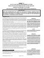
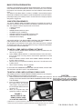
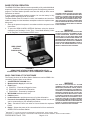
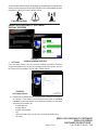
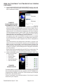
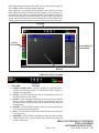
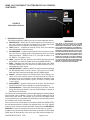
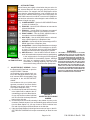
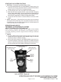
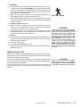
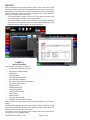
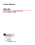
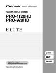
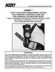
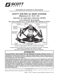
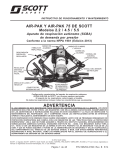
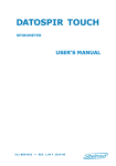
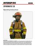
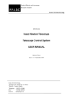
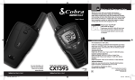
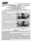
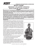
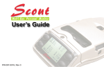
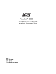
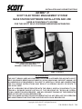
INSTALLATION AND USE INSTRUCTIONS
SEMS® II
SCOTT ELECTRONIC MANAGEMENT SYSTEM
BASE STATION SOFTWARE INSTALLATION AND USE
USER ACCOUNTABILITY SYSTEM
FOR THE SCOTT SELF-CONTAINED BREATHING APPARATUS
SEMS II BASE STATION PCMCIA CARD
(SHOWN WITH REQUIRED
PERSONAL COMPUTER, NOT INCLUDED)
SEMS® II CONSOLE
WARNING
THE SCOTT SEMS II USER ACCOUNTABILITY SYSTEM IS INTENDED FOR USE WITH SCOTT
SELF-CONTAINED BREATHING APPARATUS (SCBA) WHICH MAY SUPPORT HUMAN LIFE
IN HAZARDOUS ATMOSPHERES. FAILURE TO CAREFULLY READ AND UNDERSTAND
THE FOLLOWING INSTRUCTIONS MAY RESULT IN SERIOUS INJURY OR DEATH TO
THE SCBA USER.
USE OF A RESPIRATOR INTEGRATED WITH THE SEMS II USER ACCOUNTABILITY SYSTEM W I L L R E Q U I R E M O D I F I C A T I O N O F T H E R E S P I R A T O R " R E G U L A R O P E R A TIONAL INSPECTION PROCEDURES" AND WILL REQUIRE TRAINING OF THE RESPIRATOR
USER IN THE USE OF SUCH RESPIRATORS.
THE FOLLOWING INSTRUCTIONS SUPPLEMENT BUT DO NOT REPLACE THE OPERATING
AND MAINTENANCE INSTRUCTIONS SUPPLIED WITH EACH RESPIRATOR.
Copyright © 2009, SCOTT, All Rights Reserved
Page 1 of 16
P/N 595186-01 Rev B 7/09
SEMS® II
SCOTT ELECTRONIC MANAGEMENT SYSTEM
BASE STATION SOFTWARE INSTALLATION AND USE
USER ACCOUNTABILITY SYSTEM
FOR THE SCOTT SELF-CONTAINED BREATHING APPARATUS
WARNING
READ AND UNDERSTAND THIS COMPLETE INSTRUCTION MANUAL BEFORE USING A
RESPIRATOR EQUIPPED WITH A SEMS II ACCOUNTABILITY SYSTEM. IMPROPER USE OF
THE SEMS ACCOUNTABILITY SYSTEM MAY LEAD TO A FAILURE OF THE SYSTEM WHICH
COULD RESULT IN SERIOUS INJURY OR DEATH.
INTRODUCTION
The SEMS II Accountability System is intended to be used as an integral part
of an emergency incident management system which includes planned deployment of personnel and radio communications. The Incident Commander
can use the SEMS II Accountability System to maintain an awareness of
the assigned location and function of all users of properly equipped SCOTT
respirators assigned to the incident.
Users of this system must be familiar with the capabilities as well as the limitations of the system. The SEMS II Accountability System provides valuable
information about the status of respirator users as well as limited two-way
communications for such things as Evacuation notices and PASS activation.
Properly equipped systems can also provide SCOTT PAK-TRACKER™ tracking capability to find lost or down personnel. The PAK-TRACKER function
may not be activated on some retrofitted units. Contact your SCOTT Service
Center for details.
The SEMS II Accountability System does NOT replace conventional two-way
radio communications. The SEMS II Accountability System does NOT replace
the minimum two person team approach to personnel deployment.
Before using the SEMS II Accountability System, review your standard operating procedures for emergency incident management. Use these instructions to
become familiar with the features and capabilities of the SEMS II Accountability
System. Then determine the best way to incorporate the SEMS II Accountability System into your emergency incident management procedures. Train
all personnel thoroughly before use of the system in a real life incident.
Refer to the SEMS II Personal Distress Alarm (PDR) and Base Station Operation and Maintenance Instructions, SCOTT P/N 595166-01, for complete
details of use of the SEMS II Personal Distress Alarm when used with an
approved SCOTT SCBA.
The SEMS II Accountability System communicates only with Firefighter Resources (Respirator Users) using a SCOTT SCBA equipped with the SEMS
II Accountability System integrated into the Personal Distress Alarm. Other
Firefighter Resources who are not using a properly equipped SCOTT respirator may be added for accountability purposes, but they will not be accessible
through the communications functions of the system.
If the equipment does not work as described in these instructions, remove the
equipment from service and tag for repair by authorized personnel.
QUESTIONS OR CONCERNS
If you have any questions or concerns regarding use of this equipment, contact
your authorized SCOTT distributor, or contact SCOTT at 1-800-247-7257 (or
704-291-8300 outside the continental United States) or visit our web site at
www.scotthealthsafety.com.
P/N 595186-01 Rev B 7/09
Page 2 of 16
WARNING
Do not operate this equipment while under the influence of drugs, alcohol, or
any medications or substances which
MAY affect vision, dexterity, or judgment. USERS OF THIS EQUIPMENT must be
IN GOOD physical and mental health in
order to operate safely. Do not USE this
equipment WHEN FATIGUE PREVENTS SAFE
OPERATION. Stay alert when operating
this equipment. Inattention or carelessness while operating this equipment may
result in serious injury or death.
NOTE
USE IN ACCORDANCE WITH NFPA 1500, "STANDARD ON FIRE DEPARTMENT OCCUPATIONAL
SAFETY AND HEALTH PROGRAM."
WARNING
The SEMS II Accountability System
communicates only with Firefighter
Resources (Respirator Users) using a
SCOTT SCBA equipped with the SEMS II Accountability System integrated into the
Personal Distress Alarm. Other Firefighter Resources who are not using
a properly equipped SCOTT respirator
may be added for accountability purposes, but they will not be accessible
through the communications functions
of the system. FAILURE TO RECOGNIZE THE
STATUS OF FIREFIGHTER RESOURCES MAY
RESULT IN SERIOUS INJURY OR DEATH.
WARNING
IF THE EQUIPMENT DOES NOT OPERATE AS
DESCRIBED IN THESE INSTRUCTIONS, REMOVE
THE EQUIPMENT FROM SERVICE AND TAG
FOR REPAIR BY AUTHORIZED PERSONNEL.
FAILURE TO DETERMINE THAT THE EQUIPMENT IS OPERATING PROPERLY MAY LEAD TO
A SITUATION WHICH may result in serious
injury or death.
BASE STATION PREPARATION
Operation of the SEMS II Accountability System Base Station requires installation
of the SEMS II MESH GATEWAY KIT, SCOTT P/N 200772-01, which includes
the Graphic User Interface (GUI) Software and the PCMCIA Communications
Card.
The SEMS II PDR Base Station consists of a SEMS II Accountability System
Base Station PCMCIA Card installed in a Windows® based Personal Computer,
preferably a laptop (not included). SCOTT recommends use of a laptop computer
designed for rugged use.
COMPUTER REQUIREMENTS
The SCOTT SEMS II MESH GATEWAY software is PC based and requires a
minimum of Windows® XP Service Pack 2 OR Windows Vista Service Pack 1 (32
Bit). The computer hardware requirements are as follows:
– 1.6GHz Processor
– 1 GB RAM
– 500MB available hard drive space
– CD-ROM Drive (for installation)
– Available PCMCIA slot (for SEMS II gateway radio)
– Available USB port (for RFID card programmer)
– 1024x768 screen display
NOTE
YOU MUST INSTALL THE SEMS II MESH GATEWAY SOFTWARE FIRST BEFORE INSTALLING THE PCMCIA CARD IN THE COMPUTER.
Also provided on the software CD are copies of the User Instructions in Adobe®
Acrobat®2 format (pdf). You may download a free copy of Adobe Acrobat Reader
from www.Adobe.com/AcrobatReader.
TO INSTALL SEMS II MESH GATEWAY SOFTWARE
1. Place the SCOTT SEMS II MESH GATEWAY software CD-ROM in the CD
drive on your computer.
2. Select “SEMS II MESH INSTALL” to install the Software. Follow the instructions on the screen. You may need to close all other applications to install
this program.
3. When the installer creates a folder called “SEMS II MESH GATEWAY” for
the files, select “Continue.”
4. When the set up is completed successfully, select “OK.” You will return to the
Installer screen.
5. When finished installing, close the Installer.
NOTE
IF YOU HAVE ANY PROBLEMS INSTALLING THE SOFTWARE, DO NOT USE
THE SYSTEM. CONTACT SCOTT FOR ASSISTANCE.
TO INSTALL SEMS II MESH GATEWAY PCMCIA CARD
After installing the SCOTT SEMS II MESH GATEWAY software on your computer,
install the PCMCIA Communications Card as follows:
1. Hold the PCMCIA Communications Card as shown in FIGURE 1 with the antenna
pointing UP. DO NOT HANDLE THE PCMCIA COMMUNICATIONS CARD BY
THE ANTENNA.
2. Insert the PCMCIA Communications Card into the PC Card slot
until it snaps in. The power LED on
the card will light GREEN when the
computer is on.
3. When your computer says "New
equipment installed," select OK.
CAUTION
DO NOT HANDLE THE PCMCIA COMMUN I C AT I O N S C A R D B Y T H E A N T E N N A .
OVERSTRESSING THE ANTENNA MAY DAMAGE
THE INTERNAL COMPONENTS OF THE CARD.
FIGURE 1
INSTALLATION OF THE
SEMS II PCMCIA CARD
IN A LAPTOP COMPUTER
1
2
WINDOWS® is a registered trademark of MICROSOFT CORPORATION, Redmond, Washington
Adobe® and Adobe Acrobat® are registered trademarks of Adobe Systems, San Jose, California
Page 3 of 16
P/N 595186-01 Rev B 7/09
BASE STATION OPERATION
The SEMS II PDR Base Station must be operated by a fully trained individual
as part of a complete incident management system and respiratory protection
program. The Base Station Operator must have the ability to direct rescue
operations as needed.
If using a battery powered portable computer, be sure the battery is fully
charged before beginning use at an incident.
The Base Station must be located in a safe, non-hazardous and non-flammable area away from the hazardous atmosphere where the respirators are
being used.
1. Start-up the personal computer in accordance with the computer’s user
instructions.
2. To open the SEMS II MESH GATEWAY Software, select the shortcut
created on your Desktop or in the “Tyco – Scott Health & Safety” folder
in “All Programs” in the Windows START menu.
SEMS II BASE
STATION
PCMCIA CARD
WARNING
THE SEMS II BASE STATION MUST BE MONITORED BY A FULLY TRAINED INDIVIDUAL WITH
THE ABILITY TO DIRECT RESCUE OPERATIONS
AT ALL TIMES WHEN LOGGED-IN RESPIRATOR
USERS MAY BE IN A HAZARDOUS AREA. FAILURE TO PROVIDE A PROPERLY TRAINED BASE
STATION OPERATOR MAY PERMIT A SITUATION
TO OCCUR WHICH COULD RESULT IN SERIOUS
INJURY OR DEATH.
WARNING
DO NOT TAKE THE BASE STATION INTO A FIRE
OR INTO A POTENTIALLY FLAMMABLE OR EXPLOSIVE ATMOSPHERE. OPERATE THE BASE
STATION ONLY IN A SAFE AREA AWAY FROM
THE HAZARDOUS ATMOSPHERE WHERE THE
RESPIRATORS ARE BEING USED. USE OF THE
BASE STATION IN A POTENTIALLY FLAMMABLE
OR EXPLOSIVE ATMOSPHERE MAY CAUSE IGNITION OF THE ATMOSPHERE WHICH COULD
RESULT IN SERIOUS INJURY OR DEATH.
FIGURE 2
SEMS II BASE STATION PCMCIA CARD INSTALLED IN
A PANASONIC3 TOUGHBOOK4 LAPTOP PERSONAL COMPUTER
BASIC FUNCTIONS OF THE SOFTWARE
The Primary functions of the Base Station Software to monitor SEMS II Accountability System Users are as follows:
1. ACCEPT/REJECT/ASSIGN Users
2. Monitor the Air Supply of each User
3. EVAC Signal
a) EVAC ALL – Evacuate all logged in Users
b) EVAC IND – Selected User Evacuation
c) EVAC ASSN – Evacuate by Assignment
4. WITHDRAW Notification from User
5. PASS Activation
6. Incident Record to provide an account of incident information
7. Personnel Accountability Report (PAR ) Timer reminder can be set
can be set according to your standard procedures.
8. Time – Records the time from when a User activates the respirator/
PASS.
9. Range – Shows the status of the communication link from each active
SEMS II PDR to the Base Station.
3
4
WARNING
The SEMS II Accountability System
communicates only with Firefighter
Resources (Respirator Users) using a
SCOTT SCBA equipped with the SEMS II Accountability System integrated into the
Personal Distress Alarm. Other Firefighter Resources who are not using
a properly equipped SCOTT respirator
may be added for accountability purposes, but they will not be accessible
through the communications functions
of the system. FAILURE TO RECOGNIZE THE
STATUS OF FIREFIGHTER RESOURCES MAY
RESULT IN SERIOUS INJURY OR DEATH.
PANASONIC® is a registered trademark of PANASONIC CORPORATION JAPAN, OSAKA, JAPAN.
Toughbook® is a registered trademark of PANASONIC CORPORATION OF NORTH AMERICA, SECAUCUS NEW JERSEY.
P/N 595186-01 Rev B 7/09
Page 4 of 16
The EVAC/WITHDRAW, PASS, and RANGE icons that appear on the software
display are the same as the EVAC/WITHDRAW, PASS, and RANGE symbols
tht appear on the PDA Control Console display.
EVAC/WITHDRAW
PASS
RANGE
SEMS II ACCOUNTABILITY SOFTWARE
DISPLAY SCREENS
FIGURE 3
OPENING SCREEN DISPLAYS
1. SETTINGS
From the Setup screen, you can enter the Incident Information, Division/
Group and Assignments, set the alert Sounds used by the system, and set
the Personnel Accountability Report (PAR) TIMER options.
FIGURE 4
SETTINGS DISPLAY
a) Each use of the SEMS II Base Command System Software is tracked as
an “Incident.” In the Setup, at a minimum you must enter an “Incident
Location” to name the session of use before proceeding. You may also
add optional information for:
• Incident Number
• Incident Name
• Incident Commander
• City
• State (this field has a pop-up menu to select the state name)
• Zip Code
Page 5 of 16
SEMS II ACCOUNTABILITY SOFTWARE
DISPLAY SCREENS
CONTINUED ON NEXT PAGE...
P/N 595186-01 Rev B 7/09
SEMS II ACCOUNTABILITY SOFTWARE DISPLAY SCREENS
CONTINUED...
b) In the DIVISIONS/GROUPS AND ASSIGNMENTS section, name and
Add the active Divisions/Groups and the projected assignments that
will be used at the incident.
FIGURE 5
DIVISIONS/GROUPS AND
ASSIGNMENTS DISPLAY
Divisions/Groups and Assignments can be entered to keep track of
groups of respirator users/firefighter resources at an incident. The Divisions/Groups and Assignments entered here will appear in the main
display screen. You must decide the appropriate use of the Divisions/
Groups and Assignments for each incident. This may change depending on the nature of the incident, on the available resources, and the
established roles and responsibilities of those resources.
As respirator users log-in to the SEMS II system, they can be added
to Divisions/Groups or to Assignments. As assignments change during the course of the incident, respirator users can be reassigned as
needed.
The Divisions/Groups and Assignments information is stored in the
software memory of the Personal Computer (not the PCMCIA card).
When you start a new incident on the same Personal Computer, the
Divisions/Groups and Assignments you entered at the last incident will
reappear. If necessary, use the Setup screen to change this information
for a new incident.
Set the Personnel Accountability Report (PAR) Timer in this window. The
Timer can be set from 5 to 90 minutes in increments of 5 minutes.
c) Select the SOUNDS section to set the different sounds for each of the
primary alert functions:
• EVAC Alarm
• Pressure Alarm
• PASS Alarm
• Out-of-Range Alarm
• PAR Timer Alarm
FIGURE 6
SOUNDS DISPLAY
The SEMS II Base Command System Software comes with a set of Default
alert sounds that emulate the sounds created by a SCOTT SCBA that is
equipped with the SEMS II electronics. These sounds may be changed
by the user in the Sounds screen.
Choose "Use Default" for the Default sounds or "Use Custom" to select
sounds from your computer.
P/N 595186-01 Rev B 7/09
Page 6 of 16
After all Setup selections have been made, click on "Exit Setup" to begin use
of the SEMS II Base Command System Software.
When logged on, all the SEMS II PDA Portable Units communicate to the
Base Station both directly and through other logged on units forming a communications "mesh network" to the Base Station. This extends the range for
the units furthest away from the Base Station. Because of this mesh network
system, the signal strength of each user as displayed on the Base Station may
change as the network constantly re-adjusts to the movement of the users.
TOOLBAR
ACTION
BUTTONS
ACCEPT/REJECT
SIDEBAR
USERS
DISPLAY
FIGURE 7
COMPLETE DISPLAY SCREEN
FIGURE 8
TOOLBAR
2. TOOL BAR
a) PCMCIA CONNECTION – Indicates whether the PCMCIA Card is
installed and operating. A RED "X" indicates the Card is either not
installed or not operating.
b) SETUP – The SETTINGS screens can be accessed at any time from
the SETUP button on the toolbar.
c) NOTES – Notes regarding the Incident can be entered in the NOTES
Screen. Each Note added will be date and time stamped when the
NOTES Screen is closed. All notes will be included at the end of the
Incident Report
d) REPORT – Use the REPORT button to view or print an Incident Report
for an incident that has been closed.
e) HELP – Provides software HELP Information similar to the information
in this instruction.
f) PAR TIMER – START/STOP of the PAR timer reminder. When the PAR
TIMER reaches 0:00, a "Call for Radio PAR" window will pop up and
an alarm may sound.
Page 7 of 16
SEMS II ACCOUNTABILITY SOFTWARE
DISPLAY SCREENS
CONTINUED ON NEXT PAGE...
P/N 595186-01 Rev B 7/09
SEMS II ACCOUNTABILITY SOFTWARE DISPLAY SCREENS
CONTINUED...
USER DETAIL
SIDEBAR
FIGURE 9
RESOURCES DISPLAY
3. RESOURCES DISPLAY
The Resources display is made up of nine (9) columns labeled as follows:
a) RESOURCE/ID – Shows the ID of the Respirator Users (Resources)
who have logged on and been accepted to the Incident. More than
twenty (20) users can appear on the display at one time.
b) TIME (minutes) – Indicates the amount of time since the individuals
have activated the SCBA electronics.
c) AIR PRESSURE – A graphic representation of the air pressure remaining in the User's air supply cylinder, using the same colors found in the
Heads-Up Display: GREEN for full to 1/2, YELLOW for below 1/2 to
1/4, RED for 1/4 cylinder or less.
d) PASS – Shows a RED icon when the User's PASS has been activated
and a GREY icon when the PASS has been ACKNOWLEDGED.
e) EVAC – Indicates who has been given an EVAC signal with a RED
EVAC/WITHDRAW icon. The icons turns to GREY when the user acknowledges the EVAC signal.
f) W/D (WITHDRAW) – Indicates a BLUE icon when the User has pressed
the WITHDRAW button on their Console. The icons turns to GREY
when the Base Station acknowledges the WITHDRAW signal.
g) RANGE – Indicates whether the individual User is still in Range. Because of this mesh network system, the signal strength of each user
as displayed may change as the network constantly re-adjusts to the
movement of the users. (GREEN = good, YELLOW = re-linking, RED
= out of range)
h) ASSIGNMENT – Shows the Assignment of the User. Use the Assign/
Detail ACTION BUTTON to change an individual's assignment.
i) DIVISION/GROUP – Shows the Division/Group of the User. Use the
Assign Division/Group button in the User Detail Sidebar to change an
individual's Division/Group.
The columns can be reorganized by clicking and dragging the column headings
to the desired order. In addition, clicking on the column heading will sort all
Resources by that column. For example, you could move the PASS column
to the far left and sort by the PASS column heading to show which Resources
are in PASS at the top left of the display.
If the end-of-service life indicators on a respirator (HUD and VIBRALERT®)
are activated because the cylinder has dropped below 1/4 of full capacity
(Low Air), the Air Pressure icon will show RED. If selected, the USER DETAIL
SIDEBAR will show the remaining air pressure of that user's air cylinder.
In addition, any user who has either an activated Low Air alarm or an activated
PASS alarm will automatically move to the top of the Resource display list.
P/N 595186-01 Rev B 7/09
Page 8 of 16
WARNING
The SEMS II Accountability System
communicates only with Firefighter
Resources (Respirator Users) using a
SCOTT SCBA equipped with the SEMS II Accountability System integrated into the
Personal Distress Alarm. Other Firefighter Resources who are not using
a properly equipped SCOTT respirator
may be added for accountability purposes, but they will not be accessible
through the communications functions
of the system. FAILURE TO RECOGNIZE THE
STATUS OF FIREFIGHTER RESOURCES MAY
RESULT IN SERIOUS INJURY OR DEATH.
4. ACTION BUTTONS
Action Buttons are brightly colored when they are active for
the selected Resource and turn grey when they have no
active functions. For example, the ACK PASS button will be
grey when the selected Resource is not in PASS mode. As
soon as the selected Resource goes into PASS mode, the
ACK PASS button will turn BLUE. Once the ACK PASS button has been selected to acknowledge the active PASS, the
button will again turn grey.
a) CLOSE INCIDENT – Use the CLOSE INCIDENT button
to close the Incident File.
b) EVAC IND – Use the EVAC IND button to evacuate the
selected individuals.
c) EVAC ALL – Use the EVAC ALL button to evacuate all
active personnel logged in to the SEMS II Incident.
d) EVAC ASSIGN – Use the EVAC ASSIGN button to
evacuate the selected ASSIGNMENTS.
e) ACK PASS – Use the ACK PASS button to acknowledge a PASS signal from a Respirator User.
f) ACK W/D – Use the ACK W/D to acknowledge a WITHDRAW signal from a Respirator User.
g) Assign/Detail – Use the Assign/Detail button to change
the selected individuals' current assignment, division,
or group. This will also open the User Detail Sidebar
showing the selected user's remaining air pressure.
h) ADD Resource – Use the ADD Personnel button to
enter information about a person/resource participating
in the incident who is not using an SCBA equipped
with the SEMS II Accountability System. Although
FIGURE10
ACTION BUTTONS they have no respirator status, interactive communications, or tracking capability, they can still be
accounted for along with all the other participants.
ACCEPT/REJECT SIDEBAR – Select
the Resource/ID Detail tab to open the
ACCEPT/REJECT Sidebar.
As Respirator users activate their systems, their individual SEMS II ID’s from
their scanned RFID Accountability Tags
will appear in the ACCEPT/REJECT
sidebar.
In accordance with your incident management procedures, the Base Station
Operator must choose either to Accept
or to Reject Respirator users.
a) Choose Accept All and all ID's showing
in the sidebar will be added to the accountability group for this Base Station.
FIGURE 11
Or you may choose to select individual
ACCEPT/REJECT/ASSIGN
user ID’s and click the Accept Selected
SCREEN
button on the side bar.
b) Choose Reject All and all ID's showing in the sidebar of users you do
not want to maintain as part of your accountability group will be removed
from this Base Station. Or you may choose to select individual user
ID’s and click the Reject Selected button on the side bar.
c) If the User Detail Sidebar is showing when a new user logs on, the ACCEPT/REJECT SIDEBAR will reopen automatically to show the new
user.
5.
Page 9 of 16
WARNING
The SEMS II Accountability System
communicates only with Firefighter
Resources (Respirator Users) using a
SCOTT SCBA equipped with the SEMS II Accountability System integrated into the
Personal Distress Alarm. Other Firefighter Resources who are not using
a properly equipped SCOTT respirator
may be added for accountability purposes, but they will not be accessible
through the communications functions
of the system. FAILURE TO RECOGNIZE THE
STATUS OF FIREFIGHTER RESOURCES MAY
RESULT IN SERIOUS INJURY OR DEATH.
P/N 595186-01 Rev B 7/09
BASE STATION OPERATOR RESPONSIBILITIES
1. RANGE
When logged on, all the SEMS II PDA Portable Units communicate to
the Base Station both directly and through other logged on units forming
a communications "mesh network" to the Base Station. This extends the
range for the units furthest away from the Base Station. Because of this
mesh network system, the signal strength of each user as displayed on
the Base Station may change as the network constantly re-adjusts to the
movement of the users.
a) After forty (40) seconds without a linked signal, the RANGE symbol
on the Control Console will turn YELLOW and the RANGE icon in the
line entry for the user on the Base Station display will turn YELLOW
indicating the system is trying ot relink with the user.
b) If relinking does not occur, the RANGE symbol on the Control Console
will flash and the RANGE icon on the Base Station display will turn RED.
The Base Station operator must respond to the user’s out of RANGE
signal in accordance with the organization’s incident management
program.
2. AIR SUPPLY MONITORING
a) When the air supply cylinder reaches one-quarter of full pressure, the
end-of-service-time indicators (EOSTI) will activate on the SCBA and
a LOW AIR signal will be sent to the Base Station. If enabled, the Base
Station will sound the LOW AIR audible alert twice.
b) The Base Station Operator must respond to the user’s low air signal
in accordance with the organization’s incident management program.
This may include issuing an EVAC signal to the individual with the low
air signal.
3. EVACUATION
a) To send an evacuation message to all accepted logged-in respirator
users, the Base Station operator selects the EVAC ALL button on the
Base Station. The EVAC message will be sent to all accepted logged-in
respirator users.
b) To send an evacuation message only to one selected respirator user,
the Base Station operator uses the cursor to select and highlight the
user to evacuate from the list of logged-in respirator users, and then
presses the EVAC IND button.
c) To send an evacuation message to respirator users on a particular Assignment, the Base Station operator first clicks on the EVAC ASSIGN
button. A pop-up window with the current Assignments will appear.
Highlight the Assignments to evacuate from the list, and then click the
EVAC ASSIGN button again.
d) As each respirator user receives an EVAC message, they must press
the Yellow RESET button on the Control Console to acknowledge the
message.
e) As each respirator user acknowledges the EVAC message, the EVAC
Icon on the Base Station will change color for that respirator user.
4. WITHDRAW
a) The respirator user may elect to leave the incident by pressing and
holding the Blue Withdraw button on the Control Console for two (2)
seconds. A BLUE EVAC symbol will appear in the line entry for the
user.
b) After the Base Station acknowledges the WITHDRAW message, the
EVAC symbol will change status and remain until user leaves the hazardous area and shuts down the respirator.
P/N 595186-01 Rev B 7/09
Page 10 of 16
WARNING
The SEMS II Accountability System
communicates only with Firefighter
Resources (Respirator Users) using a
SCOTT SCBA equipped with the SEMS II Accountability System integrated into the
Personal Distress Alarm. Other Firefighter Resources who are not using
a properly equipped SCOTT respirator
may be added for accountability purposes, but they will not be accessible
through the communications functions
of the system. FAILURE TO RECOGNIZE THE
STATUS OF FIREFIGHTER RESOURCES MAY
RESULT IN SERIOUS INJURY OR DEATH.
OTHER DISPLAY SCREEN FUNCTIONS
1. PAR Timer – Personnel Accountability Report Timer
a) In the DIVISIONS/GROUPS and ASSIGNMENTS Setup screen, the
PAR Timer can be set to a specific interval to remind the Base Station
Operator ask for a “PAR” from all involved personnel.
b) To start the PAR Timer, click on the PAR Timer START button.
c) When the PAR Timer reaches 0:00:00, a pop-up window will appear
saying "Call for Radio PAR." Click on the window to acknowledge and
close the window. The Base Station Operator must respond in accordance with the organization’s incident management program.
d) To stop the PAR Timer before it reaches 0:00:00, click on the STOP
button.
2. NOTE – Note screen – Select the Note icon to write a note or notes that
will be part of the incident log. Enter each NOTE and select OK to close
the NOTE screen. The note will be automatically time and date stamped. All
notes will be added to the incident report.
OPERATION AND USE OF
THE SEMS II ACCOUNTABILITY SYSTEM
USE OF THE SEMS II PDA PORTABLE UNIT
Users of SCOTT respirators equipped with the SEMS II PDA Portable
Unit must be fully trained in the operation of the equipment as part of
a complete respiratory protection program before entering a hazardous
environment.
1. Start-up
a) Use of the SEMS II PDA Portable Unit begins when the user opens the
cylinder valve on the respirator to start respirator usage. The unit will
sound three chirps to indicate activation.
b) After a brief start-up sequence, the GREEN SIGNAL Light on the Control Console will light. An alert tone, a “BE-doop” to indicate the system
activity, is used for several functions. Whenever the alert tone occurs,
the user should look at the Portable Unit display for information.
WITHDRAW BUTTON
(BLUE BUTTON)
MANUAL ALARM BUTTON
(RED BUTTON)
RESET BUTTON
(YELLOW BUTTON)
CONTROL
CONSOLE
DISPLAY
RED
SIGNAL
LIGHT
GREEN
SIGNAL
LIGHT
FIGURE12
THE CONTROL CONSOLE
OPERATION AND USE OF THE SEMS II ACCOUNTABILITY SYSTEM
CONTINUED ON NEXT PAGE...
Page 11 of 16
P/N 595186-01 Rev B 7/09
OPERATION AND USE OF THE SEMS II ACCOUNTABILITY SYSTEM
CONTINUED...
2. Initialization and RANGE
a) After the start-up sequence, the SEMS II PDA Portable Unit will send an
Initialization signal to the Base Station to log in. The Base Station will
respond by ACCEPTING the identity assigned to that Portable Unit.
b) If the respirator user moves too far from the Base Station after logging-in,
the RANGE symbol on the Control Console will change color indicating
RANGE
out of range until the user moves back into the Base Station field of
operation (up to one-half mile line-of-sight).
c) If the Portable Unit is too far away from the Base Station at start-up, or
if the Base Station is not turned ON, the RANGE symbol on the Control
Console display will light YELLOW immediately from start-up and not
be logged into the Base Station. The SEMS II PDA Portable Unit will
continue trying to log-in to a Base Station until one comes into range or
is turned ON.
d) Except for those functions which involve communication with the Base
Station, all PASS functions of the Control Console and SEMS II PDA
distress alarm are still operational when the Portable Unit is either out
of range or not logged into a Base Station.
3. PASS DISTRESS ALARM
a) The SEMS II PDA PASS distress alarm will operate in conjunction with
the Portable Unit. If the distress alarm on the respirator is activated,
either by the user pressing and holding the Red MANUAL ALARM button
for at least two seconds, or from the user being immobile for the required
time duration, the Portable Unit will send a PASS distress alarm signal
PASS
to the Base Station. This signal will override all other messages and
actions of the Portable Unit. The PASS symbol on the Control Console
will flash RED.
b) The PASS icon will appear RED on the Base Station display, and, if
enabled, the audible alert will sound. When the Base Station acknowledges the user’s distress signal by selecting the ACK PASS button on
the Base Station, the PASS symbol on the Control Console will turn
GRAY.
c) The distress alarm on the respirator will continue until the user shuts
down the respirator or resets the alarm.
4. EVACUATION
a) If the respirator users are required to leave the hazardous area, the
Base Station operator can send an evacuation message to the Portable
Units of logged-in respirator users. This message can be sent either to
all logged-in users (EVAC ALL), to everyone on and Assignment (EVAC EVAC/WITHDRAW
ASSIGN), or to individual logged-in users selected from the list on the
Base Station (EVAC IND).
b) The Portable Unit will emit the alert sound and the EVAC symbol will
begin flashing RED on the Control Console.
c) When an EVAC symbol begins flashing on the Control Console, the
respirator user must press twice the Yellow RESET button on the Control
Console to respond to the evacuation message. The EVAC symbol on
the Control Console will turn ON steady and the EVAC icon on the Base
Station display will turn GRAY until the user leaves the hazardous area
and shuts down the respirator.
P/N 595186-01 Rev B 7/09
Page 12 of 16
5. WITHDRAW
a) The respirator user may choose to leave the hazardous area. Pressing and holding the Blue WITHDRAW button for at least two seconds
will send that message to the Base Station. The EVAC symbol on the
Control Console will flash YELLOW quickly as the WITHDRAW message appears on the Base Station.
b) When the Base Station receives a user WITHDRAW message, the EVAC/WITHDRAW
Base Station Operator selects the ACK W/D button.
c) After the Base Station acknowledges, the EVAC symbol on the Control
Console will turn ON steady until user leaves hazardous area and shuts
down the respirator.
6. Air Supply Cylinder Pressure
a) When the cylinder reaches one quarter of full pressure, the SEMS
II PDA sounds a LOW AIR warning with an audible alarm as well as
WARNING
transmitting a LOW AIR alert to the Base Station.
THE RESPIRATOR USER MUST IMMEDIb) The LOW AIR alarm on the respirator will continue to operate until the ATELY LEAVE THE AREA REQUIRING RErespirator is shut down. This LOW AIR alarm is in addition to the other SPIRATORY PROTECTION WHEN AN END
OF SERVICE INDICATOR ALARM ACTUend-of-service indicators on the respirator.
ATES. ACTUATION OF AN END OF SER7. Shutdown
VICE INDICATOR ALARM WARNS THAT
a) After leaving the hazardous area and confirming that respirator use is A P P R O X I M A T E L Y 2 5 % O F F U L L PRES SURE REMAINS IN THE AIR SUPPLY CYLno longer required, doff the respirator according the user instructions I N D E R ( T H A T I S , A P P R O X I M A T E L Y 3 / 4
provided with the respirator.
OF THE TOTAL AIR SUPPLY HAS BEEN
USED). A DELAY IN LEAVING THE AREA
b) Close the cylinder valve.
AFTER ALARM ACTUATION MAY CAUSE
c) Press the Yellow RESET button twice.
DEPLETION OF BREATHING AIR SUPPLY
d) The Control Console will sound the alert tone. The SEMS II PDA Por- WHICH COULD RESULT IN SERIOUS INJURY
OR DEATH.
table Unit is now off.
TERMINATION OF USE
When use of the SEMS II Accountability System is no longer needed, click the
"Close Incident" button. Shut down the computer according to the operating
instruction provided with the computer.
To remove the PCMCIA Communications card, press the card eject button
next to the PC card slot. DO NOT HANDLE THE PCMCIA COMMUNICATIONS CARD BY THE ANTENNA.
Carefully fold the antenna down in line with the card and store the PCMCIA
Communications card in a safe place protected from heat, sunlight, and
moisture.
Page 13 of 16
CAUTION
DO NOT HANDLE THE PCMCIA COMMUN I C AT I O N S C A R D B Y T H E A N T E N N A .
OVERSTRESSING THE ANTENNA MAY DAMAGE
THE INTERNAL COMPONENTS OF THE CARD.
P/N 595186-01 Rev B 7/09
REPORTS
Select the Reports button in the Toolbar to view or print a report of all of the
activities of a particular SEMS II Accountability System Incident on a specific
Base Station. The software also provides a separate icon on the Desktop for
SEMS II Reporting. Reports can only be generated from closed incidents.
Two types of reports can be produced:
– An Incident Report contains a list of all of the events and actions that
occurred during the incident in chronological order.
– A Personnel Report lists the same information, but divided by individual
respirator users who participated in the incident listed alphabetically. Each
individual's events will be listed in chronological order.
FIGURE 13
REPORT SCREENS
Actions listed in the report will include:
• Incident Start/End Date and Time
• Acceptance on Base Station
• Assignment
• Re-Assignment
• User Activated Withdrawal
• Acknowledge Withdrawal
• Evacuation (All/Individual/Assignment)
• Evacuation Acknowledge
• PASS Activation
• PASS Acknowledge
• LOW AIR Activation
• LOW AIR Acknowledge
• Call for PAR
• Add Personnel
• User Shut Down SCBA
• NOTES entered during the incident.
Choose View to see a preview of either an Incident Report or a Personnel
Report.
All Notes added during the course of the incident will be included at the end
of the Report with their respective date and time stamps. Notes cannot be
edited after they become part of the report.
If you wish to print a copy of either report, choose Print and the report will be
sent directly to your available printer.
P/N 595186-01 Rev B 7/09
Page 14 of 16
SAFETY LISTINGS
FCC NOTICE
This equipment has been tested and found to comply with the requirements of United
States Federal Communications Commission, Code of Federal Regulations, FCC title
47, part 90 Section 20, limitation (27) and requirement Part 90.238 over frequency range
453.0375 to 465.6375 MHz, as well as FCC Section 1.1310 for Occupational/Controlled
Exposure limits.
If the SEMS II Base Station or Portable Unit has been damaged, DO NOT use this equipment. Maintenance or repair of this equipment must only be performed by an authorized
SCOTT service center. Unauthorized service may void the manufacturers warranty and
may cause damage to the equipment. Use only Scott authorized accessories, cables, and
power connectors. Consult the operating and service manuals for instructions on battery
replacement, battery maintenance, and use of accessory cables.
FCC COMPLIANCE
FCC Compliance Statement (Part 15.19)
This device complies with Part 15 of the FCC Rules. Operation is subject to the following two
conditions:
1. This device may not cause harmful interference, and
2. This device must accept any interference received,
Including interference that may cause undesired operation.
FCC Warning (Part 15.21)
Changes or modifications not expressly approved by the party responsible for compliance could
void the user’s authority to operate the equipment.
This portable transmitter with its antenna complies with FCC’s RF exposure limits for general
population / uncontrolled exposure.
The Pak-Tracker Locator Integrated Transmitter has been assigned FCC ID # T5E200451.
The SEMS II Control Console Transmitter has been assigned FCC ID # T5E200729.
CLASS B DIGITAL DEVICE
Note: This equipment has been tested and found to comply with the limits for a Class B digital
device, pursuant to Part 15 of the FCC Rules. These limits are designed to provide reasonable
protection against harmful interference in a residential installation. This equipment generates,
uses and can radiate radio frequency energy and, if not installed and used in accordance with
the instructions, may cause harmful interference to radio communications. However, there is
no guarantee that interference will not occur in a particular installation. If this equipment does
cause harmful interference to radio or television reception, which can be determined by turning
the equipment off and on, the user is encouraged to try to correct the interference by one or
more of the following measures:
– Reorient or relocate the receiving antenna
– Increase the separation between the equipment and receiver.
– Connect the equipment into an outlet on a circuit different from that to which the receiver is
connected.
– Consult the dealer or an experienced radio/TV technician for help.
INDUSTRY CANADA COMPLIANCE
Industry Canada Statement
The term “IC” before the certification / registration number only signifies that the Industry Canada
technical specifications were met.
Section 14 of RSS-210
The installer of this radio equipment must ensure that the antenna is located or pointed such that
it does not emit RF field in excess of Health Canada limits for the general population. Consult
Safety Code 6, obtainable from Health Canada’s web site: www.hc-sc.gc.ca/rpb.
Operation is subject to the following two conditions:
1) this device may not cause interference, and
2) this device must accept any interference, including interference that may cause
undesired operation of the device.
Page 15 of 16
P/N 595186-01 Rev B 7/09
RADIO FREQUENCY INTERFERENCE (RFI)
When any electronic device is adversely affected by radio waves, Radio
Frequency Interference (RFI) is said to have occurred. All electronic devices like the SEMS II distress alarm may be subject to the effects of RFI,
most of which are temporary in nature. Users of the SCOTT SCBA with the
integrated SEMS II distress alarm must be familiar with the normal operation
of the distress alarm and must also be familiar with how to identify and avoid
the effects of RFI (see DETECTING AND AVOIDING RADIO FREQUENCY
INTERFERENCE in the User Instructions provided with the SCOTT respirator equipped with the SEMS II Accountability System). If RFI occurs to the
SEMS II distress alarm, it may be caused by transmissions from hand-held
or personal radios where the radio antenna is touching or very close to (less
than 6 inches from) components of the SEMS II distress alarm. It may also
be caused by transmissions from radio base stations or high-powered vehicle
mounted radios or any other powerful source of electromagnetic radiation.
WARNING
RADIO FREQUENCY INTERFERENCE (RFI)
MAY CAUSE A MALFUNCTION OF THE SEMS
II PDA DISTRESS ALARM. USERS OF RESPIRATORS EQUIPPED WITH THE SEMS II
PDA DISTRESS ALARM MUST BE AWARE
OF THE PROPER OPERATION OF THE DISTRESS ALARM. FAILURE TO RECOGNIZE
A MALFUNCTION OF THE EQUIPMENT AND
TAKE PROPER CORRECTIVE ACTION MAY
RESULT FAILURE OF THE SEMS II PDA DISTRESS ALARM AND LEAD TO SERIOUS INJURY
OR DEATH.
EXPORT AND IMPORT
The international transport of the SCOTT SEMS II Accountability System and
portions thereof is regulated under United States export regulations and may
be regulated by the import regulations of other countries.
If you have any questions or concerns regarding these regulations, contact
SCOTT at 1-800-247-7257 (or 704-291-8300 outside the continental United
States).
Health & Safety Products
Monroe Corporate Center
PO Box 569
Monroe, NC 28111
Telephone 1-800-247-7257
FAX (704) 291-8330
www.scotthealthsafety.com
Printed in USA
P/N 595186-01 Rev B 7/09
Page 16 of 16