1
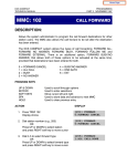
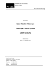
Home Page
SVMi-20E INSTALLATION
Installing the SVMi-20E in the Phone System
The SVMi-20E card can be installed in the OfficeServ 7000 Series Systems.
When installing an SVMi-20E card, it is important to remember that it is a computer, much the same as any desktop PC and it is therefore very important not to exceed these environmental limits.
Installing the SVMi-20E in an OfficeServ 7000 Series System
GENERAL
Q
POWER REQUIREMENTS
Because the SVMi-20E card does NOT draw from the -48DC supply it has a Zero (0) SEPU rating under all
possible configurations.
Q
OfficeServ 7000 Series HARDWARE COMPATIBILITY
Can only be installed in one of the DCS Card Slots in an expansion A or B cabinet.
Q
OfficeServ 7000 Series SOFTWARE COMPATIBILITY
All versions of the OfficeServ 7000 Series software support the SVMi-20E.
INSPECTION
Unpack and inspect the unit for any obvious damage. This card should be labeled SVMi-20E. If it is not, you have
the wrong card.
INSERTING THE CARD
NOTE: Before powering off the KSU, it is recommended that you use MMC 740 and set MBX Download to 'No'.
The SVMi-20E card can be installed in any slot (1 ~ 5) of any cabinet. Check that the OfficeServ 7000 Series
System’s power switch is in the OFF position. Next position the SVMi-20E card in the grooves of the card guide
and gently slide the card in until it makes contact with the connector. Press gently but firmly on the left and right
of the front edge of the card until the card seats in its connector. Press firmly on the Black Front Panel Lever until
it snaps securely in place. The cabinet can now be turned on.
If the SVMi-20E card is being installed in an existing (not new) system, you will have to use MMC 806 to pre install
the card and MMC 724 to assign extension numbers to each SVMi-20E port. Use any available numbers.
After the SVMi-20E card is installed, either in a new or existing system, you will have to use MMC 601 and assign
all the SVMi port numbers to the last available station group (Group Number 5039 by default).
The final step is to do a proper shut down on the SVMi-20E and once a t a C:> press the reset button on the front
of the SVMi-20E. (Steps for performing a proper shut down are described in the section Correct System
Shutdown.)
SVMi-20E Installation / September 2005
1
Home Page
Installing Individual SVMi-20E Components
Installing a Voice Processing Module
On the SVMi-20E VPMs are NOT required to access the first four embedded ports. VPMs are only necessary if
upgrading to larger port capacities. Adding new VPMs is as simple as plugging them in. There is no special programming to do in the SVMi-20E, the additional VPM card will be recognized when the system powers up.
However you may need to use MMC 724 to verify that all ports are assigned station numbers and you will need
to use MMC 601 to assign those station numbers to the last station group (Group Number 5039 by default).
INSTALLING THE VPM
If installing a VPM to a existing SVMi-20E installation, the SVMi-20E MUST be shut down properly (MMC 746) and
once down the OfficeServ 7000 Series System must be turned off before the SVMi-20E can be removed from the
OfficeServ 7000 Series System.
Discharge any static electricity you may have gathered by touching a ground point such as the cover of the KSU
Power Supply. When you have done this then lay the SVMi-20E card face up on a non-conductive surface.
Position the VPM over the card connector on the SVMi-20E PCB board and gently apply pressure until the card
seats.The SVMi-20E card can now be installed in the KSU. Once the SVMi-20E is securely seated in the OfficeServ
7000 Series System the KSU can be powered up.
Installing the Modem Daughter Board
PREPARATION
If installing a Modem Daughter Board into an existing SVMi-20E installation, the SVMi-20E MUST be shut down
properly (MMC 746) and once down the OfficeServ 7000 Series System must be turned off before the SVMi-20E
can be removed from the OfficeServ 7000 Series System.
Discharge any static electricity you may have gathered by touching a ground point such as the cover of the KSU
Power Supply. When you have done this then lay the SVMi-20E card face up on a non-conductive surface.
INSTALLATION
After you have either followed the above steps for an older installation or if you have a brand new SVMi-20E ready
to add the Modem Daughter Card, position the Modem Daughter Board component side down over the card connector on the SVMi-20E PCB board locate din the central area of the PCB and gently apply pressure until the card
seats.These connectors are keyed. When the Modem and the connectors are aligned properly the Modem should
easily snap into place. The SVMi-20E card can now be installed in the KSU. Once the SVMi-20E is securely seated
in the OfficeServ 7000 Series System the KSU can be powered up.
UNINSTALLING
After following the preparation steps mentioned above, gently separate the Daughter Board from the main PCB
connectors. The Modem Daughter Board should lift out with little effort. If you are replacing the Board follow the
Installation steps above for installing the replacement. If you are simply removing the Modem Daughter Board,
the SVMi-20E card can now be installed in the KSU. Once the SVMi-20E is securely seated in the OfficeServ 7000
Series System the KSU can be powered up.
SVMi-20E Installation / September 2005
2
Home Page
Installing the 64MB DRAM Module
PREPARATION
Preparation: If installing the 64MB DRAM Module in to an existing SVMi-20E installation, the SVMi-20E MUST be
shut down properly (MMC 746) and once down the OfficeServ 7000 Series System must be turned off before the
SVMi-20E can be removed from the OfficeServ 7000 Series System.
Discharge any static electricity you may have gathered by touching a ground point such as the cover of the KSU
Power Supply. When you have done this then lay the SVMi-20E card face up on a non-conductive surface.
After you have either followed the above steps for an older installation or if you have a brand new SVMi-20E ready
to add the 64MB DRAM Module, follow the steps outlined in this document in either the “Removing a Hard Disk
Drive” or “Removing the Compact Flash (CF) Adaptor” sections and remove the Drive that is installed on the unit
requiring the 64MB DRAM.
INSTALLATION
Once the Drive or Controller is removed, position the DRAM Module component side up with the copper edge
connections going into the DRAM connector on the SVMi-20E PCB. The DRAM connector is notched and the
DRAM Module should be held a 45 to 25 degree angle when inserting into the connector. Once inserted, gently
push down on the module until the notches on either side edge snap into place. Properly installed the DRAM
module will lay virtually parallel to the main SVMi-20E PCB. Follow the instruction in either the “Installing a Hard
Disk Drive” or “Installing the Compact Flash (CF) Adaptor” sections of this guide. Once the Drive is reinstalled the
SVMi-20E card can now be installed in the KSU. Once the SVMi-20E is securely seated in the OfficeServ 7000
Series System the KSU can be powered up.
UNINSTALLING
To uninstall the DRAM Module, follow the same preparation outlined in the beginning of this section. Once the
Drive or Controller is removed, gently pull the PLASTIC tabs on either side of the DRAM Module away from the
module with your thumb nails. The DRAM Module will pop up at a 25 to 45 degree angle. Gently pull the DRAM
from the DRAM socket. If replacing the existing DRAM follow the Installation section for installing the new DRAM.
If simply removing the DRAM for some other reason and you have eight ports or less then follow the instruction
in either the “Installing a Hard Disk Drive” or “Installing the Compact Flash (CF) Adaptor” sections of this guide.
Once the Drive is reinstalled the SVMi-20E card can now be installed in the KSU. Once the SVMi-20E is securely
seated in the OfficeServ 7000 Series System the KSU can be powered up.
SVMi-20E Installation / September 2005
3
Home Page
Installing or Removing the Hard Disk Drive
REMOVING A HARD DISK DRIVE (HDD)
1.
2.
3.
4.
5.
6.
7.
8.
Do a proper shut down of the SVMi-20E. (Steps for performing a proper shut down are described in the section Correct System Shutdown.)
Power down the phone system and remove the SVMi-20E card.
AVOID TOUCHING OR APPLYING PRESSURE TO THE TOP COVER OF THIS HDD.
HANDLE THIS UNIT ONLY BY THE SIDES.
Hold the unit with the HDD supported in your hand, held by the edges. The solder side of the card should be
facing up.
Remove the 4 retaining screws so that the HDD becomes detached.
Still holding the HDD by the edges invert the card (component side up) and gently unplug the ribbon cable.
Gently pack the HDD in the SEC provided packaging.
INSTALLING A HARD DISK DRIVE (HDD)
1.
2.
3.
4.
5.
Hold the HDD by the sides with the 4 screw studs facing up.
Attach the ribbon cable between the HDD and the Voice Mail card. The 4 spare pins on one end of the connector are not used.
Position the Voice Mail card with solder side up, so that the holes in the card line up with the studs on the
HDD adapter.
Insert the 4 screws, and tighten until snug. DO NOT OVERTIGHTEN.
Replace the SVMi-20E in the phone system.
Installing or Removing a Compact Flash Adapter
REMOVING THE COMPACT FLASH (CF) ADAPTER
1.
2.
3.
4.
5.
6.
Do a proper shut down of the SVMi-20E. (Steps for performing a proper shut down are described in the section Correct System Shutdown.)
Power down the phone system and remove the SVMi-20E card.
Hold the unit with the CF Adapter supported in your hand, held by the edges. The solder side of the card
should be facing up.
Remove the 4 retaining screws so that the CF Adapter becomes detached.
Still holding the CF Adapter by the edges invert the card (component side up) and gently unplug the ribbon
cable.
Gently pack the CF Adapter in the SEC provided packaging.
INSTALLING THE COMPACT FLASH (CF) ADAPTER
1.
2.
3.
4.
5.
Hold the CF Adapter by the sides with the 4 screw studs facing up.
Attach the ribbon cable between the CF Adapter and the Voice Mail card. The 4 spare pins on one end of the
connector are not used.
Position the Voice Mail card with solder side up, so that the holes in the card line up with the studs on the CF
adapter.
Insert the 4 screws, and tighten until snug. DO NOT OVERTIGHTEN.
Replace the SVMi-20E in the phone system.
SVMi-20E Installation / September 2005
4
Home Page
The SVMi-20E displayed on the left has all optional boards installed; (2) VPMF-Es, (1) Modem, (1) DRAM Module
(this is located directly under the Compact Flash Controller). Also shown are the SVMi-20E Compact Flash
Controller and 128MB Compact Flash Media.
The SVMi-20E on the right shows all the connectors unpopulated. You can see with the CF Controller removed
where the DRAM connector is located.
SVMi-20E/CF with all optional
boards installed
SVMi-20E with no optional
boards installed
Setting up the SVMi-20E with the OfficeServ 7000 Series
Phone Systems
This section provides the additional steps required to set up the SVMi-20E card for operation in the OfficeServ
7000 Series telephone system products. Included here is information regarding the software set up for the phone
system.
After inserting the SVMi-20E card and turning the power on there are some key system options that should be
set, in order for the SVMi-20E to function correctly.These steps are performed in the phone system. It is necessary
to perform these at this time so that the SVMi-20E will initialize properly and synchronize its mailbox database
with that of the key system.
SVMi-20E Installation / September 2005
5
Home Page
Power Up Procedure
Follow the steps below to ensure that the SVMi-20E is properly setup.
POWER UP
1.
2.
Complete insertion of the SVMi-20E and all other required interface cards and turn the system power switch
ON.
2. There are 8 LEDs on the front of SVMi-20E. We will watch three during power up., the PGD, HDD, and the
SDN LEDs:
The PGD LED- will show steady green when the SVMi-20E I srceiving Power fron the OfficeServ 7000 Series
Back Plane connectors. The HDD LED- will show hard drive access and will flicker whenever the HDD (hard
drive) is being accessed. The SDN LED – will start off Green as the SVMi-20E is booting up (it will also turn
Green when the SVMi-20E is shut down properly). It will turn Orange after the Voice Drivers are loaded into
memory and then turn RED when the application Software is fully loaded. RED is warning letting you know
the aaplication is running and it is NOT safe to power down the OfficeServ 7000 Series System.
SYSTEM PROGRAMMING
Review and perform the following programming steps 1 through 7. It is necessary to perform these at this time
so that the SVMi-20E will read these MMCs and initialize accordingly.
NOTE: Before moving forward if you want to change any of the SVMi-20E default Extension and Mailbox settings
it is best to edit your Extension and Mailbox Templates now before initializing the SVMi-20E.
1.
2.
3.
4.
5.
6.
7.
MMC 601: All SVMi-20E ports installed must be assigned to the last station group (by default the last group
number is 5039). This should be identified as Bi-VMS group type by OSM.
MMC 601: Select either SEQUENTIAL or DISTRIBUTED ring mode (Sequential is recommended).
MMC 207: Confirm that all SVMi-20E ports are set for VMAA use. This will be done automatically. You are just
confirming at this point.
MMC 406: If you are using the SVMi-20E for Auto Attendant use MMC 406 to set the desired trunk(s) to ring
station group 5039.
MMC 102: If you are using the SVMi-20E for Voice Mail make sure that all desired stations are forwarded to
station group 5039 for the appropriate call forward conditions: No-Answer, Busy, and/or ALL.
MMC 740: Set “MBX Download” is to YES.
MMC 741: Select "NO" for each station that you DO NOT want to create a mailbox for.
INITIALIZING THE SVMi-20E
Perform a proper SVMi-20E system shut down. (Steps for performing a proper shut down are described in the section Correct System Shutdown.)
Once the SVMi-20E is down and at a C:> DOS prompt, Press the RESET button this will reboot the SVMi-20E.
During the Reboot process the SVMi-20E will communicate through a series of IPC messages to the MCP to read
the MMC data and initialize the SVMi-20E accordingly.
NOTE: After the SVMi-20E restarts you should change the value of MMC 740 so that it indicates "MBX Download
= No." This will prevent the system from overwriting any future changes you make to the SVMi-20E database.
TESTING THE HARDWARE
1.
2.
Call each SVMi-20E port individually and confirm that SVMi-20E answers.
Call station group 5039 and confirm that SVMi-20E answers.
If steps 1 and 2 above proved to be successful you have completed the installation and setup of the SVMi20E hardware.
SVMi-20E Installation / September 2005
6
Home Page
You are now ready to begin programming the SVMi-20E Voice Mail/Auto Attendant system parameters. See
the SAMSUNG SVMi-20E Programming Section.
NOTE: See MMC references in the SVMi-20E Programming Overview documentation for other MMCs that interact
with the SVMi-20E.
Correct System Shutdown
Whenever possible one of the following procedures should be followed when shutting down the SVMi-20E system and/or prior to shutting down the Telephone equipment.
PROCEDURE ONE
From the Main Status Screen (showing activity and port status):
1.
2.
3.
From any phone on the system Log into KMMC Programming
Using MMC 746 change the status of eth SVMi-20E from “processing” to “Halt”
The SDN LED on the front of the SVMi-20E will change from RED to Green. Green means it is safe to power
down the switch.†
PROCEDURE TWO
From the Main Status Screen (showing activity and port status):
1.
2.
3.
4.
5.
Press 'Escape' and enter System Administration password (Default = 0000)
Select 'Operating Utilities'
Select 'Exit the SVMi-20E'
Enter System Administrator's password (Default = 0000)
The SDN LED on the front of the SVMi-20E will change from RED to Green. Green means it is safe to power
down the switch. †
PROCEDURE THREE
1.
2.
3.
4.
5.
6.
7.
From any phone on the system call one of the SVMi-20E ports or call the station group 5039.
If the SVMi-20E answers with "please enter your password" press [*] to escape to the main menu.
From the main menu press [#][0000]
You will be again prompted to enter a password, enter the System Administrator's password (Default = 0000)
You will be prompted with "System Administration Menu" and a list of functions you can perform. It will not
be spoken, but you can enter a hidden option [4] to shut down the system.
Again you will be asked to enter a password, enter the System Administrator's password (Default = 0000)
The system will now shutdown to a C:> DOS Prompt. The SDN LED will turn from RED to GREEN. Green means
it is safe to power down the switch.†
†
Also if you are logged in via an SIO Terminal, when the SVMi-20E terminal emulation screen shows a DOS command line this also means the SVMi-2OE is no longer processing and it is safe to power off the system and
unplug the SVMi-20E card.
SVMi-20E Installation / September 2005
7
Home Page
Connecting Optional Equipment
There are two ports available on the front of each SVMi-20E, the LAN and the SIO. Both connections are 8 Pin RJ45 type connectors.
All the possible peripheral connections will be to one of these ports. The possible connections are:
Serial Communication (PC Connection)
The serial communication feature allows the installer or the system administrator to connect any communication
device that supports ANSI emulation to the SVMi-20E system for the purpose of system setup and administration.
The serial port can also be used to transfer files to and from the SVMi-20E and an attached PC using the XMODEN protocols.
LOCAL PROGRAMMING VIA SIO
Connect the serial port of the SVMi-20E unit to the serial port of the laptop or terminal using a direct RJ-45 Male
to 9 pin female DB9 connector cable.
The Pin out for making your own cable is as follows:
RJ-45 8 Pin Male
Pin 3
Pin 4
Pin 6
To
To
To
RS232 9 Pin Female DB9 Connector
Pin 2
Pin 5
Pin 3
Pre-made Cables with the above pin out are available at many data connection supply houses. Cisco and others
also use this standard for their RJ-45 to DB9 cables.
SETTING UP THE COMMUNICATIONS SOFTWARE (HYPERTERMINAL)
To connect from a laptop you may use any communications software that supports ANSI emulation. SVMi-20E has
been tested using Windows HyperTerminal and PROCOMM PLUS for DOS/WINDOWS.
Launch HyperTerminal from your Windows PC and create a new connection.
1.
2.
3.
4.
5.
6.
7.
8.
9.
10.
11.
12.
Name the connection
Connect using the COM Port to which the SVMi-20E is connected
Set 'Bits per second' to 38,400
Set "Data Bits' to 8
Set "Parity" to None
Set "Stop Bits" to 1
Set "Flow Control" to None
Click 'Properties'
Click the 'Settings' tab
Select 'Terminal' keys
Set 'Emulation type' to ANSI or ANSIW
Set 'Line Wrap' to No
When this is complete press 'Ctrl + L' two or three times to refresh the screen and you should see the SVMi-20E
Status Screen. You are now ready to program the system.
SVMi-20E Installation / September 2005
8
Home Page
FILE TRANSFER VIA SIO
The Serial Port is primarily designed as a programming interface but may be used to transfer files using the commands XX (transmit file) and RX (receive file).
With an administration terminal connected to the SVMi-20E, go to the Port Activity screen and at the '=>' prompt
type one of the following commands.
XX - Move a file from the SVMi-20E to the PC attached to the SVMi-20E Serial Port.
Syntax: XX [path] filename.Where [path] filename represents where the source file can be found on the SVMi-20E.
Terminal operation: Open an Xmodem file receive window. (Transfer/Receive Xmodem).
RX - Move a file from the PC attached to the SVMi-20E Serial Port to the SVMi-20E.
Syntax: RX [path] filename. Where [path] filename represents where the destination file will be sent on the SVMi20E.
Terminal operation: Open an Xmodem file send window (Transfer/Send /Xmodem/filename).
LAN Port
The LAN port on the SVMi-20E is used for Programming, Back Up and Restore, and UPLOADING (sending) and
DOWNLOADING (receiving) files to and from the SVMi-20E. This connector is designed to connect to the customer's internal Local Area Network (LAN) using a straight through RJ45 10/100baseT cat5 cable or directly to a
PC via a RJ45 10/100baseT cat5 Crossover Cable.
The LAN port MUST use a static IP address. The default address is: 10.10.108.6
For more information on this see additional Documentation on, 'Back Up and Restore' and 'FTP'.
LOCAL PROGRAMMING via LAN
Connect the LAN port of the SVMi-20E unit directly to a PC via a RJ45 10/100baseT cat5 Crossover Cable.
Setting Up the Network Device on your PC or Laptop
You need to consult your Operating Systems user's manual for how to set up a network connection. Below is a
suggestion on how to set up a connection using Windows 2000. It is still recommended that you refer to your
own user manual for details.
1.
2.
3.
4.
5.
6.
7.
8.
9.
10.
From your desktop right click on "My Network Places" then select Properties
Right Click LAN connection device you will use to connected to the SVMi-20E then select Properties
Select Internet Protocol (TCP/IP) then select Properties
Select radio button for "Use the following Address"
Set IP Address: to 10.10.108.5
Set Subnet Mask: to 255.255.255.0
Set Default Gateway: to 10.10.108.1
Click on OK
Click on OK again
Close Network Places Window
SVMi-20E Installation / September 2005
9
Home Page
SETTING UP THE COMMUNICATIONS SOFTWARE (HYPERTERMINAL)
To connect from a laptop you may use any communications software that supports ANSI emulation. The SVMi20E has been tested using Windows HyperTerminal.
Launch HyperTerminal from your Windows PC and create a new connection.
1.
2.
3.
4.
5.
6.
7.
8.
Name the connection (example: "SVMi LAN")
Set 'Connect using' to TCP/IP (Winsock)
Set 'Host Address' to 10.10.108.6
Set "Port Number' to 23
Click 'Properties'
Click the 'Settings' tab
Select 'Terminal' keys
Set 'Emulation type' to ANSI or ANSIW
Click ASCII Set up
Set 'Line Wrap' to No
When this is complete press 'Ctrl + L' two or three times to refresh the screen and you should see the SVMi-20E
Status Screen. You are now ready to program the system.
REMOTE PROGRAMMING via LAN PORT
Connecting to the SVMi-20E via the LAN allows a remote administrator to monitor and provide routine administration without having to be on site. NOTE: The customer's Local Area Network must have Remote Access to
Services enabled (or something similar on their LAN's Operating System) and be connected to the internet via
one of the many available High Speed connections. If they have a "Dial Up" internet connection this will not work.
Connect to the customer's internal Local Area Network (LAN) using a straight through RJ45 10/100baseT cat5
cable. Use the same information above for Setting up your Network Device and Communications Software.
Changing the Default SVMi-20E IP Address
When connecting to a customer's local area network, you may be required to change the Static IP address of the
SVMi-20E. This can only be done using the SIO connection described previously in this document.
Using the SIO interface you will do a proper shut down of the SVMi-20E. Once at a C:> DOS prompt press the Reset
button the front of the SVMi-20E face plate. Watch the boot up sequence and you will be asked to select a boot
up option (the Default is: 1 – Launch Samsung Voice Mail). Select option 3 to “Boot to System Shell”.You will again
be at a C:> DOS prompt.
There are two ways to enter the Static IP address for the SVMi-20E. One is to use the ROM-DOS NED Text editor
and the other is to use the SCONFIG utility provided by the TCP/IP software.
Using NED
1.
Change directory to 'Sockets'
Type: cd \sockets
2.
Edit the socket.cfg file
Type: ned socket.cfg
3.
The NED editor screen will display the following information:
# Set the IP address and number of subnet mask bits
SVMi-20E Installation / September 2005
10
Home Page
# To use DHCP, replace this line with:
# ip address 0.0.0.1
ip address 10.10.108.6/24
# Set the IP time to live value
ip ttl 64
# Define an interface type 'packet driver' called 'if0'
# Class is 'dix', MTU = 1500, interrupt 60h, IRQ=10
interface pdr if0 dix 1500 05 0x60 10
# Define the default gateway used by interface 'if0'
route add default if0 10.10.108.5
# Define a host to use as a DNS server
domain server 10.10.108.5
# Set the Maximum Segment Size and Window size
tcp mss 1460
tcp window 2920
# Set the initial round trip time and retry counts
tcp irtt 500ms
tcp retry 6
4.
Navigate so your cursor is to the right of the 6 in the ip address and back space through all the numbers in
the ip address. Now type in the new address required by your specific network. (an example might be
192.168.25.33)
In the above example the SVMi-20E IP address would be 192.168.25.33. That is the address other devices on
the network would use to reference or communicate with the SVMi-20E. The /24 is the subnet mask reference. 24 represents the number of consecutive 'ones' in the subnet mask. A typical subnet mask is
255.255.255.0 in binary it looks like:
11111111.11111111.11111111.00000000
If you count the number of consecutive 'ones' they equal 24 in this example.
5.
Next navigate so your cursor is to the right of the 5 in the route add default ip address and back space
through all the numbers in that ip address. Now type in the default gateway address required by your specific network. (an example might be 192.168.25.1
6.
Next navigate so your cursor is to the right of the 5 in the domain server ip address and back space through
all the numbers in that ip address. Now type in the same address used in step 5 (an example might be
192.168.25.1)
7.
This step has options. The Domain Server IP Address is not usually required. You can remove the line asking
for the domain server, or Insert a # in front of the line so that it is ignored†, or also give it the same address as
the example shows in steps 5 & 6.
8.
Using the examples listed in steps 4 - 7 your new socket.cfg file should look like this:
# Set the IP address and number of subnet mask bits
# To use DHCP, replace this line with:
# ip address 0.0.0.1
ip address 192.168.25.33/24
# Set the IP time to live value
ip ttl 64
# Define an interface type 'packet driver' called 'if0'
SVMi-20E Installation / September 2005
11
Home Page
# Class is 'dix', MTU = 1500, interrupt 60h, IRQ=10
interface pdr if0 dix 1500 05 0x60 10
# Define the default gateway used by interface 'if0'
route add default if0 192.168.25.1
# Define a host to use as a DNS server
# domain server 192.168.25.1
# Set the Maximum Segment Size and Window size
tcp mss 1460
tcp window 2920
# Set the initial round trip time and retry counts
tcp irtt 500ms
tcp retry 6
9.
Now you must save your changes. Press [ESC] then press [F] to open the File Menu
10. Press [X] to exit and then [Y] to save your changes and exit.
11. You will now be at the C:\Sockets> DOS prompt.
12. Now press the RED reset button on the SVMi-20E and let the unit come up normally.
† A # in front of a line in the Socket.CFG file tells the application to ignore, skip over, and NOT execute the line.
Using SCONFIG
SCONFIG.EXE is a utility provided by the TCP/IP software used for creating a SOCKET.CFG file. It will ask you a few
questions that help you create the connections setting for the SVMi-20E to communicate on your network.To use
SCONFIG you must also be at a DOS c:\> prompt as described previously before using the NED text editor.
From a DOS C:\> prompt:
1.
Change directory to 'Sockets'
Type: sconfig
2.
Press [1] to continue configuration
3.
Press [1] to select Network Card (Packet Driver)
4.
Press [1] to select Static Addressing (Manual)
5.
Enter the IP address and Subnet mask you want to use. (10.10.108.6/24 is the default IP Address)
Example: 192.168.1.32/24
In the above example the SVMi-20E IP address would be 192.168.1.32. That is the address other devices on
the network would use to reference or communicate with the SVMi-20E.
/24 is the subnet mask reference. 24 represents the number of consecutive 'ones' in the subnet mask. A typical subnet mask is 255.255.255.0 in binary it looks like:
11111111.11111111.11111111.00000000
If you count the number of consecutive 'ones' they equal 24 in this example.
6.
Enter the IP address of the Default Gateway used on the network the SVMi-20E will be attached. (10.10.108.5
is the default default Gateway)
7.
Enter the Primary DNS address or press [0] to skip. (10.10.108.5 is the default Primary DNS). [0] to skip should
work just fine.
Example: 192.168.1.1
SVMi-20E Installation / September 2005
12
Home Page
8.
Enter the Secondary DNS address or press [0] to skip. [0] to skip should work just fine.
9.
Enter [60] for the Interrupt Vector. This is not optional. You must enter a value of 60 for the Interrupt Vector.
10. Enter [10] for the network card's IRQ. This value is not optional. The LAN controller on the SVMi-20E is set at
IRQ 10.
11. At this point the utility will inform you it is complete and that socket.cfg has been created. You can now
restart the SVMi-20E normally.
After you change your Communications software to use the IP address you just programmed into the socket.cfg file You should be able to login to the SVMi-20E from anywhere on the customer's local area network
or through the internet if they allow you remote access.
NOTE: All IP addresses used must be on the same network. If you change the SVMi-20E Static IP address then
you MUST change the Default Gateway address. The DNS addresses can be skipped.
IMPORTANT NOTE: When using the LAN connection into the SVMi-20E you can not exit to DOS or use the DOS
shell from Port Activity. The LAN drivers are embedded in the SVMi software and will NOT function if you bring
the system down to DOS or suspend it's operation.
SVMi-20E Installation / September 2005
13