1
Grove - Variable Color LED
User Manual
Release date:
2015/9/22
Version:
1.0
Wiki: http://www.seeedstudio.com/wiki/Grove_-_Variable_Color_LED
Bazaar: http://www.seeedstudio.com/depot/Grove-Variable-Color-LED-p-852.html?cPath=81_35
1
Document Revision History
Revision
Date
Author
Description
1.0
Sep 22, 2015
Loovee
Create file
2
Contents
Document Revision History ·········································································2
1. Introduction ·······················································································2
2. Features ····························································································3
3. Specification ······················································································4
4. Usage ······························································································5
5. Resources ··························································································7
3
Disclaimer
For physical injuries and possessions loss caused by those reasons which are not related to
product quality, such as operating without following manual guide, natural disasters or force
majeure, we take no responsibility for that.
Under the supervision of Seeed Technology Inc., this manual has been compiled and published
which covered the latest product description and specification. The content of this manual is
subject to change without notice.
Copyright
The design of this product (including software) and its accessories is under tutelage of laws. Any
action to violate relevant right of our product will be penalized through law. Please consciously
observe relevant local laws in the use of this product.
1
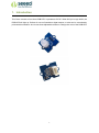
1. Introduction
This Grove consists of one 8mm RGB LED. It operates at 5V DC. When SIG pin is logic HIGH, the
RGB LED will light up. Perfect for use on Seeeduino digital outputs, or also can be controlled by
pulse-width modulation. And it uses three adjustable resistor to change the color of the RGB LED.
2
2. Features
Grove compatible
Color adjustable
Application Ideas
Toys
Decoration
Cautions
Be gentle when adjusting the R, G and B adjustable resistances in case of overturning.
3
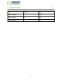
3. Specification
Item
Typical
Unit
Operate Voltage
5.0
VDC
Working Current
20
mA
Variable Resistor
<1
KΩ
4
4. Usage
The three resistances RED, GREEN and BLUE of the module control the R, G and B channels
respectively. By adjusting the three adjustable resistances, it can turn out variable color. The thing
to notice, however, is that be gentle when turning the adjustable resistances.
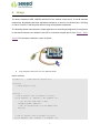
The following sketch demonstrates a simple application of controlling its brightness. As the picture
on the below indicates, the Variable Color LED is connected to digital port 9 of the Grove - Basic
Shield. The hardware installation is gave as follow:
Copy and paste code below to a new Arduino sketch.
Demo code like:
int ledPin = 9;
void setup()
// LED connected to digital pin 9
{
// nothing happens in setup
}
void loop() {
// fade in from min to max in increments of 5 points:
for(int fadeValue = 0 ; fadeValue <= 255; fadeValue +=5) {
// sets the value (range from 0 to 255):
analogWrite(ledPin, fadeValue);
// wait for 30 milliseconds to see the dimming effect
delay(30);
}
// fade out from max to min in increments of 5 points:
for(int fadeValue = 255 ; fadeValue >= 0; fadeValue -=5) {
5
// sets the value (range from 0 to 255):
analogWrite(ledPin, fadeValue);
// wait for 30 milliseconds to see the dimming effect
delay(30);
}
}
Upload the code, please click here if you do not know how to upload.
Adjust the three adjustable resistances, I am sure you will like it. Have a try!
6
5. Resources
Variable Color LED eagle_file
7