1
Training Manual for the Tagisang
Robotics 2014 Technical Training
and Workshop
TRC 2014 Training Manual
May 26-30, 2014
Training Topic Schedule
Day1: Basic Electronics and
CONTENTS
Prototyping
Day1.1: Basic Electronics P.1
Day 2: Gizduino Fundamentals
Day 1.2: Prototyping P.4
Day 3 - 4: Advanced Interfacing
Day 1.3: Electrical Circuit
Day 5: Mini Project
Faults and Troubleshooting
P.7
Day 1.4: Exercises P.8
Day 1.1: Basic Electronics
I. BASIC CONCEPTS - ELECTRICITY
Day2: Gizduino Fundamentals—I. Introduction P.10
When this phenomenon happens in a
controlled environment, it produces the
electricity we encounter and use everyday!
A. Charge
II. Getting Started P.11
Basic unit from which electrical forces
come from.
B. The Law of Conservation of Charge
III. Sketch Fundamentals P.12
IV. Digital Input/Output P.13
V. Analog Input/Output P.14
D. Voltage
Day 3 & 4: Advanced Interfacing—I. Serial Communications P.17
“Charge can neither be created nor destroyed,
II. TRC Pilot Board and Con-
it can only be transferred from one body to
another.”
troller P.18
Potential Difference
The work required to
move a charge from
one point to another
The unit for voltage
is volts
(V = joules/colomb)
III. Communications via Bluetooth P.18
IV. TRC 2013 Vehicle Board
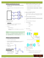
C. Static Electricity
The amount of electrons that jump depends highly on the nature of the material.
If the material loses electrons, it is now
positively charged. If it gains electrons,
it is now negatively charged
P.20
V. Mechatronics: Servo and
DC Motors P.20
When 2 electrically neutral objects are
rubbed against each other, electrons
can jump from one material to another.
TRC 2014 TRAINING MANUAL — Created by ThinkLab exclusively for TRC 2014 only, this document cannot be reproduced or used for purposes other than TRC without prior consent
E. Current
The net flow or
motion of charges
DC – single direction AC – both
direction (back and
forth)
Page 1
Unit for current is amperes :
(A = colomb/sec)
F. Resistance
The ability of any material to
limit the amount of current v
passing through when a potential difference is applied
Unit for resistance is ohms
(Ω = volt/ampere)
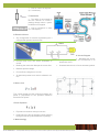
G. Electrical Circuit
Any arrangement of elements representing the 3
concepts that permits current to flow.
K. Circuit Diagram
Current flows once the circuit connection is
closed
Breaking the connection disrupts the current flow
Batteries provide voltage
Current flows, charges turn on bulb
All elements present have various resistance values.
Standard way of illustrating the components and connections in an
electronics circuit
Illustrated with the use of circuit element symbols
H. Ohm’s Law
“The current through an ideal conductor between two
points is proportional to the potential difference
across the two points.”
I. Power Equation
Equivalent to the work done per unit time
Produced by the flow of charges (current) passing
through an electric potential difference (voltage)
J. Water Analogy
TRC 2014 TRAINING MANUAL — Created by ThinkLab exclusively for TRC 2014 only, this document cannot be reproduced or used for purposes other than TRC without prior consent
Page 2
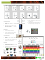
II. COMMON CIRCUIT ELEMENTS AND SYMBOLS
Keeps passage of current to one
direction only
Chemicals inside react differently to
an applied voltage, producing color
A. Voltage Source
Device that supplies a constant
voltage
By virtue of Ohm’s Law, this device also supplies a relative
amount of current
B. Resistor
Current limiting component
Colored bands determine the resistor’s value within a range
C. Potentiometer
Resistors with variable sistance
values
Turning the knob changes the resistance of the component
D. Switch
Component that can open or close
an electrical connection
Changing of state is activated manually (button press)
E.
Light
Emitting
ode
(LED)
Di-
TRC 2014 TRAINING MANUAL — Created by ThinkLab exclusively for TRC 2014 only, this document cannot be reproduced or used for purposes other than TRC without prior consent
Page 3
Day 1.2: Prototyping
II. Breadboard Prototyping
Disconnect the power supply from the breadboard
before putting all the components
Place the actual circuit component onto the breadboard one by one
Always check if you are placing the correct component onto the breadboard
Check connections between the circuit elements
based on the circuit diagram
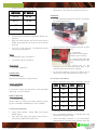
What we will be using
Components (LEDs, Tact Switch, Resistors,
Potentiometers)
9V Battery and battery clip
Digital Multimeter
Breadboard
III. Digital Multimeter
I. Breadboard
A device used to measure/test the following:
Construction base for prototyping electronics
DC Current
Also known as prototyping board or protoboard
DC Voltage
Used to make temporary circuits for testing
AC Voltage
Easy
Resistance
Continuity
LED Tester
to
change
or
replace
connections/
RED Meter Lead
Voltage/Resitance or Amperage (VWmA) port
Positive Connection
TRC 2014 TRAINING MANUAL — Created by ThinkLab exclusively for TRC 2014 only, this document cannot be reproduced or used for purposes other than TRC without prior consent
Page 4
BLACK Meter Lead
Common ground / COM port
Negative Connection
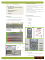
V. LED Test
PROBES
Handles used to hold the tip on the connection
being tested
TIPS
End of the probe, provides the connection
point
IV. Continuity Test
Turn the knob and point the arrow to
the continuity tester position
Connect the tips of the black and red
probes of the multitester, you should hear a an
audible alarm when they are connected
Disconnect power source first before performing
continuity testing
Connect the test leads across the wire / leads you
want to check for continuity
LEDs will work one way only
The longer wire goes to the positive
The negative side is the shorter wire or the LED
with the flat side
Connect the RED meter lead to the positive side of
the LED and the BLACK meter lead to the negative
side of the LED
LED will light up if the LED is working
VI. Resistance Measurement
An audible alarm will be heard if they are connected, if not check the wire or the connection
Do not use the continuity testing for power
sources like batteries or power supplies
Test the tact switch
Turn the knob and point the arrow to
the Resistance Measurement position
Disconnect any power source before
testing
Remove the component from the circuit before testing
Set the dial to the lowest value.
If OL or 1 appears, move to the next level
Connect the test leads across terminals you want
to measure resistance at
WARNING!
Turn the knob and point the arrow to
the LED tester position
Which leads are always connected?
Which leads are connected when you push
the switch?
DO NOT TEST POWER SOURCES!
TRC 2014 TRAINING MANUAL — Created by ThinkLab exclusively for TRC 2014 only, this document cannot be reproduced or used for purposes other than TRC without prior consent
Page 5
Get your potentiometer
Measure resistance from the ff:
1. Both ends of the pot
2. Left end and middle of the pot
3. Right end and middle of the pot
TRY THIS!
•Try turning the potentiometer knob, what happens?
VII. DC Voltage Measurement
Turn the knob and point the arrow to
the DC Voltage Measurement position
Use one value higher than your expected value.
Ex. If you are measuring 9V, set the dial to 20V
Connect the test leads across (in parallel) the terminals you want to measure the voltage at
NOTES:
VIII. DC Current Measurement
Turn the knob and point the arrow to
the DC Current Measurement position
Use one value higher than your expected value.
Ex. If you are measuring 9V, set the dial to 20V
TRC 2014 TRAINING MANUAL — Created by ThinkLab exclusively for TRC 2014 only, this document cannot be reproduced or used for purposes other than TRC without prior consent
Page 6
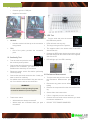
Day 1.3: Electrical Circuit
Faults and Troubleshooting
nent such as a switch
TROUBLESHOOTING:
- use continuity testing to check if
there
are open circuits or
unconnected elements
I. Short Circuit
A low resistance connection established by accident or intention between two points in an electric
circuit
Current tends to flow through the path resistance is
the lowest, bypassing the rest of the circuit
Occurs as a result of improper wiring or broken
insulation
TROUBLESHOOTING:
- use continuity testing to check if
are accidental short circuits
there
TRY THIS!
TRY THIS!
III. Reverse Connection/ Polarity
Current flows only in one direction (DC circuits)
Polarity of a source can be reversed by swapping
the wires on the positive and negative terminal
(+) connects to (-)
(-) connects to (+)
In DC circuits, make sure the polarity is correct
(+) to (+)
LED turns OFF when switch is pushed
II. Open Circuit
An electric circuit in which the normal path of current has been interrupted
Accidental – disconnection of one part of the conducting pathway from another
Intentional – by intervention of an electric compo-
(-) to (-)
TROUBLESHOOTING:
- Make sure that your polarity is
correct before plugging in the
power supply / voltage source
TRC 2014 TRAINING MANUAL — Created by ThinkLab exclusively for TRC 2014 only, this document cannot be reproduced or used for purposes other than TRC without prior consent
Page 7
ALWAYS REMEMBER
TRY THIS!
Check all connections in your circuit before connecting it with the power source
Check for accidental short and open circuits,
loose connections
Connect your voltage supply in the correct
polarity
Verify if the components placed in the circuit are
correct and have correct values
IV. Over Current
A condition when the current in the circuit is larger
than the intended current exists through a conductor
May be caused by a short circuit, loose connection,
excessive load, and incorrect design
TROUBLESHOOTING:
Check also if there are defective components
You do not want this to happen to you
- Check if there accidental short circuits, defective components and incorrect
components / value
DAY 1.4: EXERCISES
EXERCISE 1
Remove one leg of the resistor from the breadboard, what happens?
Place a jumper wire across the LED, what hap-
TRC 2014 TRAINING MANUAL — Created by ThinkLab exclusively for TRC 2014 only, this document cannot be reproduced or used for purposes other than TRC without prior consent
Page 8
DAY 1.4: EXERCISES
Try turning the potentiometer knob to both sides, what happens to #2? How about #3?
Why did the LED at #3 turned off when turning the pot to one side?
Use jumper wires as your switches
What happens to the LED when you remove the wire at A? at B? at C?
Observe the light intensity of the LED in #5 and #6, which one is brighter? Why?
TRC 2014 TRAINING MANUAL — Created by ThinkLab exclusively for TRC 2014 only, this document cannot be reproduced or used for purposes other than TRC without prior consent
Page 9
DAY 2: GIZDUINO
FUNDAMENTALS
Data Acquisition
Toys
Robotics
C. Arduino
I. Introduction
Arduino is an open-source physical computing platform based on a simple microcontroller board, and
a development environment for writing software for
the board.
The Gizduino board, available at E-gizmo, is based
on Arduino Diecimila, a microcontroller board
based on ATMega164/324/644.
Arduino comes with its own open-source Integrated
Development Environment (IDE).
Why Arduino?
A. What is a micronctroller?
Inexpensive
Cross-platform
Simple, clear programming environment
Open-source and extensible software
Open-source and extensible hardware
D. Integrated Development Environment
“One-chip solution”
Highly integrated chip that includes all or most of
the parts needed for a controller:
CPU
RAM
ROM
I/O Ports
Timer
Interrupt Controller
B. Microcontroller Applications
Environmental Monitoring
Automobiles
It connects to the Arduino hardware to upload programs and communicate with them.
Contains:
Toolbar
Text Editor
Status Bar
Console
Menus
TRC 2014 TRAINING MANUAL — Created by ThinkLab exclusively for TRC 2014 only, this document cannot be reproduced or used for purposes other than TRC without prior consent
Page 10
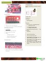
II. Getting Started
Materials needed:
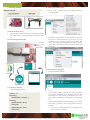
D. Setting up Arduino IDE
A.
Go to Tools -> Board menu and select Gizduino+
w/ ATmega644
Select the serial device of the Arduino board from
the Tools -> Serial Port menu. To find out, you can
disconnect your Arduino board and re-open the
menu; the entry that disappears should be the Arduino board. Reconnect the board and select that
serial port.
Connect Arduino to PC
Connect the Gizduino board to you computer using
the USB Cable. The green power LED should turn
on.
B. Launching Arduino IDE
Double
click
the
Arduino
application
E. Uploading the Program
Save the sketch as Blink
Click “Verify” button to check your code for syntax
errors. After compiling, click “Upload” button in the
environment. If the upload is successful, the message “Done Uploading” will appear in the status
bar.
A few seconds after the upload finishes, you should
see pin13 (L) LED on the board start to blink (in
orange).
C. Creating a sketch
Type the sketch below:
int ledPin = 13;
void setup(){
pinMode(ledPin, OUTPUT); }
void loop(){
digitalWrite(ledPin, HIGH);
delay(1000);
digitalWrite(ledPin, LOW);
delay(1000); }
If it does, congratulations! You’ve gotten Arduino up-and –running!
TRC 2014 TRAINING MANUAL — Created by ThinkLab exclusively for TRC 2014 only, this document cannot be reproduced or used for purposes other than TRC without prior consent
Page 11
III. Sketch Fundamentals
We will now analyze the Blink code that we uploaded
earlier. In this section, we will learn the following:
A. Sketch
where in a sketch.
Special Functions
There are two special functions that are part of
every Arduino sketch:
B. Comments
C. Variables
setup()
A function that is called once, when the
sketch starts.
Setting pin modes or initializing libraries
are placed here
D. Functions
E. Control Structures
A. Sketch
Sketch is the unit of code that is uploaded to and
run on an Arduino board.
Example:
Blink (The sketch uploaded earlier)
B. Comments
Comments are ignored by the Arduino when it runs
the sketch.
It is there for people reading the code: to explain
what the program does, how it works, or why it’s
written the way it is.
For multi-line comment: use /* and */
For single-line comment: use //
Example
Multi-line comment:
Single line comment
C. Variables
Place for storing a piece of data
Variable has a name, a value, and a type.
Example
2. loop()
A function that is called over and over
and is the heart
of most sketches
D. Control Structures
If-Else Statement
Most basic of all programming control
structures.
It allows you to make something happen or
not depending on whether a given condition is true or not.
Loops
While Loop
Do-while Loop
For Loop
Example:
How many times will “Hello” be
displayed?
D. Functions
Also known as procedure or subroutine.
A named piece of code that can be used from else-
TRC 2014 TRAINING MANUAL — Created by ThinkLab exclusively for TRC 2014 only, this document cannot be reproduced or used for purposes other than TRC without prior consent
Page 12
A. ―0‖ and ―1‖
Logic “0”
Logic LOW
Ground (e.g. 0V)
False
Logic “1”
Logic HIGH
Positive (e.g. 5V)
True
B. Setting Pin Mode
EXERCISE: VARYING BLINKING SPEED
Change the value of the delay() to 200.
Did the blinking speed of the LED’s increased or
decreased?
Experiment on the function delay();
Change them to any desired value. Observe what
happens.
pinMode()
Configures the specified pin to behave either as an
input or an output
Syntax:
pinMode(pin, mode)
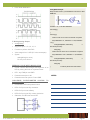
IV. DIGITAL INPUT/OUTPUT
Digital = Discontinuous = Discrete
Gizduino has 24 pins that can be configured as
either digital input or output
pin: the number of the pin whose mode you
wish to set
mode: either INPUT or OUTPUT
C. Setting Pin Output
digitalWrite()
Write a HIGH or LOW value to a digital pin
Syntax:
digitalWrite(pin, value)
pin: pin number
value: HIGH or LOW
TRC 2014 TRAINING MANUAL — Created by ThinkLab exclusively for TRC 2014 only, this document cannot be reproduced or used for purposes other than TRC without prior consent
Page 13
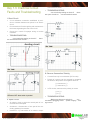
EXERCISE: BLINKING MULTIPLE LEDS
Using the switch connected to pin 7 of Arduino,
make a program that turns ON/OFF the LED.
Setup the circuit below on your breadboard. Modify
your Blink code to turn ON and OFF three LEDs at
the same time.
Button pressed and released = LED ON
Modify your code to turn ON and OFF one LED at
a time
Button pressed and released again = LED OFF
Button pressed and released again = LED ON
And so on…
VI. ANALOG INPUT/OUTPUT
We were able to make our microcontroller talk with
our PC. But the world doesn’t talk digital, only analog.
A. Analog to Digital Conversion
Converts analog voltage signals from the real world
to digital 1’s and 0’s that can be understood by the
PC
D. Reading Pin State
It is like translating a language.
digitalRead()
Analog Signal
Reads the value from a specified digital pin.
Sound
Returns either HIGH or LOW
Temperature
Syntax:
Light
odigitalRead(pin)
pin: the number of the digital pin you want to
read (int)
Digital Signal
1’s and 0’s
EXERCISE: PUSHBUTTON SWITCHING
Setup a simple LED circuit. Use pin 4.
Connect a switch as shown:
Using the switch connected to pin 7 of Arduino,
make a program that turns ON/OFF the LED.
Button pressed =
LED ON
Button not pressed
= LED OFF
B. Analog Input/Output
CHALLENGE: LIGHTS
ON, LIGHTS OFF
Setup a simple LED
circuit and connect
a switch as with the
previous exercise.
Analog = Continuous
Gizduino has
6 (labelled PWM out) analog output pins
8 (labelled A0-A7) analog input pins
TRC 2014 TRAINING MANUAL — Created by ThinkLab exclusively for TRC 2014 only, this document cannot be reproduced or used for purposes other than TRC without prior consent
Page 14
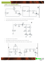
analogRead Example
Connect a potentiometer to the Arduino as shown
below
C. Analog Input
int baud = 9600;
int channel = 0;
void setup() {
Serial.begin(baud);
}
void loop() {
These pins are for input usage only.
You don’t have to set the pinMode for these pins.
float sensorValue = analogRead(channel);
// Read value from pin
Serial.println(sensorValue, DEC);
// Display in decimal format
D. Reading Analog Input
analogRead()
Function to perform 10-bit ADC
Returns value from 0-1023
Syntax:
// Get
delay(1000);
}
Open the Serial Monitor
Channel: ADC channel used
Turn the potentiometer knob
Example: analogRead(0)
What happens to the voltage when the
knob is turned fully clockwise?
What happens to the voltage when the
knob is turned fully clockwise?
What happens to the voltage when the
knob is turned halfway across its full
range?
analogRead(channel)
E. Analog Output
Serial.println(sensorValue*5/1024.0);
the voltage
You don’t have to set the pinMode for these pins
(3, 5, 6, 9, 10, 11) if you are using them as analog
output pins.
TRC 2014 TRAINING MANUAL — Created by ThinkLab exclusively for TRC 2014 only, this document cannot be reproduced or used for purposes other than TRC without prior consent
Page 15
Pulse Width Modulation
analogWrite Example
Setup an LED circuit in your breadboard. Connect it to ANY
PWM PIN.
int ledPin = 15; // OR ANY PWM PIN
void setup() {
}
void loop() {
// fade in from min to max in increments of 5 points:
for(int fadeValue = 0 ; fadeValue <= 255; fadeValue
+=5) {
F. Writing Analog Output
analogWrite()
Supported pins: 3, 5, 6, 9, 10, 11
Function to perform 8-bit DAC
Value ranges from 0-255 (0-5 volts counterpart)
Syntax:
analogWrite(ledPin, fadeValue);
sets value (0 to 255):
//
delay(30); }
// fade out from max to min in increments of 5 points:
for(int fadeValue = 255 ; fadeValue >= 0; fadeValue =5) {
analogWrite(pin, value)
analogWrite(ledPin, fadeValue);
sets value (0 to 255):
Pin: the pin to write to
//
delay(30);
EXERCISE: PULSE WIDTH MODULATION
}
Create a sketch that changes the brightness of an
LED by turning the knob on a potentiometer.
LED - any PWM pin and GND
Potentiometer wiper to A0
Potentiometer outer pins to 5V and GND
CHALLENGE: POTENTIOMETER
BLINKING LEDS
// What is performed in this sketch?
NOTES:
CONTROL
Construct the LED setup shown below
LED1 On if pot is set fully clockwise.
LED2 On if pot is set halfway.
LED3 On if pot is set fully counter clockwise.
Otherwise, all LEDs are turned OFF
TO
TRC 2014 TRAINING MANUAL — Created by ThinkLab exclusively for TRC 2014 only, this document cannot be reproduced or used for purposes other than TRC without prior consent
Page 16
DAY 3 & 4: ADVANCED
INTERFACING
gle quotes, for STRING enclose in double
quotes!
void setup() {
I. Serial Communications
Serial.begin(9600);
How it “talks” with your PC
}
A. USB cable
void loop() {
B. PL2303 chip
Serial.println(“Hello World!”);
C. Serial pins
delay(1000);
}
D.
Poll the Serial line for incoming data
variable = Serial.available();
Returns the number of bytes to be read (int data
type)
IMPORTANT: leave the inside of the parenthesis BLANK!
E. Read the first byte of incoming data
The Gizduino communicates serially
Serial = “one after another”
Stream of 1’s and 0’s
A. UART (Universal
Transmitter
Asynchronous
Receiver/
variable = Serial.read();
Need to store the read data inside a variable (int or
char data type)
IMPORTANT: data is read byte by byte or ONE
CHARACTER PER READ COMMAND, needs
extra processing if expected data are STRINGS
Main communications device employed on the
board
void setup() {
Accompanies the RS232 communications standard, made available to almost all electronic modules with a communications interface
}
Serial.begin(9600);
void loop() {
if (Serial.available() > 0) {
char ReceivedByte = Serial.read();
B. Initialize Serial communications
Serial.begin(<baud>);
Need to do this ONCE, usually first command in
setup();
The value <baud> specifies the baud rate to be
used (e.g. 9600, 38400, 115200, etc)
IMPORTANT: baud rates between communicating devices MUST MATCH!
Serial.print(ReceivedByte);
delay(10);
}
}
NOTES:
C. Pass data to the Serial port
Serial.println(<value>);
Can also use Serial.print();
Able to display any value or data, represented by
<value>
IMPORTANT: for CHAR enclose <value> in sin-
TRC 2014 TRAINING MANUAL — Created by ThinkLab exclusively for TRC 2014 only, this document cannot be reproduced or used for purposes other than TRC without prior consent
II.
Page 17
TRC Pilot Board and Controller
NOTE: Make sure the Serial Monitor baud rate
is set at 38400!
II. Communications via Bluetooth
A. Communications
Wired Medium
Serial/
UART
SPI
I2C
INPUT
ACCESS
Left stick Y-axis
Analog Pin 1
Left stick X-axis
Analog Pin 2
Right stick Y-axis
Analog Pin 3
GSM/
Mobile
Right stick X-axis
Analog Pin 4
WiFi
UP button
Digital Pin 9
ZigBee/RF
BLUETOOTH
LEFT button
Digital Pin 10
DOWN button
Digital Pin 11
RIGHT button
Digital Pin 12
1 button
Digital Pin 5
2 button
Digital Pin 6
3 button
Digital Pin 7
4 button
Digital Pin 8
L1
Digital Pin 3
L2
Digital Pin 4
R1
Analog Pin 5
R2
Digital Pin 2
While docked, upload
sketch to your Gizduino
Open the Serial Monitor to view the outputs
the
Wireless
um
Medi-
B. Bluetooth
Transmits wirelessly at low power (~1 mW)
Distance is limited to 10m radius
Uses spread-spectrum frequency hopping
C. Configuring Bluetooth
Unpower all boards
Set POWER to INT, short MODE pins
pilot_board_debug
TRC 2014 TRAINING MANUAL — Created by ThinkLab exclusively for TRC 2014 only, this document cannot be reproduced or used for purposes other than TRC without prior consent
Page 18
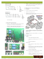
Using jumper wires, connect the following pins:
GIZDUINO
BT SHIELD
Pin 10
RX Pin
Pin 11
TX Pin
+5V
+5V
GND
GND
Upload BTconfig sketch for Bluetooth Shield configuration
Open the Serial Monitor and set the baud rate to
38400, also make sure the return line is set to Both
NL & CR
Type AT on the reply box. The Bluetooth device
should reply and print OK
Open the Serial Monitor to communicate with your
paired device, the connection should be two-way
EXERCISE
Fix the Bluetooth Shield and Gizduino connection
by mounting them like so
Move the Serial Comms switch to the left, as seen
here.
Upload the
BT_BasicControl sample
sketch to your Gizduino
ROLE
for MASTER, type: AT+ROLE=1
for SLAVE, type: AT+ROLE=0
Unplug USB, return the
Serial Comms switch to the
right
Mount one of the
Gizduinos with the Bluetooth Shield back to the
controller and power it with a 9V battery
BAUD RATE
AT+UART=38400,0,0
PAIRING KEY
SLAVE ADDRESS
E. Character Translation
AT+ADDR
If successful, device will reply with a colon-separated
digit string, ex. 2013:3:40964
BIND TO MASTER
AT+BIND=<value>
Where <value> is equal to your slave address, changing ALL COLONS to COMMAS (ex. 2013,3,40964)
D. Deploying Bluetooth
On the other Gizduino, connect an LED on Pin 13
then plug it on the USB connector to power it up
AT+PSWD=xxxx
Where xxxx represents a 4-digit number
Close Serial Monitor, unplug USB, and remove
MODE jumper
Plug again the USB, pairs should connect after a
few seconds (RED LED LIGHTS UP!)
ASCII characters have their equivalent decimal
values
ASCII
Value
ASCII
Value
‘0’
48
‘5’
53
‘1’
49
‘6’
54
‘2’
50
‘7’
55
‘3’
51
‘8’
56
‘4’
52
‘9’
57
Concept used in translating is base counting
Set a terminating character to indicate when the
program will stop processing
While terminating character is not encountered,
assume that the number being passed ends with
TRC 2014 TRAINING MANUAL — Created by ThinkLab exclusively for TRC 2014 only, this document cannot be reproduced or used for purposes other than TRC without prior consent
Page 19
RULE 3 – Always terminate all connections to the
Vehicle Board in the proper polarity (GND goes to
GND, supply goes to supply)
IV. Mechatronics: Servo and DC Motors
A. DC Motor
B. Tricky to connect to microcontrollers!
Needs a lot of power to run
Produces lots of electrical noise that may interfere
with microcontroller pin outputs
Provide separate power source for the DC Motor –
NEVER POWER IT STRAIGHT FROM GIZDUINO
PINS or +5V!
Ensure all ground points (GND) are connected
(common)
the current digit
III. TRC 2013 Vehicle Board
RULE 1 – Never place the Vehicle Board on/near
any metallic or conductive surface/material
RULE 2 – Make sure battery cable connectors are
connected to the battery in proper polarity
B. DC Motor Control
SPEED
Pulse Width Modulation (PWM)
Supported by Gizduino pins 3, 5, 6, 9, 10,
11
Recall: analogWrite();
DIRECTION
Motor Direction follows Source Current
Direction
Needs external circuitry that will reverse
the direction of the current coming from the
motor’s power supply
Direction is binary logic!
Numerous ways to implement this control scheme!
Collective term – DC Motor Driver
H-Bridge configuration is the most commonly used and simplest to build
TRC 2014 TRAINING MANUAL — Created by ThinkLab exclusively for TRC 2014 only, this document cannot be reproduced or used for purposes other than TRC without prior consent
Page 20
Hybrid Driver
SERVO
Red
Brown
Yellow
Electro-mechanical solution for
controlling DC Motor speed and direction
Rugged design allows high current use, with additional safety features such as fused inputs and isolated microcontroller connections
C. Hybrid_RunTest sample sketch
Upload Hybrid_RunTest sample sketch to your
Gizduino
Completely wire the minimum set of connections to
the Vehicle Board. Dock your Gizduino, and turn all
switches ON.
GIZDUINO
+5V
GND
Gizduino Pin
Sketch > ImportLibrary > Servo
E. Servo Motor Control
Create a Servo object
Servo <name>;
Declare Servo presence to Gizduino
Identified by the <name> parameter, give
your Servo a name/label
Attach the servo to a Gizduino pin
<name>.attach(pin);
Bind the Servo to a specific pin on the
Gizduino, pin will provide the rotation data
for the attached Servo
All DIO pins are supported, able to control
multiple Servo motors
Set angle of rotation
<name>.write(angle);
D. Servo Motor
Rotates the shaft based on the specified
value angle, between 0 to 180 only
Position is held until a new value angle is
given,
or
the power to the Servo is reset
Use for loops to count from 0 to 180 and
back
Reconnect your potentiometer and use it to
control your Servo, make Sevo follow the
rotation of the potentiometer knob
Composed of an electric motor mechanically linked
to a potentiometer interfaced with a control chip
Signals are translated into position commands
Servo motors usually
has three wires for power,
ground, and control
Supported by Servo
library for easy interfacing
with
Arduino system
TRC 2014 TRAINING MANUAL — Created by ThinkLab exclusively for TRC 2014 only, this document cannot be reproduced or used for purposes other than TRC without prior consent
Page 21
F. Servo Motor Tips
Power consumption of the Servo is directly proportional to its load, that is, the heavier the load the
more current it draws
All Servos are rated with a Stall Torque value, or
the maximum load it can carry at a given operating
voltage
Displacement of the load increases as it is placed
farther away from the shaft on the Servo arm
CHALLENGE: – SERVO CONTROL VIA BLUETOOTH
}Using the right controller joystick, move the Servo
from 90 to 0 when moving the joystick UP, and
move from 90 to 180 when moving the joystick
DOWN
EXTRA CHALLENGE! – Control TWO Servos by
mapping the other Servo to the left-right movement
of the joystick
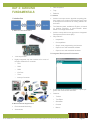
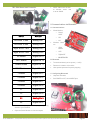
Tagisang Robotics 2014 – Training Kit Parts
List
Gizduino
USB cable connector
Bluetooth Shield
9V rechargeable battery
9V battery charger
Breadboard
Assorted Resistors
Tact Switches
LEDs
Wire Conn Male-Male single
20mm
Wire Conn Male-Male single
40mm
Potentiometer
Servo motor standard
Toolbox
User Manual
1
1
1
2
1
1
30
5
10
20
20
4
2
1
1
NOTES:
TRC 2014 TRAINING MANUAL — Created by ThinkLab exclusively for TRC 2014 only, this document cannot be reproduced or used for purposes other than TRC without prior consent
Page 22