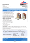
1
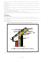
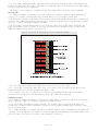
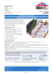
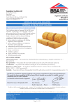
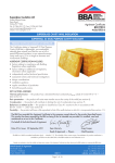
APPROVAL INSPECTION TESTING CERTIFICATION Euroform Products Ltd The Heliport Lyncastle Road Appleton Warrington WA4 4SN Tel: 01925 86099 Fax: 01925 860066 TECHNICAL APPROVALS FOR CONSTRUCTION Agrément Certificate 12/4908 Product Sheet 1 e-mail: [email protected] GEN-X MULTIFOIL INSULATION GEN-X MULTI FOR INSULATED DRY LINING APPLICATIONS PRODUCT SCOPE AND SUMMARY OF CERTIFICATE This Certificate relates to Gen-X Multi for Insulated Dry Lining Applications. The product is applied, in conjunction with an appropriate internal lining board, below rafters in slated or tiled pitched roofs and on masonry walls of new and existing dwellings or buildings of similar occupancy. AGRÉMENT CERTIFICATION INCLUDES: • factors relating to compliance with Building Regulations where applicable • factors relating to additional non-regulatory information where applicable • independently verified technical specification • assessment criteria and technical investigations • design considerations • installation guidance • regular surveillance of production • formal three-yearly review. KEY FACTORS ASSESSED Thermal performance — the product, when combined with other types of insulation, can contribute to meeting the design U value requirement of a wall or roof (see section 5). Condensation risk — the product will contribute to minimising the risk of interstitial and surface condensation. The product does not act as a vapour control layer (see section 6). Durability — the durability of the product is satisfactory and will have a life equivalent to the structure in which it is incorporated (see section 12). The BBA has awarded this Agrément Certificate to the company named above for the product described herein. This product has been assessed by the BBA as being fit for its intended use provided it is installed, used and maintained as set out in this Certificate. On behalf of the British Board of Agrément Date of First issue: 20 May 2012 Sean Moriarty — Head of Approvals Greg Cooper Energy and Ventilation Chief Executive The BBA is a UKAS accredited certification body — Number 113. The schedule of the current scope of accreditation for product certification is available in pdf format via the UKAS link on the BBA website at www.bbacerts.co.uk Readers are advised to check the validity and latest issue number of this Agrément Certificate by either referring to the BBA website or contacting the BBA direct. British Board of Agrément Bucknalls Lane Garston, Watford Herts WD25 9BA ©2012 Page 1 of 12 tel: 01923 665300 fax: 01923 665301 e-mail: [email protected] website: www.bbacerts.co.uk Regulations In the opinion of the BBA, Gen-X Multi for Insulated Dry Lining Applications, if used in accordance with the provisions of this Certificate, will meet or contribute to meeting the relevant requirements of the following Building Regulations: The Building Regulations 2010 (England and Wales) Requirement: C2(c) Resistance to moisture Comment: Requirement: L1(a)(i) Conservation of fuel and power Comment: Requirement: Regulation 7 Materials and workmanship Comment: The product is an acceptable material. See section 12 and the Installation part of this Certificate. The product can contribute to meeting this Requirement. See sections 6.1 and 6.7 of this Certificate. The product can contribute to meeting this requirement. See sections 5.1 and 5.3 of this Certificate. The Building (Scotland) Regulations 2004 (as amended) Regulation: 8(1) Fitness and durability of materials and workmanship Comment: Regulation: Standard: 9 3.15 Building standards — construction Condensation The product is acceptable. See section 12 and the Installation part of this Certificate. The product can contribute to meeting this Standard, with reference to clauses 3.15.1(1), 3.15.4(1) and 3.15.5(1). See sections 6.1 and 6.8 of this Certificate. Comment: Standard: Standard: 6.1(b) 6.2 The product can contribute to meeting clauses or parts of 6.1.1(1) to 6.1.3(1), 6.1.6(1), 6.2.1(1), 6.2.3(1), 6.2.7(1), 6.2.9(1) to 6.2.11(1) and 6.2.13(1) of these Standards. See sections 5.1 and 5.3 of this Certificate. Comment: Standard: 7.1(a)(b) Statement of sustainability The product can contribute to meeting the relevant Requirements of Regulation 9, Standards 1 to 6 and therefore will contribute to a construction meeting a bronze level of sustainability as defined in this Standard. Comment: Regulation: Carbon dioxide emissions Building insulation envelope 12 Building standards — conversions All comments given for this product under Regulation 9, also apply to this Regulation, with reference to clause 0.12.1(1) and Schedule 6(1). Comment: (1) Technical Handbook (Domestic). The Building Regulations (Northern Ireland) 2000 (as amended) Regulation: B2 Fitness of materials and workmanship Comment: Regulation: C5 Condensation Comment: Regulation: Regulation: F2(a)(i) F3(2) Conservation measures Target carbon dioxide Emissions Rate The product is acceptable. See section 12 and the Installation part of this Certificate. The product can contribute to meeting this regulation. See section 6.1 of this Certificate. Comment: The product can contribute to meeting these Regulations. See sections 5.1 and 5.3 of this Certificate. Construction (Design and Management) Regulations 2007 Construction (Design and Management) Regulations (Northern Ireland) 2007 Information in this Certificate may assist the client, CDM co-ordinator, designer and contractors to address their obligations under these Regulations. See section: 2 Delivery and site handling (2.1) of this Certificate. Additional Information NHBC Standards 2011 NHBC accepts the use of Gen-X Multi for Insulated Dry Lining Applications, when installed and used in accordance with this Certificate, in relation to NHBC Standards, Chapter 6.1 External masonry walls and Chapter 7.2 Pitched roofs. General Gen-X Multi for Insulated Dry Lining Applications is for use on the inner side (warm side) of the masonry substrate for wall and under the rafters of a slated or tiled pitched roof built in accordance with BS 5534 : 2003. The product is held in place by timber battens creating an airspace between the product and internal lining. Page 2 of 12 Technical Specification 1 Description 1.1 Gen-X Multi for Insulated Dry Lining Applications consists of two outer layers of reinforced metallised film with a polymer core and three inner layers of polymer fibre wadding separated by two metallised films. The rolls are stitched at the end to keep the seven layers together. 1.2 The nominal characteristics of the product are given in Table 1. Table 1 Product characteristics Number of layers 7 Thickness 30 mm Weight per unit area 678 g·m–2 Width 1.6 m Roll length 10 m 1.3 The product is stapled or nailed into position in accordance with the Certificate holder’s installation procedures. 2 Delivery and site handling 2.1 The product is delivered to site in packs and incorporates a label which includes the BBA Certificate number, product characteristics, recommendations and installation guidelines. 2.2 The product must be protected from prolonged exposure to sunlight and stored either under cover or protected with opaque polyethylene. Where possible, packs should be stored inside, but if stored outside, they should be raised above ground level, so as not to come in contact with ground moisture. 2.3 The product must not be exposed to open flame or other ignition sources. Assessment and Technical Investigations The following is a summary of the assessment and technical investigations carried out on Gen-X for Multi Insulation for Dry Lining Applications, for internal use in both pitched roofs and masonry walls. Design Considerations 3 General 3.1 Care must be taken to ensure that Gen-X Multi for Insulated Dry Lining Applications does not come into contact with heat sources greater than 80°C. Pitched roofs 3.2 Pitched roofs must be tiled or slated and designed and constructed in accordance with BS 5534 : 2003. Masonry walls 3.3 Walls should be structurally sound, designed and constructed in accordance with the following standards: • BS 8110-1 : 1997, BS 8110-2 : 1985, BS EN 1996-1-1 : 2005, BS EN 1996-2 : 2006, BS EN 1996-3 : 2006. 3.4 The installation requires careful detailing around doors and windows to achieve a satisfactory surface for finishing. In addition, the risk of thermal bridging must be minimised at reveals and where heavy separating walls are attached to the external wall. In new work, the construction must be designed to accommodate the thickness of the dry lining, particularly at reveals, heads, sills and in relation to ceiling height. 3.5 Services should be incorporated behind the dry lining, making chasing of the wall unnecessary. 3.6 The surfaces of masonry walls should be sound and free from loose material, any large projections should be removed and holes filled and levelled. A survey of the wall may be required to gauge the extent of any packing that may be required to ensure that the support battens provide a uniform plane for the product to be fixed. 3.7 For both wall and pitched roof applications dry lining boards must be installed in accordance with the relevant sections of BS 8212 : 1995. 4 Practicability of installation The product is designed to be installed by a competent general builder, or a contractor, experienced with this type of product. Page 3 of 12 5 Thermal performance 5.1 Calculations of thermal transmittance (U value) should be carried out in accordance with BS EN ISO 6946 : 2007 and BRE Report (BR 443 : 2006), Conventions for U-value calculations using the following values: • 0.09 — mean emissivity of outer surfaces. • 0.85 m2·KW–1 — mean core thermal resistance [R value of multifoil insulation (nominal thickness 30 mm)], with no air spaces either side. • 0.59(1) m2·KW–1 — resistance for a 20 mm or greater unventilated airspace cavity for horizontal heat flow (wall application)(1). • 0.42(1) m2·KW–1 — resistance of a 20 mm airspace for upwards heat flow (pitched roof application)(1). • 0.00 m2·KW–1 — resistance(2) at zero nominal thickness when compressed between battens and rafters or studs. • 30%/70% — percentage of multifoil thickness in rafter and plasterboard-batten cavities, respectively, for roof applications. • 50%/50% — percentage of multifoil thickness in stud and plasterboard-batten cavities, respectively, for wall applications. • 0%/100% — percentage of multifoil thickness in stud/rafter and plasterboard-batten cavities, respectively, when rafter or stud depth is fully filled with insulation. (1) Unventilated cavity with a width and length at least 10 times the thickness and one high emissivity surface (2) For guidance on U value calculations refer to the BBA Information Bulletin No 3 Reflective foil insulation — Conventions for U value calculations. 5.2 The product must be used in conjunction with additional insulation (see section 14.13 to 14.15) in order to meet the design U values, see section 5.3. The U values (in Table 2 and Table 3) of a roof or wall will depend on the thickness of additional insulation used, the extent and arrangement of timber bridging and the insulating value of other roof/wall components/layers, see Figures 1 and 2. Table 2 U values for example constructions as detailed Construction 200 200 250 200 200 mm mm mm mm mm U value (W·m–2·K–1) rafter rafter rafter rafter rafter with with with with with 110 120 175 135 125 mm mm mm mm mm 0.18 0.18 0.18 0.14 0.14 Phenolic(1) PIR(1) Mineral wool(1) PIR(2) Phenolic(2) (1) Existing roof: rafter, 50 mm width at 400 mm centres. Tiled over a breather membrane, Gen-X Multi insulation placed underside of rafter and 38 mm thick batten. 12.5 mm plasterboard ( = 0.021 W·m–2·K–1) fixed to the battens. Phenolic insulation ( = 0.020 W·m–2·K–1, foil-faced, e = 0.2) or PIR insulation ( = 0.022 W·m–2·K–1, foil-faced, e = 0.2) or Mineral wool ( = 0.037 W·m–2·K–1). (2) New roof: rafter, 47 mm width at 600 mm centres. Tiled over a breather membrane, Gen-X Multi insulation placed underside of rafter and 38 mm thick batten, 12.5 mm plasterboard fixed to the battens. PIR or Phenolic insulation as above. Table 3 U values for example masonry wall (1) constructions as detailed Construction 30 30 60 70 mm mm mm mm Phenolic PIR Phenolic PIR Battens depth (mm) U value (W·m–2·K–1) 38 38 38 38 0.28 0.28 0.19 0.19 (1) Brickwork: 215 mm (bridged with mortar), plasterboard ( = 0.021 W·m–2·K–1) fixed to the 38 mm thick batten at 600 mm centres. Phenolic insulation ( = 0.021 W·m–2·K–1, foil faced, e = 0.2) or PIR insulation ( = 0.022 W·m–2·K–1, foil faced, e = 0.2). Page 4 of 12 Figure 1 Example roof constructions Page 5 of 12 Figure 2 Example wall constructions 5.3 The product can maintain, or contribute to maintaining, the continuity of thermal insulation at junctions between elements and openings. For Accredited Construction Details the corresponding psi values in BRE Information Paper IP1/06 Assessing the effects of thermal bridging at junctions and around openings, Table 3 may be used in carbon emission calculations in Scotland and Northern Ireland. Detailed guidance for other junctions and on limiting heat loss by air infiltration can be found in: England and Wales — Approved Documents to Part L and for new thermal elements to existing buildings, Accredited Construction Details (version 1.0). See also SAP 2009 Appendix K and the iSBEM User Manual for new-build. Scotland — Accredited Construction Details (Scotland) Northern Ireland — Accredited Construction Details (version 1.0). 6 Condensation risk Interstitial condensation 6.1 Pitched roofs or walls incorporating the product will adequately limit the risk of interstitial condensation when designed and constructed in accordance with BS 5250 : 2011, Annexes D, G, H and BS EN ISO 10456 : 2007. 6.2 The risk of interstitial condensation is greatest when the building is drying out after construction. Guidance on preventing condensation from this and other sources is given in BRE Digest 369 Interstitial condensation and fabric degradation and BRE Report (BR 262 : 2002) Thermal insulation: avoiding risks. 6.3 The product has a water vapour resistance in excess of 1000 MN·s·g–1, when tested on a sample free from any stitch. 6.4 When installed in accordance with section 13 and in a continuous layer, the product will provide a high vapour resistant convection-free envelope. 6.5 The use of the product does not preclude the normal precautions against the formation of condensation, especially in rooms expected to have high humidity. Page 6 of 12 6.6 When using this type of product, due consideration must be taken of the overall installation to minimise perforations by services, eg light switches and power outlets and the joints at ceiling and skirting level must be well sealed. Surface condensation 6.7 Pitched roofs or walls will adequately limit the risk of surface condensation when the thermal transmittance (U value) does not exceed 0.35 W·m–2·K–1 for roofs or 0.70 W·m–2·K–1 for walls, at any point, and the junctions with walls are designed in accordance with the relevant requirements of Limiting thermal bridging and air leakage : Robust construction details for dwellings and similar buildings TSO 2002 or BRE Information Paper IP 1/06. 6.8 Pitched roofs or walls will adequately limit the risk of surface condensation when the thermal transmittance (U value) does not exceed 1.2 W·m–2·K–1 at any point. Guidance may be obtained from Annexes G and H of BS 5250 : 2011 and BRE Report (BR 262 : 2002). 7 Behaviour in relation to fire For both wall and pitched roof applications 7.1 The product is classified Class F to EN 13501 : 2007 as no performance was determined. 7.2 The product is determined to be combustible and must be protected from naked flames and other ignition sources during and after installation. 7.3 When installed with an internal dry lining board, eg 12.5 mm thick plasterboard, the product will be contained between the rafters and the dry lining board for pitched roofs, or between the walls and the dry lining for walls, until the board is destroyed. Therefore, the insulation will not contribute to the development stages of a fire. 7.4 When installed with other additional insulation materials, the fire properties of these materials must be taken into consideration. Wall applications 7.5 Construction elements must incorporate cavity barriers at edges, around openings, at junctions with fire-resisting elements in accordance with the relevant provisions of the national Building Regulations. The design and installation of cavity barriers must take into account any anticipated differential movement. 8 Proximity of flues and appliances When the product is installed in close proximity to certain flue pipes and/or heat-producing appliances in buildings subject to national Building Regulations, the relevant provisions and guidance given below should be met: England and Wales — Approved Document J Scotland — Mandatory Standard 3.19, clauses 3.19.1(1) to 3.19.9(1) (1) Technical Handbook (Domestic). Northern Ireland — Technical Booklet L. 9 Air leakage Tests were conducted to BS EN 12114 : 2000 on a sample which included one row of stitch using a range of pressure from 50 Pa to 600 Pa. The net leakage rate was 1.46 m3·hr –1·m–2 at 50 Pa, and the pressure was increased to 3kPa with no visible apparent damage to the sample. 10 Infestation The use of the product as an insulated dry lining for walls or pitched roofs does not in itself promote infestation, but the creation of voids may provide habitation for insects or rodents in areas already infested. Care should be taken to ensure that, wherever possible, all voids are sealed as any infestation may be difficult to eradicate. There is no food value in the materials used. 11 Maintenance Once installed, the product is enclosed by dry lining boards and does not require any maintenance. 12 Durability The product when installed as specified, will have a life equivalent to that of the dry lining board behind which it is incorporated. Installation 13 General 13.1 Installation of Gen-X Multi for Insulated Dry Lining Applications and additional insulation products should be in accordance with the Certificate holder’s instructions and current good building practice. 13.2 The product can be cut by using a cutter. Page 7 of 12 13.3 If an existing vapour control layer is already installed, it must be perforated or removed before installing the product. 13.4 When the product is cut to fit around openings and perimeters, care should be taken to avoid gaps, and any gaps are sealed. 13.5 The product is unrolled across the inside of the timber studs and fixed using nails or staples of at least 14 mm length. 13.6 The product must have overlap joints of at least 50 mm and be taped along the entire length of the joint with reflective tape. 13.7 Care must be taken to ensure the product is not damaged during installation. Should damage occur by tearing or puncture, the damaged area must be taped. 13.8 All exposed edges of the product must be sealed with reflective tape. 13.9 For pitched roofs a vapour control layer must be installed before the plasterboard is fixed onto battens over the product. 14 Procedure Below rafters installation 14.1 Installation starts from the ridge with the product unrolled below the rafters and parallel to the eaves. 14.2 As the product is unrolled it must be kept taut and fixed to the underside of the rafters using staples or nails of at least 14 mm length. 14.3 A minimum of 20 mm airspace between the product and any existing insulation between the rafters must be maintained (see Figure 3). Figure 3 Gen-X Multi under the rafters of a pitched roof with additional insulation 14.4 The next roll must overlap the preceding roll by at least 50 mm (see section 13.6). Page 8 of 12 14.5 The product is permanently fixed in place using 50 mm wide by 38 mm deep wooden counter battens fixed parallel to the rafters with nails or staples. A minimum non-ventilated air space of 15 mm between the product and the inner dry lining boards must be maintained. 14.6 A vapour control membrane is installed below the counter battens before applying the dry lining boards. Masonry walls 14.7 Additional insulation is installed to the inner face of the masonry wall in accordance with the manufacturer’s instructions. The insulation is bridged with studs of minimum dimensions 47 mm wide by 25 mm deep. 14.8 A first layer of vertical wooden battens 50 mm wide by 38 mm deep spaced every 600 mm, is securely fixed to the face of the additional insulation by nailing through to the masonry wall with 75 mm long nails. Care should be taken not to compress or damage the additional insulation. 14.9 The product is unrolled and kept taut across the 50 mm by 38 mm deep wooden battens and fixed to the battens using staples or nails of minimum 14 mm length. A minimum 20 mm air gap between the product and the additional insulation must be maintained (see Figure 4). Figure 4 Gen-X Multi on solid masonry wall with additional insulation 14.10 The next roll must overlap the preceding roll by at least 50 mm (see section 13.6). 14.11 The product is permanently fixed in place using a second layer of 50 mm wide by 38 mm deep wooden battens fixed parallel to the first layer of battens with staples or nails. 14.12 A vapour control layer is installed on the second layer of battens before fixing the dry lining boards. A minimum 20 mm air gap must be maintained between the product and the dry lining board. Additional insulation 14.13 Additional insulation must always be used with the product. Advice on thicknesses required to meet the mean design U values (see Tables 2 to 4) must be sought from the Certificate holder. 14.14 After installing the additional insulation materials, care should be taken to ensure that all air spaces are maintained in accordance with the manufacturer’s instructions for their products and further advice should be sought from the Certificate holder. 14.15 Additional insulation, for example PIR, PUR or mineral fibre products, can be installed between the rafters with a minimum 15 mm air gap above the product. The 15 mm air gap can be maintained by nailing timber battens to the sides of the rafters or using clips in accordance with manufacturer’s instructions. Page 9 of 12 Technical Investigations 15 Tests Results of test data conducted on Gen-X Multi for Insulated Dry Lining Applications were assessed to determine: • emissivity • core R value • air infiltration • tensile strength • tear and puncture strength • resistance to water vapour transmission. 16 Investigations 16.1 An assessment was made of data relating to the thermal insulation properties of the product. 16.2 A visit was carried out to the place of manufacture to assess the production process. 16.3 Installation instructions were examined and U value calculations carried out to investigate the achievability of design U values. Page 10 of 12 Bibliography BS 5250 : 2011 Code of practice for control of condensation in buildings BS 5534 : 2003 Code of practice for slating and tiling (including shingles) BS 7671 : 2008 Requirements for electrical installations. IEE Wiring Regulations. Seventeenth Edition BS 8110-1 : 1997 Structural use of concrete — Code of practice for design and construction BS 8110-2 : 1985 Structural use of concrete — Code of practice for special circumstances BS 8212 : 1995 Code of practice for dry lining and partitioning using gypsum plasterboard BS EN 1996-1-1 : 2005 Eurocode 6 : Design of masonry structures — General rules for reinforced and unreinforced masonry structures BS EN 1996-2 : 2006 Eurocode 6 : Design of masonry structures — Design considerations, selection of materials and execution of masonry BS EN 1996-3 : 2006 Eurocode 6 : Design of masonry structures : Simplified calculation methods for unreinforced masonry structures BS EN 12114 : 2000 Thermal performance of buildings — Air permeability of building components and building elements — Laboratory test method BS EN ISO 6946 : 2007 Building components and building elements — Thermal resistance and thermal transmittance — Calculation method BS EN ISO 10456 : 2000 Building materials and products — Procedures for determining declared and design thermal values EN 13501-1 : 2007 Fire classification of construction products and building elements — Classification using test data from reaction to fire tests Page 11 of 12 Conditions of Certification 17 Conditions 17.1 This Certificate: • relates only to the product/system that is named and described on the front page • is issued only to the company, firm, organisation or person named on the front page — no other company, firm, organisation or person may hold or claim that this Certificate has been issued to them • is valid only within the UK • has to be read, considered and used as a whole document — it may be misleading and will be incomplete to be selective • is copyright of the BBA • is subject to English Law. 17.2 Publications, documents, specifications, legislation, regulations, standards and the like referenced in this Certificate are those that were current and/or deemed relevant by the BBA at the date of issue or reissue of this Certificate. 17.3 This Certificate will remain valid for an unlimited period provided that the product/system and its manufacture and/or fabrication, including all related and relevant parts and processes thereof: • are maintained at or above the levels which have been assessed and found to be satisfactory by the BBA • continue to be checked as and when deemed appropriate by the BBA under arrangements that it will determine • are reviewed by the BBA as and when it considers appropriate. 17.4 The BBA has used due skill, care and diligence in preparing this Certificate, but no warranty is provided. 17.5 In issuing this Certificate, the BBA is not responsible and is excluded from any liability to any company, firm, organisation or person, for any matters arising directly or indirectly from: • the presence or absence of any patent, intellectual property or similar rights subsisting in the product/system or any other product/system • the right of the Certificate holder to manufacture, supply, install, maintain or market the product/system • individual installations of the product/system, including their nature, design, methods, performance, workmanship and maintenance • any works and constructions in which the product/system is installed, including their nature, design, methods, performance, workmanship and maintenance • any loss or damage, including personal injury, howsoever caused by the product/system, including its manufacture, supply, installation, use, maintenance and removal • any claims by the manufacturer relating to CE marking. 17.6 Any information relating to the manufacture, supply, installation, use, maintenance and removal of this product/ system which is contained or referred to in this Certificate is the minimum required to be met when the product/system is manufactured, supplied, installed, used, maintained and removed. It does not purport in any way to restate the requirements of the Health and Safety at Work etc. Act 1974, or of any other statutory, common law or other duty which may exist at the date of issue or reissue of this Certificate; nor is conformity with such information to be taken as satisfying the requirements of the 1974 Act or of any statutory, common law or other duty of care. British Board of Agrément Bucknalls Lane Garston, Watford Herts WD25 9BA ©2012 Page 12 of 12 tel: 01923 665300 fax: 01923 665301 e-mail: [email protected] website: www.bbacerts.co.uk