1
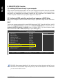
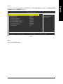
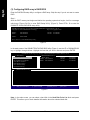
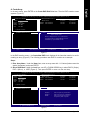
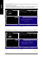
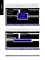
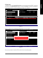
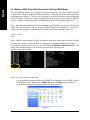
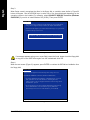
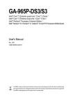
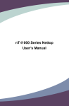
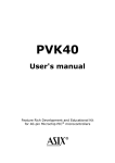
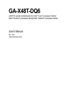
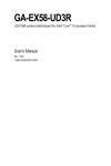
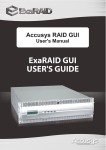
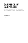
English
4-1-4 Configuring SATA Hard Drive(s)
To configure SATA hard drive(s), follow the steps below:
(1) Install SATA hard drive(s) in your system.
(2) Configure SATA controller mode and boot sequence in BIOS Setup.
(3) Configure RAID set in RAID BIOS.(Note)
(4) Make a floppy disk containing the SATA controller driver.
(5) Install the SATA controller driver during OS installation.
Before you begin
Please prepare:
(a) At least two SATA hard drives (to ensure optimal performance, it is recommended that you use two
hard drives with identical model and capacity). If you do not want to create RAID, you may prepare
only one hard drive.
(b) An empty formatted floppy disk.
(c) Windows XP/2000 setup disk.
(d) Driver CD for your motherboard.
(Note)
Skip this step if you do not want to create RAID array on the SATA controller
- 69 -
Appendix
English
B. GIGABYTE SATA2 Controller
(1) Installing SATA hard drive(s) in your computer
Attach one end of the SATA signal cable to the rear of the SATA hard drive and the other end to available
SATA port(s) on the motherboard. If there are more than one SATA controller on your motherboard, you
may refer to the motherboard user's manual to identify the SATA controller for the connector. Then
connect the power connector from your power supply to the hard drive.
(2) Configuring SATA controller mode and boot sequence in BIOS Setup
Make sure to configure the SATA controller mode correctly in system BIOS Setup and set the first boot
device.
Step 1:
Turn on your computer and press Del to enter BIOS Setup during POST (Power-On Self Test). In BIOS
Setup, go to Integrated Periperals, ensure that the Onboard SATA/IDE Device is enabled. Then set
Onboard SATA/IDE Ctrl Mode to RAID/IDE before configuring RAID. If you do not want to create
RAID, set this item to IDE or AHCI, depending on your need (Figure 1).
CMOS Setup Utility-Copyright (C) 1984-2006 Award Software
Integrated Peripherals
SATA RAID/AHCI Mode
SATA Port0-3
USB Controller
USB 2.0 Controller
USB Keyboard Support
USB Mouse Support
Legacy USB storage detect
Azalia Codec
Onboard H/W 1394
Onboard H/W LAN
SMART LAN
OnBoard LAN Boot ROM
Onboard SATA/IDE Device
Onboard SATA/IDE Ctrl Mode
Onboard Serial Port 1
Onboard Parallel Port
Parallel Port Mode
: Move
Enter: Select
F5: Previous Values
[Disabled]
[Disabled]
[Enabled]
[Enabled]
[Disabled]
[Disabled]
[Enabled]
[Auto]
[Enabled]
[Enabled]
[Press Enter]
[Disabled]
[Enabled]
[RAID/IDE]
[3F8/IRQ4]
[378/IRQ7]
[SPP]
+/-/PU/PD: Value
F10: Save
F6: Fail-Safe Defaults
Item Help
Menu Level
ESC: Exit
F1: General Help
F7: Optimized Defaults
Figure 1
The BIOS Setup menus described in this section may not show the exact settings for your
motherboard. The actual BIOS Setup menu options you will see shall depend on the motherboard
you have and the BIOS version.
GA-965P-DQ6 Motherboard
- 80 -
CMOS Setup Utility-Copyright (C) 1984-2006 Award Software
Advanced BIOS Features
Hard Disk Boot Priority
First Boot Device
Second Boot Device
Third Boot Device
Password Check
CPU Hyper-Threading (Note)
Limit CPUID Max. to 3
No-Execute Memory Protect (Note)
CPU Enhanced Halt (C1E) (Note)
CPU Thermal Monitor 2(TM2) (Note)
CPU EIST Function (Note)
Virtualization Technology (Note)
Init Display First
: Move
F11/12: Profile
[Press Enter]
[CDROM]
[Hard Disk]
[CDROM]
[Setup]
[Enabled]
[Disabled]
[Enabled]
[Enabled]
[Enabled]
[Enabled]
[Enabled]
[PCI]
Item Help
Menu Level
Select Hard Disk Boot
Device Priority
Enter: Select
+/-/PU/PD: Value
F10: Save ESC: Exit
F1: General Help
F5: Previous Values
F6: Fail-Safe Defaults
F7: Optimized Defaults
Figure 2
Step 3:
Save and exit BIOS Setup.
- 81 -
Appendix
English
Step 2:
To boot from Windows installation CD-ROM disk, set First Boot Device under the Advanced BIOS
Features menu to CDROM (Figure 2).
English
(3) Configuring RAID array in RAID BIOS
Enter the RAID BIOS setup utility to configure a RAID array. Skip this step if you do not want to create
RAID.
Step 1:
After the POST memory test begins and before the operating system boot begins, look for a message
which says "Press <Ctrl-G> to enter RAID Setup Utility" (Figure 3). Press CTRL+ G to enter the
GIGABYTE SATA2 RAID BIOS setup utility.
GIGABYTE Technology Corp. PCIE-to-SATAII/IDE RAID Controller BIOS v1.06.23
Copyright (C) 2005 GIGABYTE Technology.
http://www.gigabyte.com
HDD0 :
HDD1 :
ST3120026AS
ST3120026AS
ODD0 :
GO-D1600D
120 GB
120 GB
Non-RAID
Non-RAID
Press <Ctrl-G> to enter RAID Setup Utility ...
Figure 3
In the main screen of the GIGABYTE SATA2 RAID BIOS utility (Figure 4), use the UP or DOWN ARROW
key to highlight through choices. Highlight the item that you wish to execute and press ENTER.
GIGABYTE Technology Corp. PCIE-to-SATAII/IDE RAID Controller BIOS V1.06.23
[ Main Menu ]
[ Hard Disk Drive List ]
Create RAID Disk Drive
Delete RAID Disk Drive
Revert HDD to Non-RAID
Solve Mirror Conflict
Rebuild Mirror Drive
Save And Exit Setup
Exit Without Saving
Mode Name
HDD0: ST3120026AS
HDD1: ST3120026AS
Capacity
120 GB
120 GB
Type/Status
Non-RAID
Non-RAID
[ RAID Disk Drive List ]
[
TAB]-Switch Window
[
]-Select ITEM
[ENTER]-Action
[ESC]-Exit
Figure 4
Note: In the main screen, you can select a hard disk in the Hard Disk Drive List block and press
ENTER. This allows you to check detailed information about the selected hard disk.
GA-965P-DQ6 Motherboard
- 82 -
In the main screen, press ENTER on the Create RAID Disk Drive item. Then the RAID creation screen
appears (Figure 5).
GIGABYTE Technology Corp. PCIE-to-SATAII/IDE RAID Controller BIOS V1.06.23
[ Create New RAID ]
Name:
Level:
Disks:
Block:
Size:
[ Hard Disk Drive List ]
JRAID_
0-Stripe
Select Disk
128 KB
240 GB
Mode Name
HDD0: ST3120026AS
HDD1: ST3120026AS
Available
120 GB
120 GB
Type/Status
Non-RAID
Non-RAID
Confirm Creation
[ Help ]
[ RAID Disk Drive List ]
Enter RAID Name
Enter a string between 1 to 16 characters
in length for the created RAID drive to be
identified by system BIOS or OS.
[
]-Move Cursor
[DEL,BS]-Delete Character
[ENTER]-Next
[ESC]-Abort
Figure 5
In the RAID creation screen, the Create New RAID block displays all the items that need to be set for
creating an array (Figure 5). The following procedure uses RAID 0 creation as an example.
Steps:
1. Enter Array Name: Under the Name item, enter an array name with 1~16 letters (letters cannot be
special characters) and press ENTER.
2. Select RAID Mode: Under the Level item, use UP or DOWN ARROW key to select RAID 0 (Stripe),
RAID 1 (Mirror), or JBOD (Figure 6). Then press ENTER to move onto the next step.
GIGABYTE Technology Corp. PCIE-to-SATAII/IDE RAID Controller BIOS V1.06.23
[ Create New RAID ]
Name:
Level:
Disks:
Block:
Size:
JRAID
0-Stripe
Select Disk
128 KB
240 GB
[ Hard Disk Drive List ]
Mode Name
HDD0: ST3120026AS
HDD1: ST3120026AS
Available
120 GB
120 GB
Type/Status
Non-RAID
Non-RAID
Confirm Creation
[ RAID Disk Drive List ]
[ Help ]
Select RAID Level
RAID 0
RAID 1
JBOD
[
]-Switch RAID Level
[ENTER]-Next
-
Data striped for performance
Data mirrored for redundancy
Data concatenated for huge
temporarily disk required
[ESC]-Abort
Figure 6
- 83 -
Appendix
English
A. Create Array:
English
3. Assign Array Disks: After RAID mode is selected, RAID BIOS automatically assigns the two hard
disks installed as the RAID disks.
4. Set Block Size (only for RAID 0): Under the Block item, use the UP or DOWN ARROW key to
select the block size (Figure 7), ranging from 4K to 128K. Press ENTER when finished.
GIGABYTE Technology Corp. PCIE-to-SATAII/IDE RAID Controller BIOS V1.06.23
[ Create New RAID ]
Name:
Level:
Disks:
Block:
Size:
[ Hard Disk Drive List ]
JRAID
0-Stripe
Select Disk
128 KB
240 GB
Mode Name
HDD0:
ST3120026AS
HDD1:
ST3120026AS
Available
120 GB
120 GB
Type/Status
Non-RAID
Non-RAID
Confirm Creation
[ RAID Disk Drive List ]
[ Help ]
Setting Stripe Block
Select a stripe size which will be used to
divide data from/to seperate RAID members.
The following are typical values:
RAID 0-128KB
[
]-Switch RAID Block Size
[ENTER]-Next
[ESC]-Abort
Figure 7
5. Set Array Size: Under the Size item, type the size of the array (Figure 8), and press ENTER.
GIGABYTE Technology Corp. PCIE-to-SATAII/IDE RAID Controller BIOS V1.06.23
[ Create New RAID ]
Name:
Level:
Disks:
Block:
Size:
[ Hard Disk Drive List ]
Mode Name
HDD0:
ST3120026AS
HDD1:
ST3120026AS
JRAID
0-Stripe
Select Disk
128 KB
240 GB
Available
120 GB
120 GB
Type/Status
Non-RAID
Non-RAID
Confirm Creation
[ RAID Disk Drive List ]
[ Help ]
Setting RAID Capacity
Enter the RAID capacity. The default value
indicates the maximum capacity determined
by the selected members. If less than the
maximum capacity is chosen, the remaining
capacity would be no used.
[
]-Switch Unit
[DEL,BS]-Delete Number
Figure 8
GA-965P-DQ6 Motherboard
- 84 -
[ENTER]-Next
[ESC]-Abort
GIGABYTE Technology Corp. PCIE-to-SATAII/IDE RAID Controller BIOS V1.06.23
[ Create New RAID ]
Name:
Level:
Disks:
Block:
Size:
[ Hard Disk Drive List ]
JRAID
0-Stripe
Select Disk
128 KB
240 GB
Mode Name
HDD0:
ST3120026AS
HDD1:
ST3120026AS
Available
120 GB
120 GB
Type/Status
Non-RAID
Non-RAID
Confirm Creation
[ Help ]
Create RAID on the select HDD(Y/N)?Y
[ RAID Disk Drive List ]
CONFIRM RAID CREATION
ALL DATA ON THE SELECTED HARD DISK
WILL BE LOST WHEN EXIT WITH SAVING
[
]-Switch Unit
[DEL,BS]-Delete Number
[ENTER]-Next
[ESC]-Abort
Figure 9
When finished, the new RAID array will be displayed in the RAID Disk Drive List block (Figure 10).
GIGABYTE Technology Corp. PCIE-to-SATAII/IDE RAID Controller BIOS V1.06.23
[ Main Menu ]
[ Hard Disk Drive List ]
Create RAID Disk Drive
Delete RAID Disk Drive
Revert HDD to Non-RAID
Solve Mirror Conflict
Rebuild Mirror Drive
Save And Exit Setup
Exit Without Saving
Mode Name
HDD0: ST3120026AS
HDD1: ST3120026AS
Capacity Type/Status
120 GB RAID Inside
120 GB RAID Inside
[ RAID Disk Drive List ]
Model Name
RDD0: JRAID
[
TAB]-Switch Window
RAID Level
0-Stripe
[
Capacity Status
240 GB
Normal
]-Select RAID
[ENTER]-Action
Members(HDDx)
01
[ESC]-Exit
Figure 10
- 85 -
Appendix
English
6. Confirm Creation: After all of the items are configured, the selection bar automatically jumps to the
Confirm Creation item. When prompted to confirm your selections (Figure 9), press Y to confirm
or N to abort.
English
To check more detailed information about the array, use the TAB key while in the Main Menu block to
move the selection bar to the RAID Disk Drive List block. Select the array and press ENTER.
A small window displaying the array information will appear in the center of the screen (Figure 11).
GIGABYTE Technology Corp. PCIE-to-SATAII/IDE RAID Controller BIOS V1.06.23
[ Main Menu ]
[ Hard Disk Drive List ]
Create RAID Disk Drive
Delete RAID Disk Drive
Revert HDD to Non-RAID
Solve Mirror Conflict
Rebuild Mirror Drive
Save And Exit Setup
Exit Without Saving
Mode Name
HDD0: ST3120026AS
HDD1: ST3120026AS
[ RAID Information ]
Name:
Level:
Block:
Capacity:
[ RAID Disk Drive List ]
Model Name
RDD0: JRAID
[
TAB]-Switch Window
Capacity Type/Status
120 GB RAID Inside
120 GB RAID Inside
JRAID
0-Stripe
128KB
81GB
RAID Level
Members: HDD 01Capacity Status
0-Stripe
Normal
Status: Normal 240 GB
[
]-Select RAID
[ENTER]-Detail
Members(HDDx)
01
[ESC]-Exit
Figure 11
After configuring the RAID array, select the Save And Exit Setup item in the main screen to save your
settings if you wish to exit the RAID BIOS utility, then press Y (Figure 12).
GIGABYTE Technology Corp. PCIE-to-SATAII/IDE RAID Controller BIOS V1.06.23
[ Main Menu ]
[ Hard Disk Drive List ]
Create RAID Disk Drive
Delete RAID Disk Drive
Revert HDD to Non-RAID
Solve Mirror Conflict
Rebuild Mirror Drive
Save And Exit Setup
Exit Without Saving
[ RAID Disk Drive List ]
Mode Name
HDD0: ST3120026AS
HDD1: ST3120026AS
Save to Disk & Exit (Y/N)?Y
Model Name
RDD0: JRAID
[
TAB]-Switch Window
RAID Level
0-Stripe
[
Capacity Status
240 GB
Normal
]-Select ITEM
[ENTER]-Action
Figure 12
GA-965P-DQ6 Motherboard
Capacity Type/Status
120 GB RAID Inside
120 GB RAID Inside
- 86 -
Members(HDDx)
01
[ESC]-Exit
To delete the array, select Delete RAID Disk Drive in the main menu and press ENTER. The selection
bar will move to the RAID Disk Drive List block. Press the SPACEBAR on the array to be deleted; a
small triangle will appear to mark the selected array (Figure 13). Press Del.
GIGABYTE Technology Corp. PCIE-to-SATAII/IDE RAID Controller BIOS V1.06.23
[ Main Menu ]
Create RAID Disk Drive
Delete RAID Disk Drive
Revert HDD to Non-RAID
Solve Mirror Conflict
Rebuild Mirror Drive
Save And Exit Setup
Exit Without Saving
[ Hard Disk Drive List ]
Mode Name
HDD0: ST3120026AS
HDD1: ST3120026AS
Capacity
120 GB
120 GB
Type/Status
Inside
Inside
[ RAID Disk Drive List ]
Model Name
RDD0: JRAID
[
]-Select RAID
RAID Level
0-Stripe
Capacity Status
240 GB
Normal
[SPACE]-Mark Delete
[DEL]-Confirm
Members(HDDx)
01
[ESC]-Abort
Figure 13
Press Y to confirm yes to the following message (Figure 14) or N to cancel.
GIGABYTE Technology Corp. PCIE-to-SATAII/IDE RAID Controller BIOS V1.06.23
[ Main Menu ]
Create RAID Disk Drive
Delete RAID Disk Drive
Revert HDD to Non-RAID
Solve Mirror Conflict
Rebuild Mirror Drive
Save And Exit Setup
Exit Without Saving
[ RAID Disk Drive List ]
Model Name
RDD0: JRAID
[
]-Select RAID
[ Hard Disk Drive List ]
Mode Name
HDD0: ST3120026AS
HDD1: ST3120026AS
ALL DATA ON THE RAID WILL LOST!!
ARE YOU SURE TO DELETE (Y/N)? N
RAID Level
Capacity Status
0-Stripe
240 GB
Normal
[SPACE]-Mark Delete
[DEL]-Confirm
Capacity
120 GB
120 GB
Type/Status
Inside
Inside
Members(HDDx)
01
[ESC]-Abort
Figure 14
Now, you can proceed to install the SATA controller driver and operating system.
- 87 -
Appendix
English
B. Delete Array:
English
(4) Making a SATA Driver Disk (Required for AHCI and RAID Mode)
To install operating system onto a serial ATA hard disk successfully, you need to install the SATA
controller driver during OS installation. Without the driver, the hard disk may not be recognized during
the Windows setup process. First of all, copy the driver for the SATA controller from the motherboard
driver CD-ROM to a floppy disk. See the instructions below about how to copy the driver in MS-DOS
mode(Note) . Prepare a startup disk that has CD-ROM support and a blank formatted floppy disk.
Step 1: Insert the prepared startup disk and motherboard driver CD-ROM in your system. Boot from the
startup disk. Once at the A:\> prompt, change to the CD-ROM drive (example: D:\>). At the D:\>
prompt, type the following two commands. Press ENTER after each command (Figure 15):
cd bootdrv
menu
Step 2: When the controller menu (Figure 16) appears, remove the startup disk and insert the blank
formatted disk. Select the controller driver by pressing the corresponding letter from the menu.
For example, from the menu in Figure 16, press E to select E) GIGABYTE SATA-RAID Driver. Your
system will then automatically zip and transfer this driver file to the floppy disk.
Press 0 to exit when finished.
Figure 15
(Note)
Figure 16
For users without a startup disk:
Use an alternative system and insert the GIGABYTE motherboard driver CD-ROM. From the
CD-ROM drive folder, double click the MENU.exe file in the BootDrv folder (Figure 17).
A command prompt window will open similar to that in Figure 16.
Figure 17
GA-965P-DQ6 Motherboard
- 88 -
Now that you have prepared the SATA driver disk and configured BIOS settings, you are ready to install
Windows 2000/XP onto your SATA hard drive with the SATA driver. The following is an example of
Windows XP installation.
Step 1: Restart your system to boot from the Windows 2000/XP Setup disk and press F6 as soon as
you see the "Press F6 if you need to install a 3rd party SCSI or RAID driver" message (Figure 18). After
pressing F6, there will be a few moments of some files being loaded before you see the next screen.
Windows Setup
Press F6 if you need to install a third party SCSI or RAID driver.
Figure 18
Step 2:
When a screen similar to that below appears, insert the floppy disk containing the SATA driver and press
S (Figure 19).
Windows Setup
Setup could not determine the type of one or more mass storage devices
installed in your system, or you have chosen to manually specify an adapter.
Currently, Setup will load support for the following mass storage devices(s)
<none>
* To specify additional SCSI adapters, CD-ROM drives, or special
disk controllers for use with Windows, including those for
which you have a device support disk from a mass storage device
manufacturer, press S.
* If you do not have any device support disks from a mass storage
device manufacturer, or do not want to specify additional
mass storage devices for use with Windows, press ENTER.
S=Specify Additional Device ENTER=Continue F3=Exit
Figure 19
- 89 -
Appendix
English
(5) Installing SATA controller driver during OS installation
(Required for AHCI and RAID Mode)
English
Step 3:
When Setup correctly recognizes the driver in the floppy disk, a controller menu similar to Figure 20
below will appear. Use the ARROW keys to select one of the items displayed depending on the
operating system to be installed. For example, select GIGABYTE GBB36X Controller (Windows
2K/XP/2003) if you wish to install Windows XP (32-Bit). Then press ENTER.
Windows Setup
You have chosen to configure a SCSI Adapter for use with Windows,
using a device support disk provided by an adapter manufacturer.
Select the SCSI Adapter you want from the following list, or press ESC
to return to the previous screen.
GIGABYTE GBB36X Controller (Windows 2K/XP/2003)
GIGABYTE GBB36X Controller (Windows XP/2003 64bit)
ENTER=Select F3=Exit
Figure 20
If a message appears saying one or some file(s) cannot be found, please check the floppy disk
or copy the correct SATA driver again from the motherboard driver CD.
Step 4:
When the next screen (Figure 21) appears, press ENTER to continue the SATA driver installation from
the floppy disk.
Windows Setup
Setup will load support for the following mass storage device(s):
GIGABYTE GBB36X Controller (Windows 2K/XP/2003)
* To specify additional SCSI adapters, CD-ROM drives, or special
disk controllers for use with Windows, including those for
which you have a device support disk from a mass storage device
manufacturer, press S.
* If you do not have any device support disks from a mass storage
device manufacturer, or do not want to specify additional
mass storage devices for use with Windows, press ENTER.
S=Specify Additional Device ENTER=Continue F3=Exit
Figure 21
GA-965P-DQ6 Motherboard
- 90 -
WindowsXP Professional Setup
Welcome to Setup.
This port of the Setup program prepares Microsoft(R)
Windows (R) XP to run on your computer.
To set up Windows XP now, press ENTER.
To repair a Windows XP installation using
Recovery Console, press R.
To quit Setup without installing Windows XP, press F3.
Enter= Continue
R=Repair
F3=Exit
Figure 22
- 91 -
Appendix
English
Step 5:
After the SATA controller driver installation is completed, you can proceed with the Windows XP
installation.