1
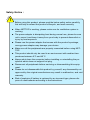
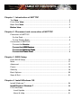
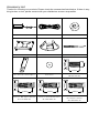
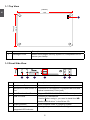
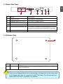
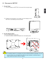
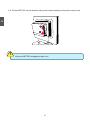
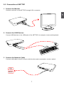
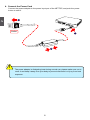
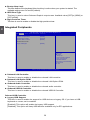
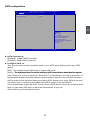
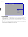
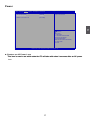
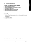
nT-i1000 Series Nettop
User’s Manual
Trademark:
All trademarks are the property of their respective owners.
Version:
User’s Manual V1.0 for nT-i1000 Series Nettop.
P/N: 3A2235F00-000-G
!
ARNING
!
W
CA
UT
IO
N
Symbol description:
Caution : refers to important information that can help you to use NETTOP
better, and tells you how to avoid problems.
Warning: indicating a potential risk of hardware damage or physical injury may
exist.
WEEE:
The use of this symbol indicates that this product may not be treated as household
waste. By ensuring this product is disposed of correctly, you will help prevent potential
negative consequences for the environment and human health, which could otherwise be caused by inappropriate waste handling of this product. For more detailed
information about recycling of this product, please contact your local city office, your
household waste disposal service or the shop where you purchased this product.
CAUTION
RISK OF EXPLOSION IF BATTERY IS REPLACED
BY AN INCORRECT TYPE
DISPOSE OF USED BATTERIES ACCORDING
TO THE INSTRUCTIONS
© All rights reserved.
All trade names are registered trademarks of respective manufacturers listed.
All images are for reference only, please refer to the physical product for specific features.
CA
UT
IO
N
Safety Notice :
!
Before using this product, please read the below safety notice carefully,
this will help to extend the product’s lifecycle, and work normally.
■ When NETTOP is working, please make sure its ventilation system is
working.
■ The power adapter is dissipating heat during normal use, please be sure
not to cover it and keep it away from your body to prevent discomfort or
injury by heat exposure.
■ Please use the power adapter that comes with the product’s package,
wrong power adapter may damage your device.
■ Make sure all the peripherals are properly connected before using NETTOP.
■ This product should only be used in an environment with ambient temperatures between 0◦C and 40◦C.
■ Always shut down the computer before installing or uninstalling the peripheral which does not support hot plug.
■ Disconnect all peripherals before servicing or disassembling this equipment.
■ Please do not disassemble this product by yourself, any disassembly not
approved by the original manufacturer may result in malfunction, and void
warranty.
■ Risk of explosion if battery is replaced by an incorrect type, please dispose of used batteries according to the instructions.
Table of Contents
Chapter 1 Introduction of NETTOP
Top ����
View....................................................................................................2
Front Side ����
View.........................................................................................2
Back Side ����
View.........................................................................................3
............
Bottom View..............................................................................................3
Chapter 2 Placement and connection of NETTOP
Placement of NETTOP
On the Desk..........................................................................................5
On the Display Back..............................................................................5
Connection of NETTOP����
Connect the Monitor..............................................................................7
�������
Connect
������������
the �����������
USB Devices.....................................................................7
Connect
�������������������������
the �������������
Network Cable..................................................................7
Connect
����������������������
the ����������
Power Cord.......................................................................8
Chapter 3 BIOS Setup
Enter BIOS Setup....................................................................................10
Main ....................................................................................................... 11
Advanced................................................................................................13
Power......................................................................................................16
Security...................................................................................................18
Boot Options...........................................................................................20
Save & Exit..............................................................................................21
Chapter 4 Install Windows OS
Install Windows 7....................................................................................24
.
...........................
Install Drivers in Windows 7....................................................................28
.
FOX WinFlash
Local Update.....................................................................................29
About & Help.....................................................................................31
Accessory List
Thanks for choosing our products. Please check the accessories listed below. If there is anything broken or lost, please contact with your distributors as soon as possible.
Power Adapter
Power Cord
Magnet Rubber Foot
Vesa Mount
Seatbase
Opening Tool
3.90mm
8.00mm
9.70mm
Mini PCIe Half Card Support
Screw for Half MiniPCI Card
(M:4.4X2.85mm)(1X)
2.43mm
2.85mm
4.40mm
2.42mm
Screw for HDD Support Bracket
(M:4.7X2.85mm)(4X)
4.40mm
2.92mm
4.70mm
2.85mm
Screw for VESA Mounting
(M8.0X9.7mm)(4X)
Screw Cover
4.85mm
Screw for Half MiniPCI Half
Card Support Bracket
(M:4.4X4.85mm)(1X)
This chapter introduces NETTOP’s outlook :
■
Top View
■
Front Side View
■
Back Side View
■
Bottom View
1-1 Top View
1
(190mm)
7.5in
1
5.3in
(135mm)
No.
1
Name
Description
Kensington Lock
Attach a Kensington security system or a compatible lock to
secure your Nettop
1-2 Front Side View
24mm
1
2
3
4
5
6
No. Name
Description
1
Headphone Port
Connects to a headphone
2
Microphone In and S/PDIF In
Port
Connects to a microphone or playback devices with
optical connectors(3.5mm jack)
3
Multi-Function Card Reader
Support SD/SDHC/MS/MS Pro/MMC memory cards
4
USB 3.0 Ports
Connect to USB devices
Caution:Before using it, you need to install the “����
AS-
Media USB3.0 driver” in the Driver CD.
5
Suspend Button
Enter suspend mode in operating system
6
Power Button with
Integrated LED Indicator
Turning the power on/off, Indicates
�����������������������
system states
1-3 Back Side View
1
1
2
3
4
5
6
No. Name
Description
1
USB 2.0 Ports
Connects to USB devices
2
Display Output Port (VGA)
Connects to display device
3
HDMI Port
Connects to HDMI audio and video
4
Network Port
Standard RJ-45 network port
5
Line Out and S/PDIF Out Port
Connects to powered analog speakers or recording devices with optical connectors(3.5mm jack)
6
Power Input Port
Connects to the power adapter
1-4 Bottom View
1
No.
1
CA
UT
IO
N
!
Name
Description
Sheet Metal
NETDVD(optional accessory) or Magnet-Metal-Feet can magnetize
them to seat firmly
There are four Magnet-Metal-Feet in the package. Just align them to the sheet metal
on the bottom, then they can magnetize the NETTOP easily. The feet can seat and
protect NETTOP when it is placed on the tabletop.
In this chapter, the placement and the connection of some necessary peripherals will be introduced.
This chapter includes the following information:
■
Placement of NETTOP
■Connection of NETTOP
2-1 Placement of NETTOP
1. On the Desk
1.1. You can install your NETTOP in the mount like the right image.
2
1.2. If there is enough space on your desk, you can simply put your NETTOP on the tabletop as shown below.
2. On the Display Back
CA
UT
IO
N
This is the best space-saving way.
2.1. Use four screws to fasten the bracket onto the display back.
!
To install this bracket, your display must follow VESA75/VESA100 standard. The two
groups of holes on your display have different space between, and they help you
easily fasten the bracket onto your display.
2.2. Fit the NETTOP into the bracket with power button locating at the top for easy touch.
2
2
CA
UT
IO
N
1
!
Lift up the NETTOP straightly to take it out.
2-2 Connection of NETTOP
1. Connect the Monitor
Connect a monitor to the NETTOP through VGA connector.
2
2. Connect the USB Devices
Connect USB devices to the USB ports of the NETTOP, for example, mouse and keyboard.
3. Connect the Network Cable
Connect LAN cable to the RJ-45 port, with the other end connected to a hub or switch.
Hub
or
Switch
4. Connect the Power Cord
Connect the power adapter to the power input port of the NETTOP, and push the power
button to start it.
2
1
Outlet
3
CA
UT
IO
N
2
!
The power adapter is dissipating heat during normal use, please make sure not to
cover it and keep it away from your body to prevent discomfort or injury from heat
exposure.
This chapter tells how to change system settings through the
BIOS Setup menus. Detailed descriptions of the BIOS parameters
are also provided.
You have to run the Setup Program when the following cases
occur :
1. An error message appears on the screen during the system
Power On Self Test (POST) process.
2. You want to change the default CMOS settings.
This chapter includes the following information:
■
■
■
■
■
■
■
Enter BIOS Setup
Main
Advanced
Power
Security
Boot Options
Save & Exit
Since BIOS could be updated some other times, the BIOS information described
in this manual is for reference only. We do not guarantee the content of this
manual will remain consistent with the newly released BIOS at any given time in
the future. Please visit our website for updated manual if it is available.
Enter BIOS Setup
CA
UT
IO
N
The BIOS is the communication bridge between hardware and software, correctly setting up the
BIOS parameters is critical to maintain optimal system performance. Power on the computer,
when the message "Press <Del> to enter setup, <F11> Display Boot Menu" appears at the
bottom of the screen, you can press <DEL> key to enter Setup.
!
3
We do not suggest that you change the default values in the BIOS Setup, and we
shall not be responsible for any damage which resulted from the change you made.
Use the arrow right/left keys to select a specific function and go to the submenu. Each function is
explained below:
Main
It displays the basic system configuration, such as CPU Name, memory size, system date,
time and so on. They all can be viewed or set up through this menu.
Advanced
The advanced system features can be set up through this menu.
Power
All the items related with Green function features can be setup through this menu.
Security
The Administrator/User password can be set up through this menu to prevent unauthorized
use of your computer. If you set a password, the system will ask you to key in correct
password before boot or access to Setup.
Boot Options
Boot features can be set up through this menu. You can set the boot device priority and enable
"Quiet Boot" feature here.
Save&Exit
The optimal performance settings can be loaded through this menu. However, it may offer
better performance in some ways (such as less I/O cards, less memory ...etc.), still, it may
cause problem if you have more memory or I/O cards installed. It means, if your system
loading is heavy, set to optimal default may sometimes come out an unstable system. What
you need now is to adjust BIOS setting one by one, trial and error, to find out the best setting
for your current system. You also can save or discard the changes and exit BIOS setup here.
10
Main Menu
The BIOS Setup is accessed by pressing the <Del> button after the Power-On Self-Test (POST)
memory test begins and before the operating system boot begins. Once you enter the BIOS Setup Utility, the Main Menu will appear on the screen. The Main Menu provides System Overview
information and allows you to set the System Time and Date. Use the “←” and “→” cursor keys to
navigate between menu screens.
Aptio Setup Utility - Copyright (C) 2011 American Megatrends, Inc.
Main Advanced Power Security BootOptions Save & Exit
Processor
Genuine Intel (R) CPU
@
Core Frequency
2.13 GHz
Count
2�
System Memory
System Memory Size�������
2048 MB
MAC Address
Onboard RTL8111F LAN
� System Date
System Time
Access Level
00-E0-4C-69-00-01
[Mon 11/07/2011]
[15:35:35]
Administrator
Set the Date. Use tab to
switch between Date elements.
→ ←: Select Screen
↑ ↓: Select Item
Enter: Select
+/-: Change Opt
F7: Load User-defined Defaulta
F8: Save as User-defined
F9: Optimized Defaults
(When Access Level is Administator)
F10: Save & Exit
ESC: Exit
Version 2.13.1216. Copyright (C) 2002-2011 Foxconn, Inc.
System BIOS
► Project Version
It displays the current BIOS version. User can check this information and discuss with the field
service people if a BIOS upgrade is needed.
► Build Date
This item shows the BIOS building date.
► EC Version
It displays the current EC version.
Processor
► Genuine Intel (R) CPU
This item shows the current CPU name.
► Core Frequency
It shows the core frequency of the processor.
► Count
It shows the total number of cores.
System Memory
►System Memory Size
11
3
System BIOS
�������������������������������������������������������������������������������
Version
B34F1D05
project
Build Date 09/29/2011
EC Version
12.F1.01
3
This item displays the current memory size. The size is depending on how many memory modules were installed in your system before powering on.
► MAC Address
This item shows the onboard LAN MAC address.
► System Date
<weekday><month><date> <year> format.
Day—weekday from Sun. to Sat., this message is automatically displayed by BIOS (Read
Only).
Month—month from 1 to 12.
Date—date from 1 to 31.
Year—year, set up by users.
Use [ENTER], [TAB] or [SHIFT-TAB] to select a field. Use [+] or [-] to input the value.
► System Time
This item allows you to configure the desired time. Use [ENTER], [TAB] or [SHIFT-TAB] to
select a field. Use [+] or [-] to input the value.
The three fields of the setting are <hour> : <minute> : <second> respectively.
► Access Level
It displays your current access level. If you enter system with a user password, it will dispaly
“User”. If no password is set or you enter system with administrator password, this item will
dispaly “Administrator”.
12
Advanced
Aptio Setup Utility - Copyright (C) 2011 American Megatrends, Inc.
Main Advanced Power Security BootOptions Save & Exit
▶ Miscellaneous
▶ Integrated Periperals
▶ SATA configuration
Miscellaneous
3
→ ←: Select Screen
↑ ↓: Select Item
Enter: Select
+/-: Change Opt
F7: Load User-defined Defaulta
F8: Save as User-defined
F9: Optimized Defaults
(When Access Level is Administator)
F10: Save & Exit
ESC: Exit
Version 2.13.1216. Copyright (C) 2002-2011 Foxconn, Inc.
► Miscellaneous/Integrated Periperals/SATA configuration
Press<Enter>to go to relative submenu.
Miscellaneous
Aptio Setup Utility - Copyright (C) 2011 American Megatrends, Inc.
Main Advanced Power Security BootOptions Save & Exit
Bootup Num-Lock
Intel IGD Configuration
IGFX-Boot Type
High Precision Event Timer Configuration
High Precision Timer
[off]
Select the keyboard NumLock state
[CRT+HDMI]
[Enabled]
→ ←: Select Screen
↑ ↓: Select Item
Enter: Select
+/-: Change Opt
F7: Load User-defined Defaulta
F8: Save as User-defined
F9: Optimized Defaults
(When Access Level is Administator)
F10: Save & Exit
ESC: Exit
Version 2.13.1216. Copyright (C) 2002-2011 Foxconn, Inc.
13
3
► Bootup Num-Lock
This item defines if the keyboard Num Lock key is active when your system is started. The
available settings are: On and Off (default).
► IGFX-Boot Type
This item is used to select Onboard Graphic output sreen. Available value:[CRT]or [HDMI] or [CRT+HDMI].
► High Precision Timer
This item is used to enable or disable the high precision timer.
Integrated Peripherals
Aptio Setup Utility - Copyright (C) 2011 American Megatrends, Inc.
Main Advanced Power Security BootOptions Save & Exit
Onboard LAN Controller
Onboard LAN Option ROM
Onboard Audio Controller
Onboard USB3.0 Controller
Onboard USB Controller
Legacy USB Support
[Enabled]
[Disabled]
[HD Audio]
[Enabled]
Enable/Disable Onboard LAN Controller.
[Enabled]
→ ←: Select Screen
↑ ↓: Select Item
Enter: Select
+/-: Change Opt
F7: Load User-defined Defaulta
F8: Save as User-defined
F9: Optimized Defaults
(When Access Level is Administator)
F10: Save & Exit
ESC: Exit
Version 2.13.1216. Copyright (C) 2002-2011 Foxconn, Inc.
► Onboard LAN Controller
This item is used to enable or disable the onboard LAN controller.
► Onboard LAN Option ROM
This item is used to enable or disable the onboard LAN Option ROM.
►Onboard Audio Controller
This item is used to enable or disable the onboard audio controller.
►Onboard USB3.0 Controller
This item is used to enable or disable the onboard USB3.0 Controller.
Onboard USB Controller
►Legacy USB Support
This item is used to enable the support for USB devices on legacy OS. If you have a USB keyboard or mouse, set to enabled.
[Enabled]: This option will enable the legacy USB support.
[Disabled]: This option will keep USB devices available only for EFI applications.
14
SATA configuration
Aptio
AptioSetup
SetupUtility Utility -- C
Copyright
opyright(C)
(C)2011
2011American
AmericanMegatrends,
Megatrends,Inc.
Inc.
Main
Main Advanced
Advanced Power
Power Security
Security BootOptions
BootOptions Save
Save&&Exit
Exit
SATA Controller(s)
SATA Controller(s)
Configure SATA as
Configure SATA as
[Enabled]
[Enabled]
[AHCI]
[AHCI]
Enable/Disable
Enable/DisableSATA
SATADevice.
Device.
3
→ → ←
←::Select
SelectScreen
Screen
↑ ↑ ↓↓::Select
SelectItem
Item
Enter:
Enter:Select
Select
+/-:
+/-:Change
ChangeOpt
Opt
F7:
F7:Load
LoadUser-defined
User-definedDefaulta
Defaulta
F8:
F8:Save
Saveas
asUser-defined
User-defined
F9:
F9:Optimized
OptimizedDefaults
Defaults
(When
(WhenAccess
AccessLevel
LevelisisAdministator)
Administator)
F10:
F10:Save
Save&&Exit
Exit
ESC:
ESC:Exit
Exit
Version
Version2.13.1216.
2.13.1216.Copyright
Copyright(C)
(C)2002-2011
2002-2011Foxconn,
Foxconn,Inc.
Inc.
► SATA Controller(s)
[Disabled] : Disable SATA Controller.
[Enabled] : Enable SATA Controller.
► Configure SATA as
This item is used to set the operation mode of your SATA ports. Setting values are: [IDE];
[AHCI].
[IDE] - This configures the SATA ports to support IDE mode.
[AHCI] -��������������������
The Advanced Host Controller
����������������������������������������������������������������
Interface (AHCI) specification describes the register
level interface for a Host Controller for Serial ATA. The specification includes a description of
the hardware/software interface between system software and the host controller hardware.
AHCI provides more advanced features including SATA features, but some SATA drives may
not support AHCI, unless they are labeled with AHCI support in its specification.
If your motherboard supporting AHCI, and you have a SATA device, which also supports AHCI,
then you can select IDE option to have fair performance, or you can
select AHCI to get its best performance.
15
Power
Aptio Setup Utility - Copyright (C) 2011 American Megatrends, Inc.
Main Advanced Power
Power Security BootOptions Save & Exit
[S3(STR)]
[Enabled]
3
ACPI Suspend Mode Deep Sleep Support
Select the highest ACPI sleep state the
system will enter when the SUSPEND
button is pressed.
→ ←: Select Screen
↑ ↓: Select Item
Enter: Select
+/-: Change Opt
F7: Load User-defined Defaulta
F8: Save as User-defined
F9: Optimized Defaults
(When Access Level is Administator)
F10: Save & Exit
ESC: Exit
Version 2.13.1216. Copyright (C) 2002-2011 Foxconn, Inc.
► ACPI Suspend Mode
This item is used to set the energy saving mode of the ACPI function. When you select “S1 (POS)” mode, the power is always on and computer can be resumed at any time. When you select “S3 (STR)” mode, the power will be down after a period of time. The status of the computer before it entering STR will be saved in memory, and the computer can quickly return to previous state when the STR function wakes.
► Deep Sleep Support
This item is used to enable or disable Deep Sleep Support function.When entering deep sleep
mode system(S4/S5) only can wake up from power button.
16
Power
Aptio Setup Utility - Copyright (C) 2011 American Megatrends, Inc.
Main Advanced Power
Power Security BootOptions Save & Exit
ACPI Suspend Mode Deep Sleep Support
Restore on AC Power Loss
[S3(STR)]
[Disabled]
[Last State]
Deep Power Off Mode
Version 2.13.1216. Copyright (C) 2002-2011 Foxconn, Inc.
► Restore on AC Power Loss
����������������������������������������������������������������������������������������������
This item is used to set which state the PC will take with when it resumes after an AC power loss.
17
3
→ ←: Select Screen
↑ ↓: Select Item
Enter: Select
+/-: Change Opt
F7: Load User-defined Defaulta
F8: Save as User-defined
F9: Optimized Defaults
(When Access Level is Administator)
F10: Save & Exit
ESC: Exit
Security
Aptio Setup Utility - Copyright (C) 2011 American Megatrends, Inc.
Main ���������������������������������������������������������������������������������
Advanced Power Security
Security BootOptions Save & Exit������������������������
Administrator Password Status
User Password Status
Change Supervisor Password
BIOS Write Protect
Not Installed
Not Installed
[Enabled]
Valid Keys:
(1)a-z (A-Z)
(2)0~9
(3)11 special keys:-=[];,./
(2)key pad:0-9 support and 5 special
keys
3
→ ←: Select Screen
↑ ↓: Select Item
Enter: Select
+/-: Change Opt
F7: Load User-defined Defaulta
F8: Save as User-defined
F9: Optimized Defaults
(When Access Level is Administator)
F10: Save & Exit
ESC: Exit
Version 2.13.1216. Copyright (C) �����������������������
2002-2011 Foxconn, Inc.
► Administrator Password Status
Create New Password
This item is used to install or change administrator password.
After you input administrator password, it then will ask you to confirm the password.when the
password has been set up , the following interface will be displayed.
Create New Password
► User Password Status
This item is used to install or change user password.
► Change Supervisor Password
This item is used to install or change supervisor password
► BIOS Write Protect
To protect the system BIOS, there is a BIOS write-protection mechanism provided to prevent
BIOS FLASH tool being improperly used to update BIOS.
18
Security
Aptio Setup Utility - Copyright (C) 2011 American Megatrends, Inc.
Main ���������������������������������������������������������
Advanced Power Security
Security BootOptions Save & Exit
Administrator Password Status
User Password Status
Installed
Not Installed
Change Supervisor Password
Change User Password
Security option
[Setup]
BIOS Write Protect
[Enabled]
Valid Keys:
(1)a-z (A-Z)
(2)0~9
(3)11 special keys:-=[];,./
(2)key pad:0-9 support and 5 special
keys
3
→ ←: Select Screen
↑ ↓: Select Item
Enter: Select
+/-: Change Opt
F7: Load User-defined Defaulta
F8: Save as User-defined
F9: Optimized Defaults
(When Access Level is Administator)
F10: Save & Exit
ESC: Exit
Version 2.13.1216. Copyright (C) �����������������������
2002-2011 Foxconn, Inc.
►Change User Password
This item is used to install or change user password.
►Security option
To protect the BIOS from being changed by the unauthorized users, there is a security option provided for your choice.
[setup]: A password will be required to enter the CMOS Setup.
[system]: A password will be required to enter both the system and CMOS Setup.
19
Boot Options
Aptio Setup Utility - Copyright (C) 2011 American Megatrends, Inc.
Main Advanced
������������������������������������������������������������������������������
Power Security BootOptions Save & Exit����������������������
3
Set Boot Priority
1st Boot
2nd Boot 3rd Boot
4th Boot
[Optical Disk:WDC...]
[Hard Disk]
[Removable]
[Network]
Set Boot Priority.
▶Hard Disk Drive BBS Priorities
▶Optical Disk Drive BBS Priorities
▶Removable Device BBS Priorities
▶NETWORK Device BBS Priorities
Quiet Boot
[Disabled]
→ ←: Select Screen
↑ ↓: Select Item
Enter: Select
+/-: Change Opt
F7: Load User-defined Defaulta
F8: Save as User-defined
F9: Optimized Defaults
(When Access Level is Administator)
F10: Save & Exit
ESC: Exit
Version 2.13.1216. Copyright (C) �����������������������
2002-2011 Foxconn, Inc.
► 1st/2nd/3rd/4th Boot
These items are used to set the system boot order.
► Hard Disk Drives BBS Priorities
Press <Enter> to go to its submenu. This option is used to specify the boot priority sequence
from available hard disk drives.
► Optical Disk Drive BBS Priorities
Press <Enter> to go to its submenu.This option is used to specify the boot priority sequence
from available Optical disk drives.
►Removable Device BBS Priorities
Press <Enter> to go to its submenu.This option is used to specify the boot priority sequence
from available Removable Device.
►NETWORK Device BBS Priorities
Press <Enter> to go to its submenu.This option is used to specify the boot priority sequence
from available NETWORK Device.
► Quiet Boot
This item is used to enable/disable the quiet boot.
[Disabled] : Displays the normal POST messages.
[Enabled] : Displays OEM customer logo instead of POST messages.
20
Save & Exit
Aptio Setup Utility - Copyright (C) 2011 American Megatrends, Inc.
������������������������������������������������������������������
Main ���������������������������������������������������������
Advanced Power Security BootOptions Save
Save &
& Exit�
Exit
Exit system setup after saving
the changes.
Save Changes and Exit
Discard Changes and Exit
Save Changes
Discard Changes
Load Default Values
Save as User Default Values
Load User Default Values
3
→ ←: Select Screen
↑ ↓: Select Item
Enter: Select
+/-: Change Opt
F7: Load User-defined Defaulta
F8: Save as User-defined
F9: Optimized Defaults
(When Access Level is Administator)
F10: Save & Exit
ESC: Exit
Version 2.13.1216. Copyright (C) 2002-2011 Foxconn, Inc.
► Save Changes and Exit
If you select this option and press <Enter>, a message will be displayed in the screen.
Select [Yes] to save your changes and exit, select [No] or <ESC> to return to the main menu.
► Discard Changes and Exit
If you select this option and press <Enter>, a message will be displayed in the screen.
Select [Yes] to exit setup utility without saving your modifications, select [No] or <ESC> to
return to the main menu.
► Save Changes
If you select this option and press <Enter>, a message will be displayed in the center of the
screen. Select [Yes] to save your changes, select [No] or <ESC> to return to the main menu.
► Discard Changes
If you select this option and press <Enter>, a message will be displayed in the center of the
screen. Select [Yes] to discard your modifications, select [No] or <ESC> to return to the main
menu.
► Load Default Values
Optimal defaults are the best settings of this motherboard.
Always load the Optimal defaults after updating the BIOS or after clearing the CMOS values.
Select this option and press Enter, it will pop out a dialogue box to let you load the defaults.
Select <Yes> and then press <Enter> to load the defaults. Select <No> and press <Enter>, it
will not load.
By this default, BIOS have set the optimal performance parameters of system to improve the
performances of system components. But if the optimal performance parameters to be set
cannot be supported by your hardware devices (for example, too many expansion cards were
installed), the system might fail to work.
21
► Save as User Default Values
If you select this option and press <Enter>, a message will be displayed in the screen.
Select [Yes] to save the changes done so far as user defaults, select [No] or <ESC> to return
to the main menu.
► Load User Default Values
3
If you select this option and press <Enter>, a message will be displayed in the screen.
Select [Yes] to restore/load the user defaults to all the setup options, select [No] or <ESC> to
return to the main menu.
22
This chapter introduces the following information:
■
Install Windows 7
■
Install Drivers in Windows 7
■
FOX WinFlash
Make sure you have these ready :
1. NETDVD. (It is an optional accessory. If there is no NETDVD in this package, you need other
purchase an external USB DVD-ROM drive.)
2. NETTOP driver CD. (In this package)
3. Windows 7 Install CD. (Other purchase)
Before we continue :
■ Your NETTOP power is off.
■ Connect the NETDVD or USB DVD-ROM drive.
4
Install Windows 7
1. Push power button to turn on your computer, then press <Del> key to enter BIOS Setup.
2. Put the Windows 7 Install CD into the NETDVD or USB DVD-ROM drive.
3. Select and go to the “BootOptions” menu, set the “1st Boot” to “Optical Disk”, press <F10>
key to save change and exit BIOS.
Aptio Setup Utility - Copyright (C) 2011 American Megatrends, Inc.
Main ������������������������������������������������������������������������������
Advanced Power Security BootOptions Save & Exit����������������������
Set Boot Priority
1st Boot
2nd Boot 3rd Boot
4th Boot
[Optical Disk:WDC...]
[Hard Disk]
[Removable]
[Network]
Set Boot Priority.
▶Hard Disk Drive BBS Priorities
▶Optical Disk Drive BBS Priorities
▶Removable Device BBS Priorities
▶NETWORK Device BBS Priorities
Quiet Boot
[Disabled]
→ ←: Select Screen
↑ ↓: Select Item
Enter: Select
+/-: Change Opt
F7: Load User-defined Defaulta
F8: Save as User-defined
F9: Optimized Defaults
(When Access Level is Administator)
F10: Save & Exit
ESC: Exit
Version 2.13.1216. Copyright (C) �����������������������
2002-2011 Foxconn, Inc.
4. The computer will reboot, and it will start loading files for installing Windows 7 Operating
System.
5. After that, it will start Windows and come out a “Install Windows” dialog box to set the “Lan-
guage to install”, “Time and current format” and “ Keyboard or input method”. Click “Next” to continue and click “Install now” button to start the setup.
6. When the license terms appear, select to accept and click “Next” to continue.
24
7. It then asks you to select the installation type. Click “Custom (advanced)” to install a new copy of Windows.
4
8. Later the setup will display the hard disk partitions of your system. If there were other systems (such as Linux) installed previously, you need select them and click “Drive options (advanced)” to delete them. When all partitions are clean, setup will display the biggest size of your hard drive.
25
4
9. In this biggest hard disk size screen, you can click “New” button to create partitions as you need. In this example, we will create a 70GB partition to install Windows, and click “Apply”.
To ensure that all Windows features work correctly, Windows might create an additional partitions for system files, so you will see a system reserved partition. Select the 70GB partition
and click “Next” to continue.
26
10. From this step we start to install windows 7 into your hard disk, including copying Windows files, expanding Windows files...etc. During the installation, your computer will restart sev
eral times.
4
11. When the installation is completed, setup will prepare your compute for the first use. Then
you can follow steps to select system settings, create an account, set a password...etc,
until the whole process is completed and enter Windows 7 operating system.
27
Install Drivers in Windows 7
4
1. When the Windows 7 is completely installed, you have to install the necessary drivers before
using the NETTOP. Take out the Windows 7 Install CD from the USB DVD-ROM drive, and
put the driver CD inside.
2. Waiting for a few seconds, the main menu will be displayed, click “Driver” to enter the Driver
menu shown as below:
3. Use these options to install all the drivers for your system. You must click "Intel Chipset Driver"
to install it first. After that, you can click "One Click Setup" to install all the other drivers, or you
can click on each individual driver to install it manually.
4. After all the drivers are installed, you need to restart your NETTOP, then you can start using it.
28
FOX WinFlash
FOX WinFlash is a useful utility to backup and update your system BIOS.
CA
UT
IO
N
Supporting Operating Systems :
■
Windows 7 (32-bit)
!
Please set the BIOS setting “BIOS Write Protect” or “Super BIOS Protect” to [Disabled] when running this application.
4
Using FOX WinFlash:
1. Local Update
1-1 Local Update - BIOS Information
This page lets you know your system BIOS information.
Minimum
Exit
Show current
BIOS information
Toolbar
Note: BIOS Size 16Mb = 16M bit = 2M Byte
Please refer to the physical motherboard for detail.
29
1-2 Local Update - Backup
This page can back up your system BIOS. You can click “Backup BIOS”, and keyin a file name,
then click“Save” to finish the backup operation. The extension of this backup file is “.ROM” for
AMI BIOS. Make sure you can remember the file name together with the directory which it is
stored, prevented that you may need them to recover your BIOS later.
4
Key in a BIOS name
Click here
1-3 Local Update - Update
This page helps you to update your BIOS from a local file. After click “Update BIOS”, An alert
message will be displayed to ensure if you really want to continue, click “Yes” to confirm. A setup
wizard will guide you to load a local BIOS file to finish the operation. You must remember from
which directory to load your new BIOS file (with an extension of “.ROM” for AMI BIOS) before the
setup wizard starts.
30
2. About & Help
This page shows some information about FOX WinFlash.
Show information about
FOX WinFlash
4
31
Statement:
This device complies with part 15 of the FCC Rules. Operation is subject to the following two
conditions: (1) This device may not cause harmful interference, and (2) this device must accept
any interference received, including interference that may cause undesired operation.
Warning:
FEDERAL COMMUNICATIONS COMMISSION INTERFERENCE STATEMENT
This equipment has been tested and found to comply with the limits for a Class B digital device,
pursuant to part 15 of the FCC Rules. These limits are designed to provide reasonable protection
against harmful interference in a residential installation. This equipment generates, uses and can
radiate radio frequency energy and, if not installed and used in accordance with the instructions,
may cause harmful interference to radio communications. However, there is no guarantee
that interference will not occur in a particular installation. If this equipment does cause harmful
interference to radio or television reception, which can be determined by turning the equipment off
and on, the user is encouraged to try to correct the interference by one or more of the following
measures:
▪ Reorient or relocate the receiving antenna.
▪ �����������������������������������������������������������
Increase the separation between the equipment and receiver.
▪ ��������������������������������������������������������������������������������������������
Connect the equipment into an outlet on a circuit different from that to which the receiver
is connected.
▪ �������������������������������������������������������������������
Consult the dealer or an experienced radio/ TV technician for help.
Caution:
Any changes or modifications not expressly approved by the grantee of this device could
void the user’s authority to operate the equipment.
RF exposure warning:
This equipment must be installed and operated in accordance with provided instructions and the
antenna(s) used for this transmitter must be installed to provide a separation distance of at least 20
cm from all persons and must not be co-located or operating in conjunction with any other antenna
or transmitter. End-users and installers must be provide with antenna installation instructions and
transmitter operating conditions for satisfying RF exposure compliance.
Warning statement for Europe:
Also, put in the manual which directive to fulfil and also which countries to sell the product.
Example of a text to tell which directive has been fulfilled:
Hereby, Foxconn, declares that this nT-i1000 Series is in compliance with the essential requirements
and other relevant provisions of Directive 1999/5/EC.”