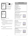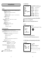
1
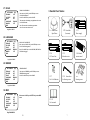
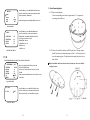
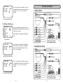
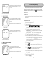
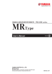
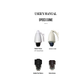
USER’S MANUAL SPEED DOME V07121-LM Outdoor Series Outdoor Series (360° Continuous Rotation) Vandal Proof Series Indoor Series 2 Thanks for your purchase of our product. In order to make good use of this product, please read this user’s manual carefully. In order to use this product correctly and safely; be familiar with all operation steps. Please keep this user’s manual for future reference. This document contains proprietary information, which is protected by copyright. The information contained in this document is subject to changes without notice. SAFETY WARNING Before using this product, please read installation instructions carefully and remove the protective lining from the dome before proceeding with set up. In case of failure, disconnect power or remove power supply before contact our service personnel. To avoid electric shocks, do not disassemble this product on your own. Be sure to ask a skilled technician for the job. Use enclosed power supply only. Do not use other type of power supply, or the product may be damaged or fire can be triggered. Keep unconnected wires, plugs, duly insulated, or they might cause short circuit and damage this product. Do NOT connect power to the unit until all installation steps are completed. Do not turn the camera lens with your hand, doing so might damage camera. Do not point this camera to the sun or a shining object, do not put it on a static object; doing so might damage the camera. To avoid damage, do not load this camera in a place subject to vibration, humidity or a dusty environment. 3 Table of Contents Safety warning 30.7 AF MODE 3 MASK C MASK D POSITION AF MODE TRACKING Instructions 1. Accessories Move cursor to AF MODE, press ENTER key to enter AF MISC [2/2] MODE menu. OFF →TRC AF AUTO2 1.1 Indoor Series 6 1.2 Vandal Proof Series 7 MISC [2/2] MENU 1.3 Outdoor Series 8 30.8 TRACKING MODE 1.4 Outdoor Series (360° Continuous Rotation) 9 2. Installation 2.1 Indoor Series 10 2.2 Vandal Proof Series 13 2.3 Outdoor Series 14 2.4 Outdoor Series (360° Continuous Rotation) 16 MISC [2/2] MASK C MASK D POSITION AF MODE TRACKING Press UP or DOWN key to select TRC AF/FULL AF. TRC AF: AF range is 1m~∞. FULL AF: AF range is Min. Object Distance~∞. Move cursor to TRACKING MODE, press ENTER key to enter TRACKING MODE menu. OFF TRC AF →AUTO1 Press UP or DOWN key to select AUTO1/AUTO2/FIX. AUTO1: AF when zoom ratio is x1~x23. AUTO2: AF when zoom ratio is x6~x23. MISC [2/2] MENU 3. Cable Connection When you select FIX., and press ENTER key to enter TRACKING LEVEL menu. TRACK LEVEL 3.1 Indoor Series 19 3.2 Vandal Proof Series 19 Press UP or DOWN key to select TRACK LEVEL. 3.3 Outdoor Series 20 The AF start position as below: 000: ∞. 3.4 Outdoor Series (360° Continuous Rotation) 20 128: 3m. 3.5 Wire specification 21 TRACK LEVEL 000 255: 1m. MISC [2/2] MENU 4. Infrared Remote Control 22 5. Initial Programming 5.2 Camera ID setup 23 5.3 Load Default 23 5.4 OSD MENU FUNCTION SETUP 24 5.4.1 GROUP (Auto Pan, Group Auto Cruise, Recorded Cruise) 24 5.4.1.1 AUTOPAN 25 5.4.1.2 GROUP1 ~ GROUP5 25 4 61 30.5 MASK A / B / C / D MISC [1/2] H-REVERS V-REVERS POSI/NEGA PRIORITY →MASK A MASK B OFF OFF POSI AGC 5.4.1.3 CRUISE MASKING AREA SETTING Move cursor to MASK A/B, press ENTER key to enter MASK A/B menu. MISC [1/2] MENU MISC [2/2] →MASK C MASK D POSITION AF MODE TRACKING Move cursor to MASK C/D, press ENTER key to enter MASK C/D menu. OFF TRC AF AUTO2 →032 064 048 032 26 5.4.3 MASK 27 5.4.4 AUTO TRACKING 28 5.4.5 PROTOCOL 29 5.4.6 ID 29 5.4.7 MISC (Manual control speed setup, Auto Flip, Default) 29 Operation 6. Infrared remote control mode 31 Then press ENTER key to enter MASK A/B/C/D SETTING 6.2 Remote control 31 menu. 6.3 Alarm and Output On / Off 31 6.4 Preset Positions CALL, SAVE and CLEAR 32 6.5 Recall Preset Positions 32 V-SIZE press ENTER key to enter NUMBER SETTING 6.6 Auto Pan Mode and Group Auto Cruise Mode 32 menu. Press UP or DOWN key to adjust number. 6.7 Speed activate Auto Tracking Function 32 Move cursor to H-POSITION, V-POSITION, H-SIZE or H-POSITION V-POSITION H-SIZE V-SIZE 5.4.2 ALARM (Alarm Mode Setup) 6.1 Select Camera - By Input camera ID Press UP or DOWN key to select ON/OFF. MISC [2/2] MENU MASK A/B/C/D 25 The ranges of parameters as below: H-POSITION: -80~+80 V-POSITION: -60~+60 7. RS-485 Control mode H-SIZE: 0~+80 7.3 Controls 33 V-SIZE: 0~+60 7.4 Protecting 33 MASK A/B/C/D SETING MENU Remarks 30.6 DEFAULT POSITION MISC [2/2] MASK C MASK D →POSITION AF MODE TRACKING 8. Maintenance & cleaning 34 9. Troubleshooting 35 POSITION menu. 10. Specifications 36 Press UP or DOWN key to select position No. (1~64) or OFF. 11. Optional accessories 37 12. Lens internal setting 39 Default Position when camera power on. Move cursor to POSITION, press ENTER key to enter OFF TRC AF AUTO2 MISC [2/2] MENU 60 5 30.1 H-REVERS 1-Accessories MISC [1/2] Please check if the accessories enclosed are completed. If there is any shortage, please contact your local dealer and replace a new one. 1.1 Indoor Series →OFF OFF POSI AGC H-REVERS V-REVERS POSI/NEGA PRIORITY MASK A MASK B Horizontal Reverse (Mirror) Function Move cursor to H-REVERS, press ENTER key to enter FREEZE ON/OFF menu. Press UP or DOWN key to select ON/OFF. MISC [1/2] MENU 30.2 V-REVERS MISC [1/2] 1.1.3 Power supply MISC 0 (In camera) OFF →OFF POSI AGC Vertical Reverse (Up-side Down) Function Move cursor to V-REVERS, press ENTER key to enter FREEZE ON/OFF menu. Press UP or DOWN key to select ON/OFF. [1/2] MENU AUTO TILT PA N/ 7 4 1 8 5 2 9 6 3 1.1.2 Control line AR K50 3 1.1.1 Indoor Speed Dome H-REVERS V-REVERS POSI/NEGA PRIORITY MASK A MASK B 1.1.4 AC Power Line 1.1.5 1.1.6 Infrared Infrared receiver remote control 30.3 POSI/NEGA MISC [1/2] H-REVERS V-REVERS POSI/NEGA PRIORITY MASK A MASK B OFF OFF →POSI AGC Positive or Negative Picture Function Move cursor to POSI/NEGA, press ENTER key to enter POSI/NEGA menu. Press UP or DOWN key to select POSI/NEGA. MISC [1/2] MENU 1.1.7 1.1.8 1.1.9 No. 4 AAA Batteries Securing screws User’s manual 30.4 PRIORITY MISC [1/2] H-REVERS V-REVERS POSI/NEGA PRIORITY MASK A MASK B OFF OFF POSI →AGC Selecting IR SW INT Detecting Signal Move cursor to PRIORITY, press ENTER key to enter PRIORITY menu. Press UP or DOWN key to select AGC/SENSE UP. MISC [1/2] MENU 6 59 27. SCALE ZOOM SCALE DISPLAY SETUP MENU [5/5] ZOOM+AF AF SLEEP →SCALE LANGUAGE WINKER MISC OFF OFF OFF ENGLISH OFF Move cursor to SCALE, press ENTER key to enter 1.2 Vandal Proof Series SCALE ON/OFF menu. Press UP or DOWN key to select ON/OFF. The zoom scale will be display on right-down of the screen in SCALE ON mode. Note: The zoom scale is non-linear approximate value. It’s a reference value for user. Page5 MAIN MENU 1.2.1 Vandal Proof 1.2.2 Control line Speed Dome (In camera) 1.2.3 Power supply 28. LANGUAGE 3 4 PA N/ 7 TILT LANGUAGE selecting menu. AUTO 8 5 2 9 6 Move cursor to LANGUAGE, press ENTER key to enter 0 OSD LANGUAGE SELECT AR K50 3 [5/5] OFF OFF OFF ENGLISH OFF 1 SETUP MENU ZOOM+AF AF SLEEP SCALE →LANGUAGE WINKER MISC Press UP or DOWN key to select ENGLISH, DEUTSCH or ITALIANO language. 1.2.4 1.2.5 AC Power Line Infrared receiver 1.2.6 Infrared remote control 1.2.7 1.2.8 Screw driver 1.2.9 No. 4 AAA Batteries for Securing screws Securing screws Page5 MAIN MENU 29. WINKER SETUP MENU ZOOM+AF AF SLEEP SCALE LANGUAGE →WINKER MISC [5/5] OFF OFF OFF ENGLISH OFF WINKER SELECT Move cursor to WINKER, press ENTER key to enter WINKER selecting menu. Press UP or DOWN key to select ON/OFF. Page5 MAIN MENU 30. MISC SETUP MENU ZOOM+AF AF SLEEP SCALE LANGUAGE WINKER →MISC [5/5] OFF OFF OFF ENGLISH OFF Move cursor to MISC, press ENTER key to enter MISC menu. 1.2.10 User’s manual Page5 MAIN MENU 58 7 23. FOCUS SPEED 1.3 Outdoor Series SETUP MENU DEFAULT FREEZE FREEZE MODE ZOOM SPEED FOCUS SPEED GAMMA 1.3.1 Outdoor Speed Dome 1.3.2 Control line (In camera) [4/5] CANCEL OFF FIELD MAX →MIN GAMMA1 Power supply FOCUS SPEED SELECTING menu, then Press UP or DOWN key to select MIN, +1, +2, +3, MAX (5 steps adjustable). 24. GAMMA 0 3 PA N/ TILT 4 7 AUTO 8 5 2 9 6 AR K50 3 1 AC Power Line 1.3.5 Infrared receiver Move cursor to set FOCUS SPEED, press ENTER key to Page4 MAIN MENU 1.3.3 SETUP MENU 1.3.4 FOCUS SPEED ADJUSTMENT 1.3.6 Infrared remote control DEFAULT FREEZE FREEZE MODE ZOOM SPEED FOCUS SPEED GAMMA [4/5] CANCEL OFF FIELD MAX MIN →GAMMA1 GAMMA SELECT Move cursor to set GAMMA menu, press ENTER key to select GAMMA mode , then Press UP or DOWN key to select GAMMA1 or GAMMA2. GAMMA1 = 0.45 GAMMA2 = 1.0 Page4 MAIN MENU 25. ZOOM + AF SETUP MENU 1.3.7 No. 4 AAA Batteries 1.3.8 Screw driver for Securing screws 1.3.9 Securing screws →ZOOM+AF AF SLEEP SCALE LANGUAGE WINKER MISC [5/5] OFF OFF OFF ENGLISH OFF ZOOM TRIGGER AUTO FOCUS Move cursor to set ZOOM+AF mode, press ENTER key into select ZOOM+AF menu. Press UP or DOWN key to select ON/OFF. Page5 MAIN MENU 26. AF SLEEP SETUP MENU 1.3.10 Wall-mount Bracket 1.3.11 Ceiling mount Bracket 1.3.12 User’s manual ZOOM+AF →AF SLEEP SCALE LANGUAGE WINKER MISC [5/5] OFF OFF OFF ENGLISH OFF AUTO FOCUS SLEEP Move cursor to AF SLEEP, press ENTER key to enter AF SLEEP ON/OFF menu. Press UP or DOWN key to select ON/OFF. The image change less than auto focus range in five minutes; the auto focus will sleep in AF SLEEP ON mode. If the image change more ±6dB than auto focus range, the auto focus will wake up. Page5 MAIN MENU 8 57 19. DEFAULT 1.4 Outdoor Series (360° Continuous Rotation) SETUP MENU [4/5] →CANCEL OFF FIELD MAX MIN GAMMA1 DEFAULT FREEZE FREEZE MODE ZOOM SPEED FOCUS SPEED GAMMA RESTART THE CAMERA AND RESET PARAMETERS TO FACTORY’S DEFAULT. Move cursor to DEFAULT, press ENTER key to enter DEFAULT CANCEL/OK menu. Press UP or DOWN key to select OK, then press ENTER key. Page4 MAIN MENU 1.4.1 Outdoor Speed Dome 1.4.2 Control line 1.4.3 1.4.4 1.4.5 Infrared receiver 1.4.6 Infrared remote control 1.4.7 No. 4 AAA Batteries 1.4.8 Stable Lid 1.4.9 Spacer (Transparent) 1.4.10 Spacer (White) 1.4.11 Wall-mount Bracket 1.4.12 Spacer (White) 1.4.13 U Shape Spanner 1.4.14 User’s manual Power supply 3 6 9 2 CANCEL →OFF FIELD MAX MIN ON/OFF menu. AC Power Line Press UP or DOWN key to select ON/OFF. ILT 4 Move cursor to FREEZE, press ENTER key to enter FREEZE PAN/T DEFAULT FREEZE FREEZE MODE ZOOM SPEED FOCUS SPEED GAMMA GAMMA1 AU TO 8 5 FREEZE PICTURE FUNCTION 7 [4/5] 1 SETUP MENU 0 ARK- 503 20. FREEZE Page4 MAIN MENU 21. FREEZE MODE SETUP MENU DEFAULT FREEZE FREEZE MODE ZOOM SPEED FOCUS SPEED GAMMA [4/5] CANCEL OFF →FIELD MAX MIN GAMMA1 FREEZE FIELD (or FRAME) OF PICTURE FUNCTION Move cursor to FREEZE MODE, press ENTER key to select FREEZE MODE menu. Press UP or DOWN key to select FIELD/FRAME. Page4 MAIN MENU 22. ZOOM SPEED SETUP MENU DEFAULT FREEZE FREEZE MODE ZOOM SPEED FOCUS SPEED GAMMA [4/5] CANCEL OFF FIELD →MAX MIN GAMMA1 ZOOM SPEED ADJUSTMENT Move cursor to ZOOM SPEED, press ENTER key to enter ZOOM SPEED SELECTING menu, then Press UP or DOWN key to select MAX, +3, +2, +1, MIN adjustable). (5 steps Page4 MAIN MENU 56 9 2-Installation IR INT LEVEL →MAX IR INT LEVEL 2.1 Indoor Series Press ENTER key to enter IR INT LEVEL ADJUSTMENT menu. Press UP or DOWN key to select IR INT LEVEL MIN, +1, +2, +3, +4, +5, +6, +7, +8, +9, +11, +12, +13, +14, +15, +16, MAX, 2.1.1 Names of parts 18 steps adjustable. A. Mounting plate IR INT LEVEL MENU B. Top line outlet C. Side line outlet (2 Outlet) *1 *2 *3 OFF x2 x4 x6 x8 x 12 x 16 x 32 x 64 D. Base BASE x x MAX 16 15 14 13 11 9 E. Dome cover +1 x MAX 15 14 13 12 11 9 7 +2 x 16 14 13 12 11 10 8 6 +3 x 15 13 12 11 10 9 7 5 +4 MAX 14 12 11 10 9 8 6 4 +5 16 13 11 10 9 8 7 5 3 +6 15 12 10 9 8 7 6 4 2 +7 14 11 9 8 7 6 5 3 1 MAX 13 10 8 7 6 5 4 2 MIN F. Mounting hole (4 Hole) G. Mounting slot for Flush mount bracket (3 Hole) 2.1.2 Remove protective lining 2.1.2.1 Turn the dome cover clockwise to open it and carefully remove protective lining 2.1.2.2 Place the dome cover back and turn tightly (counterclockwise). IR INT LEVEL TABLE NOTE1: *1: AGC LEVEL *2:IR INT LEVEL (ACT UP THE LEVEL) *3:SENSE UP NOTE2: IR INT LEVEL (MAX) Approach 15Lux (illumination) IR INT LEVEL (MIN) Approach 0.02Lux (illumination) ※ Do not touch the lens with your hands or other object ※ Do not turn the lens or remove other parts; doing so may cause damage. 18. INITIAL 2.1.3 Basic setup 2.1.3.1 Please refer to 3.1 Cable Connection and 3.5 Cable specification: connect Power line, Video cable, Infrared receiver insulation cable first,then connect Alarm cable and RS-485 PVC instrument cable (pair type) if needed。 2.1.3.2 Load batteries into infrared remote control and use infrared remote control to setup camera ID and RS-485 control protocol. Please refer to 4 Infrared Remote control and 5 Initial Programming. 10 SETUP MENU POSITION H-GAIN V-GAIN MOTION IR INITIAL [3/5] LOAD. +6 +6 ON. AUTO. →ON LENS RESET FUNCTION Move cursor to INITIAL, press ENTER key to enter INITIAL ON/OFF menu. Press UP or DOWN key to select ON/OFF. When you select ON, the lens will initial again. Page3 MAIN MENU 55 2.1.4 Install mounting plate Press ENTER key to enter MOTION FUNCTION menu. MOTION Press UP or DOWN key to select motion detection AREA, →AREA LEVEL TIME OSD LEVEL (Sensitivity), TIME, OSD. +4 30sec OFF 2.1.4.1 Remove mounting plate Please turn mounting plate clockwise approximately 15° to separate the mounting plate and the base When detecting motion, it will display MOT on the screen. MOTION MENU Press ENTER key to enter MOTION AREA menu. AREA Press UP or DOWN key to select motion detection H-POSITION 00 H-POSITION, V-POSITION, H-SIZE and V-SIZE. V-POSITION H-SIZE V-SIZE 00 65 44 The ranges of parameters as below: H-POSITION: -80~+80 V-POSITION: -60~+60 H-SIZE: 0~+80 V-SIZE: 0~+60 MOTION AREA MENU 17. IR IR FILTER REMOVABLE FUNTION (DAY & NIGHT FUNCTION) SETUP MENU POSITION H-GAIN V-GAIN MOTION IR INITIAL [3/5] LOAD. +6 +6 ON. →AUTO. ON Move cursor to IR, press ENTER key to enter IR AUTO/DAY/NIGHT menu. 2.1.4.2 Please select suitable location to install IP Speed dome. The long aperture should face backward of monitoring scope and take 1.1.8-Securing Screws to secure the mounting plate. (The dimensions of mounting hole please refer to figure below). ※ Before installation, make sure the structure of location you choose can hold the weight of camera. You can press UP or DOWN key to select AUTO / DAY /NIGHT. When you select DAY/NIGHT mode, camera will fix on Color or BW mode. Page3 MAIN MENU IR IR SW SW Press ENTER key to enter IR SW FUNCTION menu. →INT. Press UP or DOWN key to select IR SW detection INT. IR SW can detect INT. (AGC and SENSE UP) signal. IR SW INT. MENU 54 11 2.1.5 Combine mounting plate with Speed Dome Long aperture of mounting plate aim to point K (middle of two wire outlet) Turn Speed Dome clockwise approximately 15°, long aperture will meet wire outlet L. 14 H-GAIN This is used to enhance the compensation of the picture quality. H-GAIN: Horizontal Compensation Make sure speed combine with mounting plate tightly. (Refer to figure below). SETUP MENU POSITION H-GAIN V-GAIN MOTION IR INITIAL [3/5] LOAD. →+6 +6 OFF AUTO ON Move cursor to H-GAIN, press ENTER key to enter H-GAIN ADJUSTMENT menu. Press UP or DOWN key to select MIN, +1, +2, +3, +4, +5, +6, +7, +8, +9, +11, MAX, 13 steps adjustable. Page3 MAIN MENU Diagram of finished installation 15. V-GAIN This is used to enhance the compensation of the picture quality. V-GAIN: Vertical Compensation SETUP MENU 2.1.6 Other way to install Speed Dome Flush Mount (Bracket is optional) Wall mount (Bracket is optional) POSITION H-GAIN V-GAIN MOTION IR INITIAL [3/5] LOAD. +6 →+6 OFF AUTO. ON Move cursor to V-GAIN, press ENTER key to enter V-GAIN ADJUSTMENT menu. Press UP or DOWN key to select MIN, +1, +2, +3, +4, +5, +6, +7, +8, +9, +11, MAX, 13 steps adjustable. Page3 MAIN MENU 16. MOTION MOTION DETECTION FUNCTION SETUP MENU 2.1.7 When finished all above steps, please connect the control connecting line to related facilities. (Refer to 3 Cable Connections, Indoor Series) Please make sure all POSITION H-GAIN V-GAIN MOTION IR INITIAL [3/5] LOAD. +6 +6 →ON. AUTO. ON Move cursor to MOTION, press ENTER key to enter MOTION ON/OFF menu. Press UP or DOWN key to select ON. installation steps are correct then connect power. Page3 MAIN MENU ※ Keep unconnected wires, plugs, duly insulated, or they may cause short circuit and damage this product. 12 53 2.2 Vandal Proof Series POSITION LOAD Press ENTER key to enter POSITION LOAD SELECTNG →1 POSITION LOAD menu. Press UP or DOWN key to select position (1 to 64 position that you want to LOAD), then press ENTER key that will be loaded. POSITION LOAD MENU ALARM POSITION ALARM POSITION DELAY TIME →OFF OFF Press ENTER key to enter ALARM POSITION SELECTNG menu. Press UP or DOWN key to select alarm position (OFF, 1 to 64 position that you want to set), then press ENTER key that will be set. When input alarm signal, alarm position will be loaded. ALARM POSITION MENU ALARM POSITION ALARM POSITION OFF DELAY TIME →OFF Press ENTER key to enter ALARM POSITION SELECTNG menu. Press UP or DOWN key to select alarm delay time (OFF, 1 ~ 2.2.1 Names of parts A. Dome cover B. Base C. Mounting hole D. Securing screw E. Waterproof joint (Do not open) F. Waterproof ring 2.2.2. Remove protective lining 2.2.2.1 Use screwdriver (accessory 1.2.8) turns counterclockwise to remove all securing screws. 2.2.2.2 Remove dome cover and waterproof ring. 2.2.2.3 Remove protective lining. 2.2.2.4 Load waterproof ring and dome cover back and tighten securing screws (turn clockwise). ※ ※ ※ ※ Do not touch lens with your hands or other objects. Do not turn the lens or remove other parts. Doing so may cause damage. Do not scratch the dome cover or touch any parts. Make sure all the screws are properly tightened to keep Vandal speed dome waterproof. 60 sec. that you want to set), then press ENTER key that will be set. ALARM POSITION MENU POSITION OSD OSD POSITION →OFF R-U Display position number. OSD set ON, position number will be display on right-up(R-U) or right-down(R-D) of the screen. 2.2.3 Basic setup 2.2.3.1 Please refer to 3.1 Cable Connection and 3.5 Cable specification: connect Power line, Video cable, Infrared receiver insulation cable first,then connect Alarm cable and RS-485 PVC instrument cable (pair type) if needed. 2.2.3.2 Load batteries into infrared remote control and use infrared remote control to setup camera ID and RS-485 control protocol. Please refer to 4 Infrared Remote control and 5 Initial Programming. 2.2.4 Install Speed Dome Use securing screws (accessory 1.2.9) install speed dome in an appropriate position. Before installation, make sure the structure of location you choose can hold the weight of camera. (2.4Kg) POSITION OSD MENU ※ Keep unconnected wires, plugs, duly insulated, or they may cause short circuit and damage this product. 52 13 2.3 Outdoor Series FOCUS Press UP or DOWN key to select FOCUS FAR to NEAR. 2.3.1 Names of parts A. Outer layer of base B. Base C. Cover D. Wall mounted Bracket E. Wire sheathing F. Securing screws for wire sheathing FAR ----------- NEAR FOCUS ADJUSTMENT MENU 12. AUTO FOCUS SETUP MENU 2.3.2 Remove protective lining. 2.3.2.1 Turn counterclockwise and carefully remove the protective lining. WHITE BAL SYNC ZOOM DIGITAL P/T/Z FOCUS AUTO FOCUS [2/5] AWB. OFF Move cursor to AUTO FOCUS, press ENTER key to enter AUTO FOCUS FUNCTION SELECTING menu. Press UP or DOWN key to select AUTO FOCUS ON or OFF. →ON Page2 MAIN MENU 13. POSITION 2.3.2.2 Remove securing screw for shipment (M4 *10mm) by turning counterclockwise (As mark below). ※ Warning: Securing screw for shipment must be properly tightened before shipping this product。 SETUP MENU POSITION H-GAIN V-GAIN MOTION IR INITIAL [3/5] →LOAD. +6 +6 OFF AUTO. ON Move cursor to POSITION, press ENTER key to enter POSITION FUNCTION SELECTING menu. Press UP or DOWN key to select LOAD, SAVE, ALARM, and OSD. Page3 MAIN MENU POSITION SAVE POSITION SAVE There have 64 steps (position with zoom & focus) can be →1 programmed. After adjusting position with zoom & focus, Press ENTER key to enter POSITION SAVE SELECTNG menu. Press UP or DOWN key to select position (1 to 64 position that you want to save), then press ENTER key that will be saved. POSITION SAVE MENU 14 51 2.3.2.3 Loads cover back and tightened all securing screws (Turn clockwise). Make Press UP or DOWN key to select ZOOM WIDE to TELE, 1 to ZOOM 23 times adjustable. WIDE - - - - - - - - - - - TELE ZOOM ADJUSTMENT MENU 10. DIGITAL ZOOM SETUP MENU [2/5] WHITE BAL SYNC ZOOM →DIGITAL P/T/Z FOCUS AUTO FOCUS AWB. OFF Move cursor to DIGITAL P/T/Z, press ENTER key to enter DIGITAL P/T/Z SELECTING MENU. OFF Page2 MAIN MENU Press UP or DOWN key to select DIGITAL ZOOM ON or DIGITAL P/T/Z MAX PAN TILT WIDE CANCEL OFF (1 to 10 times adjustable). x10 00 00 76 The ranges of P/T/Z adjustment as below: PAN: -72~+72 TILT: -54~+54 WIDE: 0~80 sure all the screws are properly tightened to keep camera waterproof 2.3.2.4 Use securing screws (accessory 1.3.9) and choice of Wall mount bracket (accessory 1.3.10) or Ceiling mount bracket (accessory 1.3.11) install camera in an appropriate position. ※ Do not touch lens with your hands or other objects. ※ Do not turn the lens or remove other parts. Doing so may cause damage. ※ Ceiling mount bracket(accessory 1.3.11) is for indoor use. ※ Make sure junction between dome cover、speed dome and bracket are air tight sealed with Silicon glue to keep speed dome waterproof. 2.3.3 Basic setup 2.3.3.1 Please refer to 3.1 Cable Connection and 3.5 Cable specification: connect Power line, Video cable, Infrared receiver insulation cable first, then connect Alarm cable and RS-485 PVC instrument cable (pair type) if needed. 2.3.3.2 Load batteries into infrared remote control and use infrared remote control to setup camera ID and RS-485 control protocol. Please refer to 4 Infrared Remote control and 5 Initial Programming. 2.3.4 Install Speed Dome Install speed dome in an appropriate position. Before installation, make sure the structure of location you choose can hold the weight of camera. (3.44Kg)。 ※ Keep unconnected wires, plugs, duly insulated, or they may cause short circuit and damage this product. CANCEL: Recall the default values. DIGITAL P/T/Z SELECTING MENU 11. FOCUS SETUP MENU WHITE BAL SYNC ZOOM DIGITAL P/T/Z →FOCUS AUTO FOCUS [2/5] AWB. OFF Move cursor to FOCUS, press ENTER key to enter FOCUS ADJUSTMENT menu. OFF Page2 MAIN MENU 50 15 2.4 Outdoor Series (360° Continuous Rotation) OUT DOOR LEVEL R-Y GAIN B-Y GAIN 2.4.1 Names of parts A. Outer layer of base B. Base C. Cover D. Stable Lid E. Wall mounted Bracket Move cursor to B-Y GAIN, press ENTER key to enter B-Y MIDDLE +4 →+4 GAIN ADJUSTMENT menu, then Press UP or DOWN key to select MIN, +1, +2, +3, +4, +5, +6, +7, MAX, 9 steps adjustable. R-Y GAIN ADJUSTMENT MENU 8. SYNC 2.4.2 Insert control line SETUP MENU 2.4.2.1 Insert accessories 1.4.2 Control Line into accessories 1.4.11 Wall Mount Bracket (As Diagram on right). 2.4.2.2 Install speed dome in an appropriate position. Before installation, make sure the structure of location you choose can hold the weight of camera. (3.5Kg) 2.4.3 Lay on Waterproof Spacer Lay on accessories 1.4.12 Waterproof spacer, (As Diagram on right). WHITE BAL SYNC ZOOM DIGITAL P/T/Z FOCUS AUTO FOCUS [2/5] AWB. →ON This function is used to adjust phase of external sync. When input external sync, we can press ENTER key to set SYNC ON, then into the PHASE ADJUSTMENT MENU. OFF Page2 MAIN MENU Press UP or DOWN key to adjust phase. The Adjust range PHASE CONTROL PHASE CONTROL →000 is –130~+130. PHASE ADJUSTMENT MENU 2.4.4 Plug in connector Insert control line into gap on the side of top of speed dome, and plug in 2 sets of connector. 4.9 ZOOM SETUP MENU (6 pin and 7 pin, directional) WHITE BAL SYNC →ZOOM DIGITAL P/T/Z FOCUS AUTO FOCUS [2/5] AWB. OFF Move cursor to ZOOM, press ENTER key to enter ZOOM ADJUSTMENT menu. OFF Page2 MAIN MENU 16 49 IN DOOR Move cursor to B-Y GAIN, press ENTER key to enter B-Y LEVEL R-Y GAIN B-Y GAIN MIDDLE +4 →+4 2.4.5 Assembling speed Dome with Bracket GAIN ADJUSTMENT menu, then Press UP or DOWN key to 2.4.5.1 Insert speed dome into round hole of bracket. select MIN, +1, +2, +3, +4, +5, +6, +7, MAX, 9 steps 2.4.5.2 Lay on accessories 1.4.10 Waterproof spacer adjustable. (White)、1.4.9 Waterproof spacer (Transparent) as Diagram. 2.4.5.3 Lay on accessories 1.4.8 Stable Lid, screw R-Y GAIN ADJUSTMENT MENU with hand. 7.4 Out Door SETUP MENU [2/5] WHITE BAL →OUTDOOR. SYNC OFF ZOOM DIGITAL P/T/Z FOCUS AUTO FOCUS OFF Move cursor to WHITE BAL, press ENTER key to enter WHITE BAL FUNCTION SELECTING menu, then Press UP or DOWN key to select OUTDOOR. Press ENTER key to enter OUTDOOR LEVEL 2.4.6 Stable speed dome Stable speed dome with 10mm hexagonal Spanner, Turn clockwise. ADJUSTMENT menu. Page2 MAIN MENU OUT DOOR LEVEL R-Y GAIN B-Y GAIN Press ENTER key to enter OUTDOOR LEVEL →MIDDLE +4 +4 ADJUSTMENT menu, then Press UP or DOWN key to select RED, RED+, RED++, RED+++, MIDDLE, BLUE, BLUE+, BLUE++, BLUE+++, 9 steps adjustable. 2.4.7 Put on Dome Cover Use Accessories 1.4.13 U shape spanner, Turn clockwise. OUTDOOR LEVEL ADJUSTMENT MENU OUT DOOR LEVEL R-Y GAIN B-Y GAIN Move cursor to R-Y GAIN, press ENTER key to enter R-Y MIDDLE →+4 +4 GAIN ADJUSTMENT menu, then Press UP or DOWN key to select MIN, +1, +2, +3, +4, +5, +6, +7, MAX, 9 steps adjustable. R-Y GAIN ADJUSTMENT MENU 48 ※ Do not touch lens with your hands or other objects. ※ Do not turn the lens or remove other parts. Doing so may cause damage. ※ Make sure junction between dome cover、speed dome and bracket are air tight sealed with Silicon glue to keep speed dome waterproof. 17 2.4.8 Basic Setup 2.4.8.1 Please connect power line, video, Infrared receiver first, Connect RS-485 control, alarm in and out if necessary. (Please refer to 3.4 Connection Chart and 3.5 Cable specification). AWB LEVEL AWB LEVEL R-Y GAIN B-Y GAIN Move cursor to B-Y GAIN, press ENTER key to enter B-Y MIDDLE +4 →+4 GAIN ADJUSTMENT menu, then Press UP or DOWN key to select MIN, +1, +2, +3, +4, +5, +6, +7, MAX, 9 steps adjustable. 2.4.8.2 Load batteries into remote controller, point to infrared receiver, setup camera ID and Protocol of RS-485. Please refer to 4 Infrared Remote control and 5 Initial Programming. R-Y GAIN ADJUSTMENT MENU ※ Keep unconnected wires, plugs, duly insulated, or they may cause short circuit and damage this product. 7.3 In Door SETUP MENU WHITE BAL SYNC ZOOM DIGITAL P/T/Z FOCUS AUTO FOCUS [2/5] →INDOOR. OFF Move cursor to WHITE BAL, press ENTER key to enter WHITE BAL FUNCTION SELECTING menu, then Press UP or DOWN key to select INDOOR. Press ENTER key to enter INDOOR LEVEL ADJUSTMENT OFF menu. Page2 MAIN MENU IN DOOR LEVEL R-Y GAIN B-Y GAIN Press ENTER key to enter INDOOR →MIDDLE +4 +4 LEVEL ADJUSTMENT menu, then Press UP or DOWN key to select RED, RED+, RED++, RED+++, MIDDLE, BLUE, BLUE+, BLUE++, BLUE+++, 9 steps adjustable. INDOOR LEVEL ADJUSTMENT MENU IN Move cursor to R-Y GAIN, press ENTER key to enter R-Y DOOR LEVEL R-Y GAIN B-Y GAIN MIDDLE →+4 +4 GAIN ADJUSTMENT menu, then Press UP or DOWN key to select MIN, +1, +2, +3, +4, +5, +6, +7, MAX, 9 steps adjustable. R-Y GAIN ADJUSTMENT MENU 18 47 ATW LEVEL ATW LEVEL R-Y GAIN B-Y GAIN Move cursor to B-Y GAIN, press ENTER key to enter B-Y MIDDLE +4 →+4 3-Cable Connection GAIN ADJUSTMENT menu, then Press UP or DOWN key to select MIN, +1, +2, +3, +4, +5, +6, +7, MAX, 9 steps 3.1 Indoor Series adjustable. R-Y GAIN ADJUSTMENT MENU 7.2 AWB (Auto White Balance) SETUP MENU WHITE BAL SYNC ZOOM DIGITAL P/T/Z FOCUS AUTO FOCUS [2/5] →AWB. OFF Move cursor to WHITE BAL, press ENTER key to enter WHITE BAL FUNCTION SELECTING menu, then Press UP or DOWN key to select AWB. Press ENTER key to enter AWB LEVEL ADJUSTMENT OFF menu. Page2 MAIN MENU AWB LEVEL AWB LEVEL R-Y GAIN B-Y GAIN Press ENTER key to enter AWB LEVEL ADJUSTMENT →MIDDLE +4 +4 menu, then Press UP or DOWN key to select RED, RED+, 3.2 Vandal Proof Series RED++, RED+++, MIDDLE, BLUE, BLUE+, BLUE++, BLUE+++, 9 steps adjustable. AWB LEVEL ADJUSTMENT MENU AWB LEVEL AWB LEVEL R-Y GAIN B-Y GAIN Move cursor to R-Y GAIN, press ENTER key to enter R-Y MIDDLE →+4 +4 GAIN ADJUSTMENT menu, then Press UP or DOWN key to select MIN, +1, +2, +3, +4, +5, +6, +7, MAX, 9 steps adjustable. R-Y GAIN ADJUSTMENT MENU 46 19 3.3 Outdoor Series 6. AGC (Auto Gain Control) SETUP MENU CAMERA ID SENSE UP AISHUT AES BLC AGC [1/5] OFF OFF AUTO. FIX. OFF →+4 Move cursor to AGC, press ENTER key to enter AGC LEVEL SELECTING menu, then Press UP or DOWN key to select BASE, +1, +2, +3, +4, +5, +6, +7, MAX (0dB ~ 36dB, 9 steps adjustable). AGC ADJUSTMENT MENU 7. WHITE BALANCE 7.1 ATW (Auto Trace White Balance) SETUP MENU WHITE BAL SYNC ZOOM DIGITAL P/T/Z FOCUS AUTO FOCUS 3.4 Outdoor Series (360° Continuous Rotation) [2/5] →ATW. OFF Move cursor to WHITE BAL, press ENTER key to enter WHITE BAL FUNCTION SELECTING menu, then Press UP or DOWN key to select ATW. Press ENTER key to enter ATW LEVEL ADJUSTMENT OFF menu. Page2 MAIN MENU ATW LEVEL ATW LEVEL R-Y GAIN B-Y GAIN Press ENTER key to enter ATW LEVEL ADJUSTMENT →MIDDLE +4 +4 menu, then Press UP or DOWN key to select RED, RED+, RED++, RED+++, MIDDLE, BLUE, BLUE+, BLUE++,BLUE+++, 9 steps adjustable. ATW LEVEL ADJUSTMENT MENU ATW LEVEL ATW LEVEL R-Y GAIN B-Y GAIN Move cursor to R-Y GAIN, press ENTER key to enter R-Y MIDDLE →+4 +4 GAIN ADJUSTMENT menu, then Press UP or DOWN key to select MIN, +1, +2, +3, +4, +5, +6, +7, MAX, 9 steps adjustable. R-Y GAIN ADJUSTMENT MENU 20 45 3.5 Cable specification: BLC →BLC BLC Press ENTER key to enter BLC AREA ADJUSTMENT menu. AREA LEVEL Power line: 18AWG-2C Video cable: 5C2V(5CFB) 168 MIN Alarm cable: 22AWG-4C Infrared receiver insulation cable: 22AWG-3C RS-485 PVC instrument cable (pair type): 22AWG-1P AREA AND LEVEL ADJUSTMENT MENU Press ENTER key to set BLC AREA BLOCK. Press UP or DOWN key to select BLC AREA BLOCK. ※ To insure reliable operation, above requirements must be fulfilled . To obtain better quality, higher standard cable for long-distance transmission is recommend. OPD WINDOW This method is suited for cases where the main subject is fixed within the screen. The important object in a scene is usually placed in the center of the monitor’s screen. In this mode more photometric weight is given to the center of the screen than to the edge of the picture, this function will eliminate the interference by strong background light whit makes the camera picture dark. The size and location of center window can be adjust freely by user within 48 area on screen (detail please see OPD setting) BLC BLC BLC AREA LEVEL Press ENTER key to enter BLC LEVEL ADJUSTMENT menu, then Press UP or DOWN key to select MIN, +1, +2, +3, →MIN +4, +5, +6, MAX. AREA AND LEVEL ADJUSTMENT MENU 44 21 4-Infrared Remote control AES FIX Press ENTER key to enter FIX LEVEL SELECTING menu, LEVEL →OFF then Press UP or DOWN key to select OFF, 1/100, 1/120, 1/250, 1/500, 1/1000, 1/2000, 1/4000 or 1/10000. Clear / Camera ID Display key Camera selected key. 0 9 Number key for Input camera ID /Function setting Alarm/subtitle display on or off ARK-503 Alarm/subtitle display setting 0 1 2 3 4 5 6 7 8 9 Manual zooming (WIDE / TELE) Manual focusing (FAR / NEAR) Iris adjustment (AISHUT) AUTO Camera direction control key and auto cruise key AUTO PAN/TILT FIX LEVEL ADJUSTMENT MENU 4.2 AES AUTO MODE SETUP MENU CAMERA ID SENSE UP AISHUT AES BLC AGC [1/5] OFF OFF AUTO. →AUTO. OFF +4 Move cursor to AES, press ENTER key to enter AES FUNCTION SELECTING menu, then Press UP or DOWN key to select AUTO. Press ENTER key to enter AUTO LEVEL ADJUSTMENT menu. Page1 MAIN MENU Call / Save / Clear preset positions Recall preset position Up / Right (OSD Menu) AES AUTO Press ENTER key to enter AUTO LEVEL SELECTING menu, LEVEL →+4 then Press UP or DOWN key to select MIN, +1, +2, +3, +4, +5, +6, +7, MAX. Down/Left (OSD Menu) Enter into (OSD Menu) / OK Exit from (OSD Menu) / Skip 網路功能設定 (此機型無作用) AUTO LEVEL ADJUSTMENT MENU Make sure to press a key after another within 5 seconds, or you will make an invalid input. In case of erroneous input, press LK to clear. Keys without a description are not operational in this model. Make sure that there is nothing between the infrared receiver and the remote control. Effective distance of the remote control is 7 meters. If you find that the effective distance of the remote control is shortened, replace the batteries with new ones of the same spec. 5. BLC (Backlight Compensation) SETUP MENU CAMERA ID SENSE UP AISHUT AES BLC AGC [1/5] OFF OFF AUTO. AUTO. →ON. +4 Move cursor to BLC , press ENTER key to enter BLC FUNCTION SELECTING menu, then Press UP or DOWN key to select ON. Press ENTER key to enter BLC ARES AND LEVEL ADJUSTMENT menu. Page1 MAIN MENU 22 43 AISHUT →+4 AUTO LEVEL then Press UP or DOWN key to select MIN, +1, +2, +3, +4, +5, +6, +7, MAX. AUTO LEVEL ADJUSTMENT MENU SETUP MENU [1/5] OFF OFF →FIX. FIX. OFF +4 After connect power for the first time, the camera will rotate once for reposition, which is normal. Move cursor to AISHUT, press ENTER key to enter AISHUT FUNCTION SELECTING menu, then Press UP or DOWN key to select FIX. AISHUT LEVEL 5.2.1 Direct setup camera ID 5.2.1.1 Input digit 3→4→5→6→3→4→5→6→3→4→5→6→3 then camera will rotate once, indicate that camera is waiting for input camera ID Press ENTER key to enter FIX LEVEL SELECTING menu, →+4 5.2 Camera ID setup. There are two ways to setup camera ID Press ENTER key to enter FIX LEVEL ADJUSTMENT menu. Page1 MAIN MENU FIX Be sure to keep the remote control within 7 meters from the receiver. All inputs shall be made within 5 seconds, or the input mode would be cancelled automatically. In case of erroneous input, press LK to clear or escape from the operating mode. 5.1 Power on 3.2 AISHUT FIX MODE CAMERA ID SENSE UP AISHUT AES BLC AGC 5-Initial Programming Press ENTER key to enter AUTO LEVEL SELECTING menu, then Press UP or DOWN key to select MIN, +1, +2, +3, +4, +5, 5.2.1.2 If a monitor is connecting to camera then the screen will show KEYIN NEW ID: - - - , each digit input will show on the screen and the meantime camera will 〝nod〞. After that, you can input next digit. +6, +7, MAX. 5.2.1.3 Camera ID is three digits totally. It can be set from 001~255. 5.2.1.4 After input all three digits, new ID will show on the screen and camera will rotate once and go through Default preset point group 1 that indicate you already finished camera ID set up. (If NEW ID: 000 show on the screen means your ID input exceed 255) FIX LEVEL ADJUSTMENT MENU 5.2.1.5 Check camera ID 4. AES (Auto Exposure Mode) 4.1 AES FIX MODE SETUP MENU CAMERA ID SENSE UP AISHUT AES BLC AGC [1/5] OFF OFF AUTO. →FIX. OFF +4 5.2.1.5.1 Press LK button on the remote control, camera ID will show on the screen. Move cursor to AES, press ENTER key to enter AES FUNCTION SELECTING menu, then Press UP or DOWN key to select FIX. Press ENTER key to enter FIX LEVEL ADJUSTMENT menu. 5.2.1.5.2 Press CAM button on the remote control then input camera ID (Three digits) check is the new camera ID show on the screen? 5.2.1.6 If any mistake made on the process of camera ID setup please repeat from 5.2.1.1 to 5.2.1.4 5.2.2 Camera ID setup from OSD MANUAL Page1 MAIN MENU Please refer 5.4.6 ID-SET. 42 23 ※ There is no time limit on the process of camera ID setup ※ Default of camera ID is〝000. If you only use one camera you don’t have to setup camera ID. You can operate all function through remote control directly. ※ Camera ID〝000〞is only for single camera user, if you have more than one camera you have to setup camera ID from〝001〞. Move cursor to POSITION, press ENTER key to enter ID CAMERA ID EDIT →POSITION POSITION SELECTING menu. L-U Smart- - - - - - - - - - - - - - 5.3 Load Default Input digit 0→1→2→3→0→1→2→3→0→1→2→3→0 , then all setup will be cleared and back to default. 5.3.1 Use OSD (Please refer to 5.4.7.3 DEFAULT) to load Default All Setup will restore DEFAULT except PROTOCOL and camera ID. CAMERA ID EDIT MENU Press UP or DOWN key to select ID POSTION L-U,R-D,L-D Smart or R-U . Then the ID will directly display on the position that CAMERA ID POSITION 5.4 OSD MENU FUNCTION SETUP By holding END (for 5 seconds), OSD menu will show on the screen that indicates camera is standing by for system setup. To escape from the menu, you may press and release ESC repeatedly until 001 SYSTEM SETUP disappears or you may press LK to escape rapidly from the function menu. To do so, you must wait until 001 SYSTEM SETUP disappears before proceeding. CAMERA ID EDIT MENU 2. SENSE UP SETUP MENU 001 SYSTEM SETUP →GROUP ALARM MASK TRACKING PROTOCOL ID MISC Up / Right key Down / Left key DANA9600 Enter (OSD MANU) / OK key Escape (OSD MANU)/ Escape key ※ MASK and TRACKING function are option. you select. CAMERA ID SENSE UP AISHUT AES BLC AGC [1/5] OFF →OFF AUTO. FIX. OFF +4 Move cursor to SENSE UP, press ENTER key to enter SENSE UP FUNCTION SELECTING menu, then Press UP or DOWN key to select OFF, x2, x4, x6, x8, x12, x16, x32 or x64. Page1 MAIN MENU 3. AISHUT (Auto Iris) 3.1 AISHUT AUTO MODE 5.4.1 GROUP SETUP MENU 001 SYSTEM SETUP GROUP-SET →AUTOPAN GROUP1 GROUP2 GROUP3 GROUP4 GROUP5 CRUISE Select→GROUP CAMERA ID SENSE UP AISHUT AES BLC AGC [1/5] OFF OFF →AUTO. FIX. OFF +4 Move cursor to AISHUT, press ENTER key to enter AISHUT FUNCTION SELECTING menu, then Press UP or DOWN key to select AUTO. Press ENTER key to enter AUTO LEVEL ADJUSTMENT menu. Page1 MAIN MENU 24 41 1. Camera Identification Setting ( CAMERA ID ) SETUP MENU CAMERA ID SENSE UP AISHUT AES BLC AGC [1/5] →ON. OFF AUTO. FIX. OFF +4 5.4.1.1 AUTO PAN Move cursor to CAMERA ID, press ENTER key to enter ID 001 SYSTEM SETUP FUNCTION SELECTING menu, then Press UP or DOWN GROUP-SET AUTOPAN START-POINT →ENT. END-POINT ENT. SPEED X2 RUNNING ENT. key to select ON. Press ENTER key to enter CAMERA ID EDIT menu. Select →AUTO PAN START-POINT: PAN LIMIT TO THE LEFT END-POINT : PAN LIMIT TO THE RIGHT AUTO PAN SPEED SETUP 2.5 ゚~ 60 ゚/s MIN, X1, X2, X3, X4, MAX 2.5 ゚ 5 ゚ 10 ゚ 20 ゚ 40 ゚ 60 ゚ RUNNING: Running Auto pan Page1 MAIN MENU 5.4.1.2 GROUP1~ 5 Dwell time and cruise speed of group auto cruise set up 001 SYSTEM SETUP CAMERA ID →EDIT POSITION Press ENTER key to edit ID character, then press UP or DOWN key to select ID character position (total twenty L-U -------------------- character positions). GROUP-SET →DELAY SPEED RUNNING GROUP1 005 MAX ENT. Press ENTER key to enter ID characters menu. Enter into group setup Choose group from group1~5 DELAY-SET is to setup dwell time of each preset position 005 ~ 255 seconds 005 ~ 255 stand for 005 ~ 255 seconds SPEED-SET is to set the cruise speed of group auto cruise from 2.5 ゚/sec ~ 320 ゚/sec CAMERA ID EDIT MENU MIN, X1, X2, X3, X4, X5, X6, X7, MAX 2.5 ゚ 5 ゚ 10 ゚ 20 ゚ 40 ゚ 60 ゚ 80 ゚ 160 ゚ 320 ゚ CAMERA ID EDIT POSITION RUNNING: Running group auto cruise Select the desired character by using UP and DOWN button, and Press ENTER key to select the character . L-U 5.4.1.3 CRUISE ↓ -------------------- 001 SYSTEM SETUP GROUP-SET CRUISE START-RECORD →ENT. RUNNING ENT. ID CHARACTER MENU Select →CRUISE ( Recorded Cruise) 1. Select START-RECORD 2. Press END and prepare to record 3. Adjust camera (including direction and zoom) to the spot you want to start recording. SPACE _0123456789 ABCDEFGH I JKLM NOPQRSTUVWXYZ abcdefghijklm nopqrstuvwxyz + - * /.! “ # $ % & ‘ < > = ? @ ; : , . [ ] ●■★ Select the desired character by using UP and DOWN button, and Press ENTER key to confirm the blinking character .The ※ When recording, zoom cannot be adjusted. first character is saved and the cursor in the button of the screen moves to next (Maximum 20 characters). CHARACTER SELECT MENU 40 25 5.4.1.3.1 RECORDING 001 SYSTEM SETUP CRUISE RECORDING 12-Lens internal setting 1. Press END to start recording 2. Use direction key to control camera to the spot need to be monitoring 3. When finish recording, press END to save SETUP MENU D: 127 T: 655 ※ When recording only camera direction control key and END、ESC、LK key can function。 ※〝D: 127〞 , 〝T: 655〞Show on monitor indicate data and time left to be recorded 5.4.1.3.2 RUNNING CRUISE (PRECORDED CRUISE) 001 SYSTEM SETUP GROUP-SET CRUISE START-RECORD ENT. RUNNING →ENT. CAMERA ID SENSE UP AISHUT AES BLC AGC [1/5] SETUP MENU OFF OFF AUTO. FIX. OFF +4 WHITE BAL SYNC ZOOM DIGITAL P/T/Z FOCUS AUTO FOCUS Page1 MAIN MENU [2/5] ATW. OFF OFF Page2 MAIN MENU Select→ RUNNING 1. Press END twice to start cruise 2. Press any key to stop SETUP MENU POSITION H-GAIN V-GAIN MOTION IR INITIAL SETUP MENU [3/5] DEFAULT FREEZE FREEZE MODE ZOOM SPEED FOCUS SPEED GAMMA LOAD. +6 +6 OFF AUTO. ON [4/5] CANCEL OFF FIELD MAX MIN GAMMA1 ※ When exit OSD MENU,press AUTO → 6 to start cruise. Page3 MAIN MENU Page4 MAIN MENU 5.4.2 ALARM 001 SYSTEM SETUP ALARM →ALARM1 ALARM2 ALARM3 ALARM4 MODE DELAY OUTPUT NO NO NO NO OFF 005 OFF Select→ALARM ALARM1~4 alarm trigger mode setup NO alarm triggered when short circuit NC alarm triggered when broken circuit OFF no alarm will be triggered SETUP MENU ZOOM+AF AF SLEEP SCALE LANGUAGE WINKER MISC [5/5] OFF OFF OFF ENGLISH OFF Page5 MAIN MENU MODE:set alarm mode: SAT When alarm 1 triggered camera will automatically goes to preset position 1,activate auto tracking function and output switch “ON” until finish delay time count down. ON When alarm 1 triggered camera will automatically goes to preset position 1,activate output switch “ON” until finish delay time count down. OFF alarm output goes off 26 39 DELAY:Delay time setup, after finish delay time count down , camera will back to original status before alarm triggered. BY SAT Delay time will automatically go with 5.4.4 TRACKING delay time setup。(Can be set only when ALARM MODE set on SAT) Reinforced wall Mount Bracket Easy installation Rigid and aesthetically designed Made of rigid materials Apt for use in indoor and outdoor environments For Vandal Proof Series 005 OUTPUT:switch of small electric facility (Max load 300mA), ON OFF (Only when MODE is setup to OFF, OUTPUT will show on the OSD MENU) Reinforced wall Mount Bracket Easy installation Rigid and aesthetically designed Made of rigid materials Apt for use in indoor and outdoor environments For Indoor Series ※ Output switch goes off by press LK key during delay time count down. Auto tracking functions keep working. ※ Press LK key to know the current status of alarm. Twinkling ” AL001”: ALARM1 keeping triggered. ” AL001”: ALARM1was triggered, but already goes off. : No alarm been triggered. Flush Mount Bracket Delay time can be set from 005 ~ 255 秒。(Can be set only when ALARM MODE set on “ON” or ”OFF”) 5.4.3 MASK Easy installation Rigid and aesthetically designed Made of rigid materials Apt for use in indoor environments For Indoor Series 001 SYSTEM SETUP GROUP ALARM MASK →NO .1 TRACKING PROTOCOL DANA9600 ID MISC Only 4 blocks of privacy masking can be set in a single frame of monitor. Maximum 24 blocks of privacy masking can be set。 Choose one block from No.1 ~ No. 24, Press END to enter. 5.4.3.1 RELOAD, CLEAR, SETUP BLOCK OF MASKING 001 SYSTEM SETUP MASK NO .1 RELOAD →ENT. CLEAR ENT. SAVE ENT. 38 RELOAD Load masking or reload previous setup。 CLEAR Clear block of masking SAVE Setup position and size of masking 27 5.4.3.2 SETUP POSITION AND SIZE OF MASKING 001 SYSTEM SETUP MASK NO .1 MODIFY H-POS. →08 V-POS. 08 H-SIZE 08 V-SIZE 08 Enter SAVE, Use UP、DN key to adjust position and size of masking. Exit SAVE to finish setup. H-POS. Horizontal position adjustment V-POS. Vertical position adjustment H-SIZE Horizontal size adjustment V-SIZE Vertical size adjustment 11-Optional accessories Multi-function keyboard For RS-485 control system Expandable to a medium or large system for integrated controls Extra-large LCD for easy reading Built-in universal joy stick of easy handling A variety of functions programmable with push buttons Apt for use in indoor environments 5.4.4 AUTO TRACKING 001 SYSTEM SETUP TRACKING DELAY MODE RUNNING SKC-IR485 IR Control for camera →005 SAT2 ENT. DELAY Delay time setup, can setup from 005 ~ 255Secs MODE Tracking mode setup SAT1 When the object been tracking make no move or out of range, start to count down delay time, when finish count down, camera automatically goes back to previous activate position to stand by. SAT2 When activate Auto tracking function, start to count down delay time, when finish count down, camera automatically goes back to previous activate position to stand by. For RS-485 control system Expandable into a simple one-to-multiple camera Compact & lightweight for easy installation IR remote control of easy operation To convert IR signals into RS-485 signals Apt for use in indoor environments 485 Signal Amplifier For RS-485 control system Signal amplification for extended control distance Built-in surge protection and scramble signal resistance Compact & lightweight for easy installation Apt for use in indoor environments RUNNING Activate Auto tracking function ( twinkles on upper-left corner of monitor after activate. ※ Auto tracking function may be influenced by dark environments or lights. 232 Signal Converter 28 For RS-485 control system To convert RS-232 signals into RS-485 signals To convert PC, DVR control signals Compact & lightweight for easy installation Apt for use in indoor environments 37 10-Specifications 5.4.5 PROTOCOL 001 SYSTEM SETUP CAMERA Pick-UP Device: 1/4” COLOR CCD SONY EXVIEW HAD / SUPER HAD (Day & Night) Sync System: Resolution: Sensitivity: Lens: S/N Ratio: IR-Cut Filter: Focus: Electronic shutter: Video output: α Correction: Gain Control: White Balance: WBC: BLC: Internal synchronous 500 TVL (NTSC: 410K Pixel / PAL: 470K Pixel ) 0.1 Lux ~ 0.002 Lux Canon 23x Zoom lens f 3.6 ~ 82.8mm / F 1.6 ~ 3.8 (10x Electronic Zoom) 50dB (AGC OFF) Auto / Manual Auto / Manual NTSC:1/60 ~ 1/100,000 Sec. / PAL:1/50 ~ 1/100,000 Sec. 1.0 Vp-p, 75Ω 0.45 / 1 Super AGC 0 ~ 36dB ATW 2500~9500K Preset / Manual Auto on/off Super BLC / 48 zone BLC OPERATION FEATURES Rotation mode: Auto Pan feature / Preset Position Patrol / Auto-flip Rotation angle speed: Horizontal Pan 0°~375° (400°/sec) / Vertical Tilt 0°~95° (330°/sec) Speed setting: Auto:2.5 ~ 60˚/Sec / Manual:2.5~160˚/Sec / Preset: Max.320˚/ Sec GROUP ALARM MASK TRACKING PROTOCOL →DANA9600 ID MISC Select→PROTOCOL (For RS-485 systems) DYNA9600 ELITAR2400 CHIPER9600 LILIN9600 PELCOD2400 PELCOP4800 PELCOP9600 (DYNACOLOR Rate 9600) (ELITAR Rate 2400) (CHIPER Rate 9600) (LILIN Rate 9600) (PELCO-D Rate 2400) (PELCO-P Rate 4800) (PELCO-P Rate 9600) Please choose protocol that match to your control device (DVR or KEY PAD). ※ Protocol can not be set through RS-485 ※ The only way to set protocol is through Infrared remote control 5.4.6 ID 001 SYSTEM SETUP Select→ID Setup new camera ID (three digits 001~255) then ID OLD- ID: 0 0 0 NEW- ID:- - - press END to store. ↑ KEYIN NUM<000-255> DI / DO: DI*4 / DO*1(Load Max 300mA) ※ Camera ID cannot be setup through RS-485. Preset: 128 Points / 62 Points ※ Only way to setup camera ID is through infrared remote control. Max link: 256 Control: Internet control & Infrared Remote Control & RS-485 Control Power supply: INPUT DC 13.5V /2.2A Ambient Operation: Indoor Series: 0℃ ~ 50℃ / 30% ~ 90% RH Vandal Proof Series: 0℃ ~ 50℃ / 30% ~ 90% RH Outdoor Series: -30℃ ~ 60℃ / 30% ~ 90% RH Dimensions / Weight: Indoor Series: 143 x H120mm / 0.86Kg Vandal Proof Series: 186 x H142mm / 2.4Kg Outdoor Series: 217 x H266mm / 3.44Kg Outdoor Series (360): 210 x H269mm / 3.5Kg Approval: CE, FCC, IP66 5.4.7 MISC (Manual control speed setup, Auto flip, Default) 5.4.7.1 SPEED 001 SYSTEM SETUP MISC →SPEED AUTO-FLIP DEFAULT MAX ON ENT. Select→SPEED SPEED Manual control speed setup From 2.5 ゚/sec to 160 ゚/sec MIN, X1, X2, X3, X4, X5, X6, MAX 2.5 ゚ 5 ゚ 10 ゚ 20 ゚ 40 ゚ 60 ゚ 80 ゚ 160 ゚ ※ Function varies according to different model ※ Rotation speed can be variable by controlling a joystick 36 29 5.4.7.2 AUTO-FLIP 9-Troubleshooting 001 SYSTEM SETUP MISC SPEED →AUTO-FLIP DEFAULT MAX ON ENT. AUTO-FLIP Select→AUTO-FLIP 9.1.1 Make sure the video output connector of the camera is properly connected to the input of the monitor. 9.1.2 Double-check cable connections and the power supply. ON OFF 9.2 Why the control fails to reach the preset position? 5.4.7.3 DEFAULT 001 SYSTEM SETUP MISC SPEED AUTO-FLIP →DEFAULT 9.1 When no video image on the screen after successful mounting. DEFAULT All Setup will restore DEFAULT MAX ON ENT. Except PROTOCOL and camera ID. 9.2.1 Make sure the preset positions are in normal operation. 9.2.2 Make sure the preset positions in a specific group has 2 or more . 9.2.3 Have you set all the preset positions of one group in the same position? 9.3 Unsuccessful control 9.3.1 Please check whether the control wire has properly connected. 9.3.2 Has the camera ID properly set? Have you selected the correct camera before operation? 9.3.3 Remote control aimed at the receiver? Does it in the effective range of 7 meters? Are the batteries dead? 9.3.4 Is the protocol match to the control device’s? (For RS-485 control) 9.4 Troubled control 9.4.1 Is the control wire in poor contact? Is it properly grounded? Is the wire experiences interference? 9.4.2 Make sure you use PVC instrument cable (pair type) as the extended control wire? (For RS-485 control ) 9.4.3 Is the control distance too long? Double-check the spec of wire. ※ For technical support, please contact your local dealer. 30 35 8-Maintenance & cleaning Daily cleaning Use a piece of soft and dry cloth to wipe off the dust from the dome cover. Dirt or scratch may influence focusing. Lens cleaning Use an exclusive lens cleanser to remove dust from the lens. Removal of stubborn stains To remove stubborn stains from the surface of the camera, use a soft cloth damped with diluted mild detergent, wiping it clean with a piece of dry soft cloth. ※ When cleaning, be sure not to hurt the surface of the dome cover or leave water stains that may deteriorate image. Do not use benzene, diluents or gasoline and other corrosive solvents Solvents may hurt the casing or damaged the dome cover. 6-Infrared Remote Control mode 6.1 Select Camera - By Input camera ID 6.1.1 Press CAM then CALL ID<001-255>: - - - show on the screen. 6.1.2 Input CAMERA ID (Three digits) then you can set function or control camera. Example: To select ID 1 camera: CAM →0→0→1, the operation must be completed within 5 seconds, or the Camera ID Selection mode would be cancelled automatically. When selecting a correct Camera ID, the Camera ID will appear on the screen; otherwise no display would appear on the screen. ※ If you do not know the Camera ID, Press LK to check the Camera ID. 6.2 Remote control After you select the camera you want by input camera ID, then you may press the direction key or the lens control key to control it. Press it down for operation and release it to stop. When you operate, a status code will appear below the screen, such as: Direction key Up, Down, Left , right , Tilt left up, Tilt right up, Tilt left down, tilt right down, ZOOM z/Z, FOCUS f/F IRIS adjust IRIS from MIN ~ MAX。 ※ The rotation speed will change according to the zoom lens in or out.(5~60 ゚/sec). For speed setting, please refer to MENU SPEED-SET menu setting. ※ When twinkles means this direction is already to the end. 6.3 Alarms and Output On/Off 6.3.1 Press EX screen shows SET EX<1 - 5> 6.3.2 Press 1~4 to choose alarm 1~4 on or off. Example: Alarm input 1: EX→1→ON / EX→1→OFF 6.3.3 Press 5 to choose output ON or OFF Example: Output ON: EX→5→ON / Output OFF: EX→5→OFF ※ When alarm input 1 triggered, the camera will corresponding goes to preset position1For alarm mode setting, please refer to MENU ALARM-SET. ※ Output switch can control small electric facility Max Load 300mA. ※ Functional only when alarm-set:MODE is OFF 34 31 6.4 Preset positions Call, Save and Clear 6.4.1 Call Press PRE once then input camera ID CALL PRESET: - PRE→0→2 call preset 02 6.4.2 Save Press PRE twice then input camera ID CALL PRESET: - PRE→PRE→1→0 save preset 010 6.4.3 Clear Press PRE three times then input camera ID CALL PRESET: - PRE→PRE→PRE→0→6 clear preset 06 ※ Preset position input limit from 01 to 62. 6.5 Call Next Preset Position By press and release FUN key you may recall preset position 01 and see CALL PRESET : 01 OK on the screen. And by repeating this method you may check all preset positions. When execute FUN, the auto pan and group auto cruise will stop. 7-RS-485 Control mode 7.1 Initial Programming If camera needs to connect to DVR or control panel (KEY PAD) you need to setup protocol match to DVR’s or control panel‘s protocol. Please refer to 5.4.5 PROTOCOL. ※ This device is working in standard RS-485 communication format at the bps as set. 7.2 Connection Please refer to 3 Wire Connections and the wire specification. The reference connection diagram shows simple layout and this device is able to connect with as many as 128 units and integrated application with other systems. 7.3 Controls 6.6 Execute Auto Pan Mode, Group Auto Cruise Mode, (Recorded) Cruise Mode and Auto Tracking Mode Press AUTO screen shows CALL GROUP <0 - 7> : AUTO→0:Auto Pan (Refer5.4.1.1 Auto Pan SET to set auto pan limit.) AUTO→1: cruise preset 001 ~ 032 (01 ~ 16 M / T-Series) AUTO→2: cruise preset 033 ~ 064 (17 ~ 32 M / T-Series) AUTO→3: cruise preset 065 ~ 096 (33 ~ 48 M / T-Series) AUTO→4: cruise preset 096 ~ 128 (49 ~ 62 M / T-Series) AUTO→5: cruise preset 001 ~ 128 (01 ~ 62 M / T-Series) AUTO→6: Recorded cruise AUTO→7: Auto Tracking Mode All function depends on the control device such as DVR or Key Pad you choose. Function can be performed only if control device can support. 7.4 Protecting To avoid lose control of camera when connecting to DVR or KEY PAD; (They might mistakenly reset camera ID or protocol). Camera’s protocol and ID Can only be set through infrared remote control. ※ To execute group auto cruise, at least 2 positions shall be preset in each group. ※ Press any direction key to stop AUTO mode. When camera regains power after lost it, need 20 sec to restart and back to previous status. 6.7 Speed activate Auto Tracking Function Adjust camera (Direction and zoom) to the spot to start auto tracking, Press AUTO→7 to activate Auto Tracking. (Setup please refer to 5.4.4 TRACKING) 32 33