1
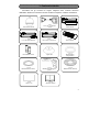
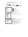
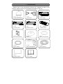
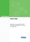
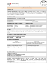
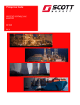
MANUALE UTENTE TVCD2523EXV - TVCD2523SHA Grazie per aver scelto un prodotto CIA Trading. z Per un corretto e sicuro utilizzo del dispositivo si prega di leggere attentamente il manuale utente. z Conservare questo manuale per eventuali riferimenti futuri z Le informazioni contenute all’interno del manuale potrebbero essere soggette a variazioni Norme di sicurezza 2 Prima di utilizzare questo dispositivo, si prega di leggere attentamente le istruzioni riportate e di rimuovere l’involucro di protezione prima di procedere con l’installazione. In caso di problemi, scollegare il cavo di alimentazione e rimuovere l’alimentatore prima di contattare il personale qualificato. Al fine di evitare scariche elettriche, non aprire e/o rimuovere i componenti del dispositivo. Richiedere l’intervento da parte di tecnici e/o personale qualificato. Utilizzare esclusivamente l’alimentatore fornito con il prodotto. Non utilizzare altri alimentatori in quanto potrebbero danneggiare il dispositivo o provocare incendi. Tenere opportunamente isolati cavi e spine in quanto il loro danneggiamento e/o usura potrebbe causare un corto circuito e danneggiare il dispositivo. NON collegare il dispositivo alla rete elettrica prima di aver completato l’installazione. Non ruotare manualmente l’obiettivo della telecamera. Non puntare la telecamera verso il sole o oggetti luminosi. Non posizionare la telecamera su oggetti elettrostatici. Non posizionare la telecamera su superfici soggette a vibrazioni o umidità Indice Norme di sicurezza Istruzioni 1. Contenuto Imballo 5 2. Installazione 6 3. Cablaggio 8 4. Telecomando 9 5. Programmazione iniziale 10 5.1 Accensione telecamera 10 5.2 Programmazione ID 10 5.3 Ripristino Impostazioni 10 5.4 Menu OSD 11 5.4.1 GROUP [Gruppo] 11 5.4.1.1 AUTOPAN [Scansione automatica] 11 5.4.1.2 GROUP1 ~ GROUP5 12 5.4.1.3 CRUISE 12 5.4.2 ALARM [Allarme] 13 5.4.3 MASK [Zone di mascheramento] 14 5.4.4 AUTO TRACKING [Puntamento automatico] 15 5.4.5 PROTOCOL [Protocollo] 15 5.4.6 ID [Identificazione Telecamere] 15 5.4.7 MISC [Altre funzioni] 16 3 Funzionamento 6. Modalità di controllo tramite telecomando 6.1 Selezione telecamera 17 6.2 Telecomando 17 6.3 Attivazione/Disattivazione Ingressi/Uscite Allarme 18 6.4 Richiamare – Salvare – Eliminare un Preset 18 6.5 Richiamo Preset successivo 18 6.6 Modalità Automatica (Auto Pan & Auto Cruise) 18 6.7 Funzione TRACKING [Puntamento automatico] 19 7. Controllo Remoto (RS485) 8. 7.1 Programmazione Iniziale 20 7.2 Connessione 20 7.3 Controlli 20 7.4 Protezione 20 Manutenzione e Pulizia 9. Risoluzione dei problemi 10. Specifiche Tecniche 11. Accessori 4 1-Contenuto Imballo Controllare che gli accessori di seguito raffigurati siano contenuti all’interno dell’imballo. Qualora la confezione dovesse risultare incompleta, contattare l’assistenza. 1.4.2 Cavi per il controllo remoto 1.4.3 Alimentatore 1.4.4 Cavo di alimentazione 1.4.5 Ricevitore a infrarossi 1.4.6 Telecomando 1.4.7 Pz.4 Batterie AAA 1.4.8 Coperchio 1.4.9 Distanziatore (trasparente) 1.4.10 Distanziatore (bianco) 1.4.11 Staffa per montaggio a parete 1.4.12 Distanziatore (bianco) TO AU 4 7 1.4.13 Chiave a U PAN/T ILT 1 8 5 2 9 6 3 0 AR K-50 3 1.4.1 Telecamera Dome 1.4.14 Manuale utente 5 2-Installazione Tenere cavi e spine debitamente isolati al fine di evitare di provocare un corto circuito e danneggiare il dispositivo. 2.4.1 Componenti A. Contenitore esterno B. Base C. Cupola D. Coperchio contenitore esterno E. Staffa per il montaggio a parete 2.4.2 Collegamento cavi per il controllo remoto 2.4.2.1 Inserire i Cavi per il controllo remoto (accessorio 1.4.2) all’interno dell’accessorio 1.4.11 Staffa per il montaggio a parete (come da figura a destra). 2.4.2.2 Installare la telecamera nella posizione prescelta. Prima dell’installazione, assicurarsi che la struttura dove si è scelto di installare la telecamera sia in grado di sostenerne il peso. (3.5Kg) 2.4.3 Posizionamento del Distanziatore impermeabile Posizionare il distanziatore impermeabile (accessorio 1.4.12) come illustrato nella figura a destra 2.4.4 Inserimento connettore Inserire il cavo di linea per il controllo remoto all’interno dell’apertura posta in cima alla telecamera, e collegare le due estremità del connettore. (6 pin e 7 pin, direzionale) 6 2.4.5 Fissaggio della telecamera alla staffa 2.4.5.1 Inserire la telecamera nel foro presente sulla staffa. 2.4.5.2 Posizionare il distanziatore impermeabile bianco (accessorio 1.4.10) e il distanziatore impermeabile trasparente (accessorio 1.4.9) come indicato in figura. 2.4.5.3 Posizionare il coperchio (accessorio 1.4.8) e chiudere con la vite. 2.4.5.4 Terminare l’assemblaggio della telecamera stringendo in senso orario la vite posta sopra il coperchio della telecamera con il cacciavite esagonale da 10mm. 2.4.6 Fissaggio della cupola Utilizzare la chiave a U (accessorio 1.4.13) e ruotare in senso orario. Non toccare l’obiettivo con le mani o con altri oggetti. Non ruotare l’obiettivo o rimuovere I componenti del dispositivo. Sigillare la giunzione tra la telecamera e la staffa con il silicone per evitare infiltrazioni d’acqua all’interno del dispositivo. 2.4.7 Installazione base 2.4.7.1 Fare riferimento alla figura 3.1 Cablaggio: collegare l’alimentazione, il cavo video e il cavo del ricevitore ad infrarossi, collegare, se necessario, il cavo Allarme e il cavo RS-485 per il controllo remoto. 2.4.7.2 Inserire le batterie nel telecomando e utilizzarlo per impostare l’ID della telecamera e il protocollo RS-485. Tenere cavi e spine debitamente isolati al fine di evitare di provocare un corto circuito e danneggiare il dispositivo. 7 3-Cablaggio 8 4-Telecomando Annulla / Visualizza ID telecamera Selezione telecamera 0 9 Tasti numerici ID telecamere / impostazione funzione Abilita/Disabilita Allarme/visualizzazione sottotitoli ARK-503 Programmazione Allarme/ visualizzazione sottotitoli 0 1 2 3 4 5 6 7 8 9 Zoom manuale WIDE (più focalizzata) / TELE (grandangolare) Messa a fuoco manuale (LONTANO / VICINO) Regolazione Diaframma (AISHUT) AUTO Controllo direzione telecamera / Funzione Cruise AUTO PAN/TILT Richiamo / Salvataggio / Eliminazione Preset Richiamo pozione Preset Su / Destra (Menu OSD) Giù / Sinistra (Menu OSD) Entra (voci Menu OSD) / Conferma Uscita (Menu OSD) / Salta 網路功能設定 (此機型無作用) z Attendere almeno 5 secondi prima di eseguire un nuovo comando. z Premere il tasto LK per annullare un comando. z I tasti senza descrizione non sono operative in questo modello. z Assicurarsi che non ci siano oggetti o persone tra il telecomando e il ricevitore a infrarossi. z La distanza massima tra il telecomando e il ricevitore deve essere di 7 metri. 9 5-Programmazione Attendere almeno 5 secondi prima di eseguire un nuovo comando, in caso di errore premere il tasto LK per annullare o per uscire dalla programmazione. 5.1 Accensione Alla prima accensione, la telecamera compirà una rotazione completa per il posizionamento automatico. 5.2 ID Telecamere E’ possibile impostare gli ID telecamere secondo due differenti procedure 5.2.1 Assegnazione diretta 5.2.1.1 Premere in sequenza i tasti 3→4→5→6→3→4→5→6→3→4→5→6→3 al termine della rotazione della telecamera, sarà possibile procedere con l’assegnazione dell’ID. 5.2.1.2 Se alla telecamera è collegato un monitor, sarà visualizzato il messaggio KEYIN NEW ID: - - - [INSERIRE NUOVO ID] 5.2.1.3 L’ID telecamera è composta da tre cifre comprese tra 001 e 255 inclusi. 5.2.1.4 Dopo aver digitato le tre cifre, l’ID sarà visualizzato sul monitor il messaggio di avvenuta memorizzazione e la telecamera selezionata ruoterà. (Se viene visualizzato il messaggio NEW ID: 000 [NUOVO ID: 000] significa che l’ID assegnato supera il numero massimo di 255 ID) 5.2.1.5 Controllo ID Telecamera 5.2.1.5.1 Premere il tasto LK per visualizzare l’ID telecamera sul monitor. 5.2.1.5.2 Premere il tasto CAM e digitare l’ID memorizzato e verificare che corrisponda alla telecamera da visualizzare. 5.2.1.6 Se è stato commesso un errore durante la programmazione, ripetere i passaggi da 5.2.1.1 a 5.2.1.4 5.2.2 Assegnazione dal menu OSD Consultare il paragrafo 5.4.6 ASSEGNAZIONE ID. Non ci sono limiti di tempo durante il processo di assegnazione ID telecamere. L’ID di default è 000. Se si utilizza una singola telecamera l’assegnazione ID non è necessaria. E’ accedere a tutte le funzione tramite il telecomando. L’ID 000 è visualizzato se è installata una sola telecamera. In caso di installazione di più telecamere la numerazione dovrà partire da 001. 5.3 Ripristino impostazioni Premere in sequenza i tasti 0→1→2→3→0→1→2→3→0→1→2→3→0 programmazioni verranno ripristinate. 10 . Tutte le 5.3.1 Ripristino impostazioni dal menu OSD Consultare il paragrafo 5.4.7.3 Ripristino impostazioni Tutte le impostazioni verranno ripristinate eccetto il PROTOCOLLO e l’ID telecamera. 5.4 MENU OSD Premere il tasto END per 5 secondi per visualizzare il menu OSD. Per uscire dal menu, premere e lasciare ripetutamente il tasto ESC fino alla scomparsa del messaggio 001 SYSTEM SETUP oppure premere il tasto LK per uscire rapidamente dalle funzioni del menu. Attendere la scomparsa del messaggio 001 SYSTEM SETUP prima di procedere. 001 SYSTEM SETUP → GROUP ALARM MASK TRACKING PROTOCOL ID MISC Su / Destra Giù / Sinistra DYNA9600 MENU OSD / Conferma Uscita(MENU OSD)/ Uscita Le funzioni MASK [MASCHERA] e TRACKING [PUNTAMENTO] sono facoltative. 001 SYSTEM SETUP GROUP-SET → AUTOPAN GROUP1 GROUP2 GROUP3 GROUP4 GROUP5 CRUISE 5.4.1 GROUP [GRUPPO] Selezionare la voce GROUP [GRUPPO] per la programmazione 5.4.1.1 AUTO PAN [SCANSIONE AUTOMATICA] 001 SYSTEM SETUP GROUP-SET AUTOPAN START-POINT → ENT. END-POINT ENT. X2 SPEED ENT. RUNNING Questa funzione permette di compiere una panoramica orizzontale delimitata da due posizioni di finecorsa definite dall’utente. - Selezionare la voce AUTO PAN START-POINT [punto di partenza]: selezionare la posizione della telecamera da cui deve partire la panoramica. END-POINT [fine panoramica]: selezionare la posizione finale della telecamera VELOCITA’ AUTO PAN: 2.5°~ 60°/sec SPEED [Velocità] : MIN = 2.5°/sec ; X1 = 5°/sec ; X2 = 10°/sec; X3 = 20°/sec ; X4 = 40°/sec; MAX = 60°/sec RUNNING: Visualizza in modo continuo la panoramica memorizzata. 11 5.4.1.2 GROUP 1~5 [GRUPPI da 1a 5] 001 SYSTEM SETUP GROUP-SET → DELAY SPEED RUNNING GROUP1 005 MAX ENT. Entrare nel menu di programmazione dei Gruppi Scegliere un gruppo da 1 a 5 DELAY corrisponde al tempo di permanenza di ciascuna inquadratura prefissata (PRESET) e può variare da 005 a 225 secondi. SPEED permette di impostare la velocità da utilizzare durante la registrazione di un CRUISE (vedi paragrafo successivo). I valori programmabili sono: da 2.5°/sec a 320°/sec SPEED [Velocità] : MIN = 2.5°/sec; X1 = 5°/sec; X2 = 10°/sec; X3 = 20°/sec; X4 = 40°/sec; X5 = 60°/sec; X6 = 80°/sec; X7 = 160°/sec; MAX = 320°/sec RUNNING: Visualizza la velocità memorizzata 5.4.1.3 CRUISE 001 SYSTEM SETUP GROUP-SET CRUISE START-RECORD → ENT. RUNNING ENT. Questa funzione consiste in una frequenza prefissata di spostamenti che la telecamera eseguirà automaticamente. Selezionare la voce CRUISE ( Registrazione Cruise) 1. Selezionare START-RECORD [Inizio Registrazione] 2. Premere il tasto END 3. Regolare la telecamera (incluso la direzione e lo zoom) prima di avviare la registrazione. Attenzione: Durante la registrazione non è abilitata la regolazione dello zoom. 5.4.1.3.1 RECORDING [REGISTRAZIONE] 001 SYSTEM SETUP CRUISE RECORDING 1. Premere il tasto END per avviare la registrazione 2. Utilizzare i tasti per il controllo diretto della telecamera. 3. Al termine della registrazione, premere il tasto END per salvare Durante la registrazione, sono operativi solo i tasti per il controllo direzionale della telecamera e i tasti END ESC LK D: 127 T: 655 : Indicano rispettivamente la data e il tempo della registrazione D: 127 T: 655 5.4.1.3.2 RUNNING CRUISE [VISUALIZZAZIONE CRUISE] 001 SYSTEM SETUP GROUP-SET CRUISE START-RECORD ENT. RUNNING → ENT. 12 Selezionare la voce RUNNING [Visualizzazione] 1. Premere il tasto END due volte per avviare il CRUISE 2. Premere qualsiasi tasto per terminare. Quando si esce dal MENU OSD premere AUTO → 6 per avviare un CRUISE. 5.4.2 ALARM [ALLARME] 001 SYSTEM SETUP Selezionare la voce ALARM ALARM → ALARM1 ALARM2 MODE DELAY OUTPUT ALARM1~2 seleziona l’ingresso allarme (fino a 2 ingressi) NO ingresso allarme normalmente aperto NC ingresso allarme normalmente chiuso OFF ingresso allarme disattivato NO NO OFF 005 OFF MODE [modalità allarme]: SAT Quando un evento allarme viene rilevato, la telecamera si posizionerà automaticamente in posizione1. Si attiva la funzione di puntamento automatico [tracking] e l’uscita allarme (ON) fino al termine del tempo di ritardo [DELAY] programmato dall’utente. ON La funzione allarme è abilitata. Quando un evento allarme viene rilevato, la telecamera si posizionerà automaticamente in posizione1 e si attiva l’uscita allarme (ON) fino al termine del tempo di ritardo [DELAY] programmato dall’utente. OFF Disabilita l’uscita allarme. DELAY Imposta il tempo di ritardo. Terminato il conto alla rovescia, la telecamera tornerà nella posizione in cui era prima dell’evento allarme. BY SAT Il tempo di ritardo richiamerà automaticamente il valore impostato al paragrafo 5.4.4 TRACKING [Puntamento] (Questa funzione è disponibile solo se la voce MODE è impostata su “SAT”) 005 Valore programmabile del tempo di ritardo da 005 ~ 255 sec. (Questa funzione è disponibile solo se la voce MODE è impostata su “ON” o ”OFF”) OUTPUT Abilita [ON] / Disabilita [OFF] l’uscita allarme (E’ possibile visualizzare la voce OUTPUT nel menu OSD, solo se la voce MODE è imposta su OFF) Premere il tasto LK per disattivare l’uscita allarme durante il conto alla rovescia del tempo di ritardo. Le funzioni di puntamento automatico non saranno interrotte. Premere il tasto LK per visualizzare lo stato dell’allarme. ” AL001” lampeggiante: Evento allarme in corso. ” AL001” fisso: Evento allarme rilevato e terminato. : Nessun evento allarme rilevato. 13 5.4.3 MASK [ZONE DI MASCHERAMENTO] E’ possibile impostare fino a 4 zone di mascheramento in una singola inquadratura del monitor. 001 SYSTEM SETUP GROUP ALARM MASK → NO .1 TRACKING PROTOCOL DYNA9600 ID E’ possibile programmare complessivamente fino a 24 zone di mascheramento. Selezionare la voce MASK e scegliere il numero della zona da programmare Premere il tasto END per entrare nel menu. 5.4.3.1 Programmazione MASK 001 SYSTEM SETUP MASK NO .1 RELOAD → ENT. CLEAR ENT. SAVE ENT. RELOAD [caricamento] Per richiamare una singola zona o una zona precedente CLEAR [elimina] Elimina una zona memorizzata. SAVE Per la programmazione e il salvataggio della posizione e della dimensione della zona di mascheramento. 5.4.3.2 POSIZIONE E DIMENSIONE MASK 001 SYSTEM SETUP MASK NO .1 MODIFY H-POS. → 08 V-POS. 08 08 H-SIZE 08 V-SIZE Selezionare la voce SAVE nella schermata precedente. Utilizzare i tasti UP [su] e DN [giù] per la regolazione della posizione e della dimensione della zona. Uscire dal sottomenu SAVE per terminare la programmazione. H-POS. Regolazione posizione orizzontale V-POS. Regolazione posizione verticale 14 H-SIZE Regolazione larghezza V-SIZE Regolazione altezza 5.4.4 AUTO TRACKING [PUNTAMENTO AUTOMATICO] DELAY Impostazione del tempo di ritardo da 005 a 255 secondi. 001 SYSTEM SETUP TRACKING DELAY MODE RUNNING → 005 SAT2 ENT. MODE [modalità puntamento automatico] SAT1 Nel caso in cui l’oggetto puntato non è in movimento o è al di fuori dell’inquadratura, il tempo di ritardo si attiva. Al termine del conto alla rovescia, la telecamera passerà dalla modalità di puntamento alla modalità di standby. SAT2 Il tempo di ritardo si attiva quando viene abilitata la funzione di puntamento automatico. Al termine del conto alla rovescia, la telecamera passerà dalla modalità di puntamento alla modalità di standby RUNNING Attiva la funzione di puntamento automatico. (Un asterisco Ä comincerà a lampeggiare nell’angolo in alto a sinistra del monitor.) Il puntamento automatico potrebbe non funzionare correttamente in caso di inquadrature in assenza di luce o, viceversa, in presenza di troppa luce. 5.4.5 PROTOCOL [PROTOCOLLO] 001 SYSTEM SETUP GROUP ALARM MASK TRACKING PROTOCOL → DANA9600 ID Selezionare la voce PROTOCOL comunicazione seriale RS-485) (per sistemi con Selezionare il tipo di protocollo da utilizzare per il controllo remoto della telecamera (DVR o tastiera di controllo): DYNACOLOR9600 ELITAR2400 CHIPER9600 PELCOD2400 PELCOP4800 PELCOP9600 Il Protocollo non può essere impostato tramite controllo remoto (RS-485) ma SOLO tramite telecomando. 5.4.6 ID 001 SYSTEM SETUP ID OLD- ID: 0 0 0 NEW- ID:- - ↑ KEYIN NUM<000-255> Selezionare la voce ID e confermare con il tasto END Assegnare il nuovo ID alla telecamera (tre cifre comprese tra 001~255 inclusi). Premere il tasto END per memorizzare. L’ID Telecamera non può essere impostato tramite controllo remoto (RS-485). E’ possibile assegnare l’ID tramite il telecomando 15 5.4.7 MISC [ALTRO] (SPEED [Velocità], Auto-flip, DEFAULT [Ripristino Impostazioni]) 5.4.7.1 SPEED [Velocità] 001 SYSTEM SETUP MISC → SPEED AUTO-FLIP DEFAULT MAX ON ENT. Selezionare la voce SPEED [Velocità] Impostare la velocità da 2.5°/sec a 160°/sec MIN = 2.5°/sec; X1 = 5°/sec; X2 = 10°/sec; X3 = 20°/sec; X4 = 40°/sec; X5 = 60°/sec; X6 = 80°/sec; MAX = 160°/sec La velocità di rotazione della telecamera può variare se controllata dal joystick. 5.4.7.2 AUTO-FLIP 001 SYSTEM SETUP MISC SPEED → AUTO-FLIP DEFAULT MAX ON ENT. Questa funzione permette di seguire il target oltre la verticale (90°). La telecamera ruoterà automaticamente di 180° per consentire una visione migliore. Selezionare la voce AUTO-FLIP ON = funzione abilitata OFF = funzione disabilitata 5.4.7.3 DEFAULT 001 SYSTEM SETUP MISC SPEED AUTO-FLIP → DEFAULT 16 MAX ON ENT. Questa funzione permette di resettare tutte le impostazioni finora memorizzate eccetto il Protocollo e l’ID delle telecamere e ripristinando le impostazioni di fabbrica. 6-Modalità di controllo tramite telecomando 6.1 Selezione ID Telecamera 6.1.1 Premere il tasto CAM. Il messaggio CALL ID<001-255>: - - - verrà visualizzato. 6.1.2 Inserire l’ID Telecamera. Esempio: Per selezionare l’ID della telecamera 1 premere in sequenza I tasti CAM →0→0→1. L’operazione dovrà essere eseguita entro 5 secondi. Selezionando un ID corretto, la telecamera verrà visualizzata sul monitor. In caso contrario, nessuna immagine verrà visualizzata. Se non si conosce l’ID della telecamera da selezionare, premere il tasto LK per cercare l’ID. 6.2 Telecomando Dopo avere selezionato la telecamera desiderata tramite ID, premere i tasti direzionali o il tasto per il controllo dell’obiettivo per controllare la telecamera. Tenere premuto per il controllo e rilasciare per terminare l’operazione. Durante l’operazione di controllo telecamera, un simbolo relativo allo stato apparirà in basso sullo schermo: Direzione della telecamera: in alto , in basso , a sinistra , a destra in alto a sinistra , Tilt (inclinazione) in alto a destra sinistra , Tilt (inclinazione) in basso a destra Controllo Zoom: ZOOM , Tilt (inclinazione) , Tilt (inclinazione) in basso a , z/Z Controllo Messa a fuoco: FOCUS Regolazione Diaframma: IRIS f/F MIN ~ MAX La velocità di rotazione può variare in base alla regolazione dello zoom (5~60°/sec). Per la programmazione della velocità, consultare la voce del menu SPEED[VELOCITA’] Quando i simboli sul monitor cominciano a lampeggiare, la telecamera è arrivata al termine della corsa. 17 6.3 Attivazione/Disattivazione Ingressi/Uscite Allarme 6.3.1 Premere il tasto EX. Sullo schermo apparirà il messaggio SET EX<1 - 5> 6.3.Premere i tasti da 1 a 2 per l’attivazione/disattivazione [ON/OFF] degli ingressi/uscite allarme da 1 a 2. Esempio: Ingresso allarme 1: EX→1→ON oppure EX→1→OFF 6.3.3 Premere 5 per attivare/disattivare [ON/OFF] l’uscita allarme Esempio: Uscita allarme 5: EX→5→ON oppure EX→5→OFF Quando l’ingresso allarme 1 rileva un evento allarme, la telecamera corrispondente muoverà automaticamente secondo la posizione prefissata 1. Per la programmazione della modalità di allarme, consultare la voce del menu ALARM[ALLARME] 6.4 PRESET 6.4.1 Call – Richiamo PRESET Premere il tasto PRE una volta, alla schermata CALL PRESET: - - inserire l’ID della telecamera. Esempio: PRE→0→2 per richiamare il preset02 6.4.2 Save – Salvataggio PRESET Premere il tasto PRE due volte, alla schermata CALL PRESET: - - inserire l’ID della telecamera. Esempio: PRE→PRE→1→0 per salvare il preset10 6.4.3 Clear – Cancella PRESET Premere il tasto PRE tre volte, alla schermata CALL PRESET: - - inserire l’ID della telecamera. Esempio: PRE→PRE→PRE→0→6 per cancellare il preset06 E’ possibile programmare fino a 62 preset (da 01 a 62). 6.5 Richiamo PRESET successivo Premere e rilasciare il tasto FUN per richiamare il preset01. Sarà visualizzato sullo schermo il messaggio CALL PRESET : 01 OK. Ripetere per la visualizzazione consecutiva dei preset memorizzati. Dopo aver premuto il tasto FUN, le funzioni autopan e autocruise si interromperanno. 6.6 Modalità Automatica (include Auto Pan, Group, Cruise e Auto Tracking) Premere il tasto AUTO. Sullo schermo verrà visualizzato il messaggio CALL GROUP <0 - 7> : AUTO→0 = Funzione Auto Pan (paragrafo 5.4.1.1 AUTOPAN per la programmazione.) AUTO→1 = Per visualizzare in automatico i Cruise da 001 a 032 AUTO→2 = Per visualizzare in automatico i Cruise da 033 a 064 AUTO→3 = Per visualizzare in automatico i Cruise da 065 a 096 AUTO→4 = Per visualizzare in automatico i Cruise da 096 a 128 AUTO→5 = Per visualizzare in automatico in automatico i Cruise da 001 a 128 AUTO→6 = Per visualizzare in automatico il Cruise Registrato 18 AUTO→7 = Modalità di Puntamento Automatico Per eseguire l’autocruise di un gruppo, verificare che almeno 2 preset siano presenti in ciascun gruppo. Premere un qualsiasi tasto direzionale per terminare la modalità automatica. Al termine, sono necessari circa 20 secondi prima che la telecamera ritorni allo stato precedente. 6.7 Funzione di Puntamento Automatico Regolare la telecamera (Direzione e zoom) prima di avviare la funzione di puntamento automatico. Premere i tasti AUTO→7 per attivare la funzione (Consultare il paragrafo 5.4.4 TRACKING [Puntamento automatico] ) 7-Controllo remoto (RS-485) 7.1 Programmazione iniziale Per il controllo in remoto tramite DVR o tastiera di controllo, è necessario programmare il protocollo di comunicazione del DVR o della tastiera di controllo. Consultare il paragrafo 5.4.5 PROTOCOL. [PROTOCOLLO] 7.2 Connessione Consultare il paragrafo 3 Cablaggio . Questo dispositivo è abilitato al collegamento con 128 unità ed è compatibile per applicazione con altri sistemi di video-sorveglianza. 7.3 Controlli Consultare il manuale utente del dispositivo di controllo installato per l’attivazione e il funzionamento della telecamera. 7.4 Protezione Al fine di evitare di perdere dati fondamentali al riconoscimento della telecamera installata durante il collegamento di un DVR o di una tastiera di controllo, l’ID e il protocollo sono programmabili solo tramite il telecomando. 19 8-Manutenzione Pulizia Utilizzare un panno asciutto e non abrasivo per la pulizia della telecamera. Polvere e graffi potrebbero compromettere la visibilità del dispositivo. Pulizia dell’obiettivo Utilizzare esclusivamente un prodotto specifico per la rimozione della polvere dall’obiettivo. Rimozione di macchie difficili Per la rimozione di macchie difficili dalla superficie della telecamera, utilizzare un panno morbido inumidito con detergente delicato diluito, asciugare con un panno asciutto e non abrasivo. Durante la pulizia, fare attenzione a non graffiare la superficie della telecamera o a lasciare macchie di bagnato che potrebbero compromettere la qualità dell’immagine Non utilizzare benzene, diluenti o benzina e altri solventi corrosivi 20 9-Risoluzione dei problemi 9.1 Non c’è immagine sullo schermo dopo aver montato correttamente la telecamera. 9.1.1 Assicurarsi che il connettore di uscita video della telecamera sia collegamento correttamente all’ingresso del monitor. 9.1.2 Controllare il collegamento dei cavi e dell’alimentazione. 9.2 Non è possibile effettuare la ricerca di un preset esistente. 9.2.1 Assicurarsi che il preset sia in modalità funzionamento normale. 9.2.2 Assicurarsi che in uno specifico gruppo siano presenti due o più preset. 9.2.3 Verificare di aver impostato tutti i preset di un unico gruppo nello stesso modo. 9.3 Non è possibile eseguire il controllo della telecamera 9.3.1 Controllare che tutti i cavi siano correttamente collegati. 9.3.2 Verificare di aver digitato correttamente l’ID telecamera o di aver selezionato la telecamera esatta prima di aver avviato il controllo. 9.3.3 Verificare che il telecomando punti in direzione del ricevitore. Verificare che la distanza non superi i 7 metri. Verificare il livello delle batterie del telecomando. 9.3.4 Verificare che il protocollo di comunicazione impostato sia corretto (solo per il controllo remoto tramite RS485) 9.4 Presenza di disturbo durante il controllo della telecamera 9.4.1 Verificare che il cavo non faccia falso contatto e che l’interferenza non dipenda dal movimento del cavo. 9.4.2 Assicurarsi di aver utilizzato un cavo in PVC (doppino) adatto alla comunicazione tramite RS485. 9.4.3 Assicurarsi che la distanza per il controllo remoto rientri nei parametri. Per un supporto tecnico, contattare l’assistenza di zona. 21 10-Specifiche tecniche TELECAMERA Sensore: TVCD2523EXV: SONY EXVIEW 1/4" CCD a colori (Giorno/Notte) TVCD2523SHA: SONY SUPER HAD 1/4" CCD a colori (Giorno/Notte) TVCD2523EXVT: SONY EXVIEW 1/4" CCD a colori (Giorno/Notte) Sincronizzazione: Interna Risoluzione: 480 linee TV Sensibilità: da 0.1 Lux a 0.002 Lux Obiettivo: Canon Zoom ottico 23x (Zoom digitale10x) f =3.6 ~ 82.8mm / F =1.6 ~ 3.8mm Rapporto segnale/rumore: 50dB (AGC off) Messa a fuoco: Automatica / Manuale Shutter elettronico: PAL:1/50 ~ 1/100,000 Sec. Uscita Video: 1Vp-p / 75ohm - composito Correzione α: 0.45 / 1 Controllo Guadagno: Super AGC 0 ~ 36dB (automatico) Bilanciamento Bianco: ATW 2500°~9500°K Automatico / Manuale Controluce: Super BLC / 48 zone impostabili Caratteristiche di Funzionamento Rotazione: Auto Pan / Preset programmabili / Flip over Angolo di rotazione: Orizzontale (Pan) 0°~375° / Verticale (Tilt) 0°~95° Velocità: Auto:2.5~60˚/Sec - Manuale:2.5~160˚/Sec - Preset: Max.320˚/ Sec Collegamenti: 256 max. Controllo: Internet; Telecomando; Seriale RS485 Alimentatore Ingresso DC 13.5V /2.2A Caratteristiche di funzionamento: Dimensioni / Peso: TVCD2523EXV/ TVCD2523SHA: Temperat. -30°C ~ 60°C / Umidità: 30% ~ 90% TVCD2523EXV / TVCD2523SHA : Ø 210 x H269mm / 3.5Kg Certificazioni: CE, FCC, IP66 Tutte le caratteristiche possono variare in base al modello 22 USER’S MANUAL TVCD2523EXV - TVCD2523SHA TVCD2523EXVT 23 Thanks for your purchase of our product. z In order to make good use of this product, please read this user’s manual carefully. z In order to use this product correctly and safely; be familiar with all operation steps. z Please keep this user’s manual for future reference. z This document contains proprietary information, which is protected by copyright. z All rights are reserved. No part of this document may be photocopied reproduced or translated to another language without the prior written consent of YUDOR, Inc. z The information contained in this document is subject to changes without notice. 24 SAFETY WARNING Before using this product, please read installation instructions carefully and remove the protective lining from the dome before proceeding with set up. In case of failure, disconnect power or remove power supply before contact our service personnel. To avoid electric shocks, do not disassemble this product on your own. Be sure to ask a skilled technician for the job. Use enclosed power supply only. Do not use other type of power supply, or the product may be damaged or fire can be triggered. Keep unconnected wires, plugs, duly insulated, or they might cause short circuit and damage this product. Do NOT connect power to the unit until all installation steps are completed. Do not turn the camera lens with your hand, doing so might damage camera. Do not point this camera to the sun or a shining object, do not put it on a static object; doing so might damage the camera. To avoid damage, do not load this camera in a place subject to vibration, humidity or a dusty environment. 25 Table of Contents Safety warning 25 Instructions 1. Accessories 28 2. Installation 29 3. Cable Connection 32 4. Infrared Remote Control 33 5. Initial Programming 5.2 Camera ID setup 34 5.3 Load Default 35 5.4 OSD MENU FUNCTION SETUP 35 5.4.1 GROUP (Auto Pan, Group Auto Cruise, Recorded Cruise) 26 35 5.4.1.1 AUTOPAN 36 5.4.1.2 GROUP1 ~ GROUP5 36 5.4.1.3 CRUISE 36 5.4.2 ALARM (Alarm Mode Setup) 37 5.4.3 MASK 38 5.4.4 TRACKING 39 5.4.5 PROTOCOL 40 5.4.6 ID 40 5.4.7 MISC (Manual control speed setup, Auto Flip, Default) 40 Operation 6. Infrared remote control mode 6.1 Select Camera - By Input camera ID 42 6.2 Remote control 42 6.3 Alarm and Output On / Off 42 6.4 Preset Positions CALL, SAVE and CLEAR 43 6.5 Recall Preset Positions 43 6.6 Auto Pan Mode and Group Auto Cruise Mode 43 6.7 Speed activate Auto Tracking Function 43 7. RS-485 Control mode 7.3 Controls 44 7.4 Protecting 44 Remarks 8. Maintenance & cleaning 44 9. Troubleshooting 45 10. Specifications 46 27 1-Accessories Please check if the accessories enclosed are completed. If there is any shortage, please contact your local dealer and replace a new one. 1.4.1 Outdoor Speed Dome 1.4.2 Control line 1.4.3 1.4.4 1.4.5 Infrared receiver 1.4.6 Infrared remote control 1.4.7 No. 4 AAA Batteries 1.4.8 Stable Lid 1.4.9 Spacer (Transparent) 1.4.10 Spacer (White) 1.4.11 Wall-mount Bracket 1.4.12 Spacer (White) 1.4.13 U Shape Spanner 1.4.14 User’s manual 28 TO AU 4 7 AC Power Line PAN/T ILT 1 8 5 2 9 6 3 0 AR K-50 3 Power supply 2-Installation 2.1 Names of parts A. Outer layer of base B. Base C. Cover D. Stable Lid E. Wall mounted Bracket 2.2 Insert control line 2.2.1 Insert accessories 1.4.2 Control Line into accessories 1.4.11 Wall Mount Bracket (As Diagram on right). 2.2.2 Install speed dome in an appropriate position. Before installation, make sure the structure of location you choose can hold the weight of camera. (3.5Kg) 2.3 Lay on Waterproof Spacer Lay on accessories 1.4.12 Waterproof spacer, (As Diagram on right). 2.4 Plug in connector Insert control line into gap on the side of top of speed dome, and plug in 2 sets of connector. (6 pin and 7 pin, directional) 29 2.5 Assembling speed Dome with Bracket 2.5.1 Insert speed dome into round hole of bracket. 2.5.2 Lay on accessories 1.4.10 Waterproof spacer (White)、1.4.9 Waterproof spacer (Transparent) as Diagram. 2.5.3 Lay on accessories 1.4.8 Stable Lid, screw with hand. 2.6 Stable speed dome Stable speed dome with 10mm hexagonal Spanner, Turn clockwise. 2.7 Put on Dome Cover Use Accessories 1.4.13 U shape spanner, Turn clockwise. Do not touch lens with your hands or other objects. Do not turn the lens or remove other parts. Doing so may cause damage. Make sure junction between dome cover、speed dome and bracket are air tight sealed with Silicon glue to keep speed dome waterproof. 30 2.8 Basic Setup 2.8.1 Please connect power line, video, Infrared receiver first, Connect RS-485 control, alarm in and out if necessary. (Please refer to 3.4 Connection Chart and 3.5 Cable specification). 2.8.2 Load batteries into remote controller, point to infrared receiver, setup camera ID and Protocol of RS-485. Please refer to 4 Infrared Remote control and 5 Initial Programming . Keep unconnected wires, plugs, duly insulated, or they may cause short circuit and damage this product. 31 3-Cable Connection 32 Cable specification: Power line: 18AWG-2C Video cable: 5C2V(5CFB) 168 Alarm cable: 22AWG-4C Infrared receiver insulation cable: 22AWG-3C RS-485 PVC instrument cable (pair type): 22AWG-1P To insure reliable operation, above requirements must be fulfilled . To obtain better quality, higher standard cable for long-distance transmission is recommend. 33 4-Infrared Remote control Clear / Camera ID Display key Camera selected key. 0 9 Number key for Input camera ID /Function setting Alarm/subtitle display on or off ARK-503 Alarm/subtitle display setting 0 1 2 3 4 5 6 7 8 9 Manual zooming (WIDE / TELE) Manual focusing (FAR / NEAR) Iris adjustment (AISHUT) AUTO AUTO PAN/TILT Camera direction control key and auto cruise key Call / Save / Clear preset positions Recall preset position Up / Right (OSD Menu) Down/Left (OSD Menu) Enter into (OSD Menu) / OK Exit from (OSD Menu) / Skip 網路功能設定 (此機型無作用) z Make sure to press a key after another within 5 seconds, or you will make an invalid input. z In case of erroneous input, press LK to clear. z Keys without a description are not operational in this model. z Make sure that there is nothing between the infrared receiver and the remote control. z Effective distance of the remote control is 7 meters. z If you find that the effective distance of the remote control is shortened, replace the batteries with new ones of the same spec. 34 5-Initial Programming Be sure to keep the remote control within 7 meters from the receiver. All inputs shall be made within 5 seconds, or the input mode would be cancelled automatically. In case of erroneous input, press LK to clear or escape from the operating mode. 5.1 Power on After connect power for the first time, the camera will rotate once for reposition, which is normal. 5.2 Camera ID setup. There are two ways to setup camera ID 5.2.1 Direct setup camera ID 5.2.1.1 Input digit 3→4→5→6→3→4→5→6→3→4→5→6→3 then camera will rotate once, indicate that camera is waiting for input camera ID 5.2.1.2 If a monitor is connecting to camera then the screen will show KEYIN NEW ID: - - - , each digit input will show on the screen and the meantime camera will 〝nod〞. After that, you can input next digit. 5.2.1.3 Camera ID is three digits totally. It can be set from 001~255. 5.2.1.4 After input all three digits, new ID will show on the screen and camera will rotate once and go through Default preset point group 1 that indicate you already finished camera ID set up. (If NEW ID: 000 show on the screen means your ID input exceed 255) 5.2.1.5 Check camera ID 5.2.1.5.1 Press LK button on the remote control, camera ID will show on the screen. 5.2.1.5.2 Press CAM button on the remote control then input camera ID (Three digits) check is the new camera ID show on the screen? 5.2.1.6 If any mistake made on the process of camera ID setup please repeat from 5.2.1.1 to 5.2.1.4 5.2.2 Camera ID setup from OSD MANUAL Please refer 5.4.6 ID-SET. 35 There is no time limit on the process of camera ID setup Default of camera ID is〝000. If you only use one camera you don’t have to setup camera ID. You can operate all function through remote control directly. Camera ID〝000〞is only for single camera user, if you have more than one camera you have to setup camera ID from〝001〞. 5.3 Load Default Input digit 0→1→2→3→0→1→2→3→0→1→2→3→0 , then all setup will be cleared and back to default. 5.3.1 Use OSD (Please refer to 5.4.7.3 DEFAULT) to load Default All Setup will restore DEFAULT except PROTOCOL and camera ID. 5.4 OSD MENU FUNCTION SETUP By holding END (for 5 seconds), OSD menu will show on the screen that indicates camera is standing by for system setup. To escape from the menu, you may press and release ESC repeatedly until 001 SYSTEM SETUP disappears or you may press LK to escape rapidly from the function menu. To do so, you must wait until 001 SYSTEM SETUP disappears before proceeding. 001 SYSTEM SETUP → GROUP ALARM MASK TRACKING PROTOCOL ID MISC Up / Right key Down / Left key DANA9600 Enter (OSD MANU) / OK key Escape (OSD MANU)/ Escape key 5.4.1 GROUP 001 SYSTEM SETUP GROUP-SET → AUTOPAN GROUP1 GROUP2 GROUP3 GROUP4 GROUP5 CRUISE 36 Select→GROUP 5.4.1.1 AUTO PAN 001 SYSTEM SETUP GROUP-SET AUTOPAN START-POINT → ENT. END-POINT ENT. X2 SPEED ENT. RUNNING Select →AUTO PAN START-POINT: PAN LIMIT TO THE LEFT END-POINT : PAN LIMIT TO THE RIGHT AUTO PAN SPEED SETUP 2.5 ゚~ 60 ゚/s MIN, X1, X2, X3, X4, MAX 2.5 ゚ 5 ゚ 10 ゚ 20 ゚ 40 ゚ 60 ゚ RUNNING: Running Auto pan 5.4.1.2 GROUP1~ 5 Dwell time and cruise speed of group auto cruise set 001 SYSTEM SETUP GROUP-SET → DELAY SPEED RUNNING GROUP1 005 MAX ENT. up Enter into group setup Choose group from group1~5 DELAY-SET is to setup dwell time of each preset position 005 ~ 255 seconds 005 ~ 255 stand for 005 ~ 255 seconds SPEED-SET is to set the cruise speed of group auto cruise from 2.5 ゚/sec ~ 320 ゚/sec MIN, X1, X2, X3, X4, X5, X6, X7, MAX 2.5 ゚ 5 ゚ 10 ゚ 20 ゚ 40 ゚ 60 ゚ 80 ゚ 160 ゚ 320 ゚ RUNNING: Running group auto cruise 5.4.1.3 CRUISE 001 SYSTEM SETUP GROUP-SET CRUISE START-RECORD → ENT. ENT. RUNNING Select →CRUISE ( Recorded Cruise) 1. Select START-RECORD 2. Press END and prepare to record 3. Adjust camera (including direction and zoom) to the spot you want to start recording. When recording, zoom cannot be adjusted. 37 5.4.1.3.1 RECORDING 001 SYSTEM SETUP CRUISE RECORDING 1. Press END to start recording 2. Use direction key to control camera to the spot need to be monitoring 3. When finish recording, press END to save D: 127 T: 655 When recording only camera direction control key and END、ESC、LK key can function。 〝D: 127〞 , 〝T: 655〞Show on monitor indicate data and time left to be recorded 5.4.1.3.2 RUNNING CRUISE (PRECORDED CRUISE) 001 SYSTEM SETUP GROUP-SET CRUISE START-RECORD ENT. RUNNING → ENT. Select→ RUNNING 1. Press END twice to start cruise 2. Press any key to stop When exit OSD MENU,press AUTO → 6 to start cruise. 5.4.2 ALARM 001 SYSTEM SETUP ALARM → ALARM1 ALARM2 MODE DELAY OUTPUT NO NO OFF 005 OFF Select→ALARM ALARM1~2 alarm trigger mode setup NO alarm triggered when short circuit NC alarm triggered when broken circuit OFF no alarm will be triggered MODE:set alarm mode: SAT When alarm 1 triggered camera will automatically goes to preset position 1,activate auto tracking function and output switch “ON” until finish delay time count down. ON When alarm 1 triggered camera will automatically goes to preset position 1,activate output switch “ON” until finish delay time count 38 down. OFF alarm output goes off DELAY:Delay time setup, after finish delay time count down , camera will back to original status before alarm triggered. BY SAT Delay time will automatically go with 5.4.4 TRACKING delay time setup。(Can be set only when ALARM MODE set on SAT) 005 Delay time can be set from 005 ~ 255 秒。(Can be set only when ALARM MODE set on “ON” or ”OFF”) OUTPUT:switch of small electric facility (Max load 300mA), ON OFF (Only when MODE is setup to OFF, OUTPUT will show on the OSD MENU) ※ Output switch goes off by press LK key during delay time count down. Auto tracking functions keep working. ※ Press LK key to know the current status of alarm. Twinkling ” AL001”: ALARM1 keeping triggered. ” AL001”: ALARM1was triggered, but already goes off. : No alarm been triggered. 5.4.3 MASK 001 SYSTEM SETUP GROUP ALARM MASK → NO .1 TRACKING PROTOCOL DANA9600 ID MISC Only M / T-Series provide Function Only 4 blocks of privacy masking can be set in a single frame of monitor. Maximum 24 blocks of privacy masking can be set。 Choose one block from No.1 ~ No. 24, Press END to enter. 5.4.3.1 RELOAD, CLEAR, SETUP BLOCK OF MASKING 001 SYSTEM SETUP MASK NO .1 RELOAD → ENT. ENT. CLEAR SAVE ENT. RELOAD Load masking or reload previous setup。 CLEAR Clear block of masking SAVE Setup position and size of masking 39 5.4.3.2 SETUP POSITION AND SIZE OF MASKING 001 SYSTEM SETUP MASK NO .1 MODIFY H-POS. → 08 V-POS. 08 08 H-SIZE 08 V-SIZE V-SIZE Enter SAVE, Use UP 、 DN key to adjust position and size of masking. Exit SAVE to finish setup. H-POS. Horizontal position adjustment V-POS. Vertical position adjustment H-SIZE Horizontal size adjustment Vertical size adjustment 5.4.4 TRACKING 001 SYSTEM SETUP TRACKING DELAY MODE RUNNING Only T-Series provide Auto Tracking Function → 005 SAT2 ENT. DELAY Delay time setup, can setup from 005 ~ 255Secs MODE Tracking mode setup SAT1 When the object been tracking make no move or out of range, start to count down delay time, when finish count down, camera automatically goes back to previous activate position to stand by. SAT2 When activate Auto tracking function, start to count down delay time, when finish count down, camera automatically goes back to previous activate position to stand by. RUNNING Activate Auto tracking function (Ä twinkles on upper-left corner of monitor after activate. Auto tracking function may be influenced by dark environments or lights. 40 001 SYSTEM SETUP GROUP ALARM MASK TRACKING PROTOCOL → DANA9600 ID MISC 5.4.5 PROTOCOL Select→PROTOCOL (For RS-485 systems) DYNA9600 (DYNACOLOR Rate 9600) ELITAR2400 (ELITAR Rate 2400) CHIPER9600 (CHIPER Rate 9600) LILIN9600 (LILIN Rate 9600) PELCOD2400 (PELCO-D Rate 2400) PELCOP4800 (PELCO-P Rate 4800) PELCOP9600 (PELCO-P Rate 9600) Please choose protocol that match to your control device (DVR or KEY PAD). Protocol can not be set through RS-485 The only way to set protocol is through Infrared remote control 5.4.6 ID 001 SYSTEM SETUP ID OLD- ID: 0 0 0 NEW- ID:- - - Select→ID Setup new camera ID (three digits 001~255) then press END to store. ↑ KEYIN NUM<000-255> Camera ID cannot be setup through RS-485. Only way to setup camera ID is through infrared remote control. 5.4.7 MISC (Manual control speed setup, Auto flip, Default) 41 5.4.7.1 SPEED 001 SYSTEM SETUP MISC → SPEED AUTO-FLIP DEFAULT MAX ON ENT. Select→SPEED SPEED Manual From 2.5 ゚/sec to control speed 160 ゚/sec MIN, X1, X2, X3, X4, X5, X6, MAX 2.5 ゚ 5 ゚ 10 ゚ 20 ゚ 40 ゚ 60 ゚ 80 ゚ 160 ゚ Rotation speed can be variable by controlling a joystick 5.4.7.2 AUTO-FLIP 001 SYSTEM SETUP MISC SPEED → AUTO-FLIP DEFAULT MAX ON ENT. AUTO-FLIP Select→AUTO-FLIP ON OFF 5.4.7.3 DEFAULT 001 SYSTEM SETUP MISC SPEED AUTO-FLIP → DEFAULT 42 MAX ON ENT. DEFAULT All Setup will restore DEFAULT Except PROTOCOL and camera ID. setup 6-Infrared Remote Control mode 6.1 Select Camera - By Input camera ID 6.1.1 Press CAM then CALL ID<001-255>: - - - show on the screen. 6.1.2 Input CAMERA ID (Three digits) then you can set function or control camera. Example: To select ID 1 camera: CAM →0→0→1, the operation must be completed within 5 seconds, or the Camera ID Selection mode would be cancelled automatically. When selecting a correct Camera ID, the Camera ID will appear on the screen; otherwise no display would appear on the screen. If you do not know the Camera ID, Press LK to check the Camera ID. 6.2 Remote control After you select the camera you want by input camera ID, then you may press the direction key or the lens control key to control it. Press it down for operation and release it to stop. When you operate, a status code will appear below the screen, such as: Direction key Up , Down , Left , right , Tilt left up , Tilt right up down , ZOOM z/Z, FOCUS IRIS adjust IRIS from MIN ~ MAX。 , Tilt left down , tilt right f/F The rotation speed will change according to the zoom lens in or out.(5~60 ゚ /sec). For speed setting, please refer to MENU SPEED-SET menu setting. When twinkles means this direction is already to the end. 6.3 Alarms and Output On/Off 6.3.1 Press EX screen shows SET EX<1 - 5> 6.3.2 Press 1~4 to choose alarm 1~4 on or off. Example: Alarm input 1: EX→1→ON / EX→1→OFF 6.3.3 Press 5 to choose output ON or OFF Example: Output ON: EX→5→ON / Output OFF: EX→5→OFF When alarm input 1 triggered, the camera will corresponding goes to preset position1For alarm mode setting, please refer to MENU ALARM-SET. Output switch can control small electric facility Max Load 300mA. 43 Functional only when alarm-set:MODE is OFF 6.4 Preset positions Call, Save and Clear 6.4.1 Call Press PRE once then input camera ID CALL PRESET: - PRE→0→2 call preset 02 6.4.2 Save Press PRE twice then input camera ID CALL PRESET: - PRE→PRE→1→0 save preset 010 6.4.3 Clear Press PRE three times then input camera ID PRE→PRE→PRE→0→6 CALL PRESET: - - clear preset 06 Preset position input limit from 01 to 62. 6.5 Call Next Preset Position By press and release FUN key you may recall preset position 01 and see CALL PRESET : 01 OK on the screen. And by repeating this method you may check all preset positions. When execute FUN, the auto pan and group auto cruise will stop. 6.6 Execute Auto Pan Mode, Group Auto Cruise Mode, (Recorded) Cruise Mode and Auto Tracking Mode Press AUTO screen shows CALL GROUP <0 - 7> : AUTO→0:Auto Pan (Refer5.4.1.1 Auto Pan SET to set auto pan limit.) AUTO→1: cruise preset 01 ~ 16 AUTO→2: cruise preset 17 ~ 32 AUTO→3: cruise preset 33 ~ 48 AUTO→4: cruise preset 49 ~ 62 AUTO→5: cruise preset 01 ~ 62 AUTO→6: Recorded cruise AUTO→7: Auto Tracking Mode To execute group auto cruise, at least 2 positions shall be preset in each group. Press any direction key to stop AUTO mode. When camera regains power after lost it, need 20 sec to restart and back to previous status. 44 6.7 Speed activate Auto Tracking Function Adjust camera (Direction and zoom) to the spot to start auto tracking, Press AUTO→7 to activate Auto Tracking. (Setup please refer to 5.4.4 TRACKING) 7-RS-485 Control mode 7.1 Initial Programming If camera needs to connect to DVR or control panel (KEY PAD) you need to setup protocol match to DVR’s or control panel‘s protocol. Please refer to 5.4.5 PROTOCOL. This device is working in standard RS-485 communication format at the bps as set. 7.2 Connection Please refer to 3 Wire Connections and the wire specification. The reference connection diagram shows simple layout and this device is able to connect with as many as 128 units and integrated application with other systems. 7.3 Controls All function depends on the control device such as DVR or Key Pad you choose. Function can be performed only if control device can support. 7.4 Protecting To avoid lose control of camera when connecting to DVR or KEY PAD; (They might mistakenly reset camera ID or protocol). Camera’s protocol and ID Can only be set through infrared remote control. 45 8-Maintenance & cleaning Daily cleaning Use a piece of soft and dry cloth to wipe off the dust from the dome cover. Dirt or scratch may influence focusing. Lens cleaning Use an exclusive lens cleanser to remove dust from the lens. Removal of stubborn stains To remove stubborn stains from the surface of the camera, use a soft cloth damped with diluted mild detergent, wiping it clean with a piece of dry soft cloth. When cleaning, be sure not to hurt the surface of the dome cover or leave water stains that may deteriorate image. Do not use benzene, diluents or gasoline and other corrosive solvents Solvents may hurt the casing or damaged the dome cover. 46 9-Troubleshooting 9.1 When no video image on the screen after successful mounting. 9.1.1 Make sure the video output connector of the camera is properly connected to the input of the monitor. 9.1.2 Double-check cable connections and the power supply. 9.2 Why the control fails to reach the preset position? 9.2.1 Make sure the preset positions are in normal operation. 9.2.2 Make sure the preset positions in a specific group has 2 or more . 9.2.3 Have you set all the preset positions of one group in the same position? 9.3 Unsuccessful control 9.3.1 Please check whether the control wire has properly connected. 9.3.2 Has the camera ID properly set? Have you selected the correct camera before operation? 9.3.3 Remote control aimed at the receiver? Does it in the effective range of 7 meters? Are the batteries dead? 9.3.4 Is the protocol match to the control device’s? (For RS-485 control) 9.4 Troubled control 9.4.1 Is the control wire in poor contact? Is it properly grounded? Is the wire experiences interference? 9.4.2 Make sure you use PVC instrument cable (pair type) as the extended control wire? (For RS-485 control ) 9.4.3 Is the control distance too long? Double-check the spec of wire. For technical support, please contact your local dealer 47 10-Specifications CAMERA Pick-UP Device: TVCD2523EXV: 1/4” COLOR SONY CCD EXVIEW (Day & Night) TVCD2523SHA: 1/4” COLOR SONY CCD SUPER HAD (Day & Night) TVCD2523EXVT: 1/4” COLOR SONY CCD EXVIEW (Day & Night) Sync System: Resolution: Sensitivity: Lens: S/N Ratio: IR-Cut Filter: Focus: Electronic shutter: Video output: α Correction: Gain Control: White Balance: WBC: BLC: Internal synchronous 480 TVL (NTSC: 410K Pixel / PAL: 470K Pixel ) 0.1 Lux ~ 0.002 Lux Canon 23x Zoom lens f 3.6 ~ 82.8mm / F 1.6 ~ 3.8 (10x Electronic 50dB (AGC OFF) Auto / Manual Auto / Manual NTSC:1/60 ~ 1/100,000 Sec. / PAL:1/50 ~ 1/100,000 Sec. 1.0 Vp-p, 75Ω 0.45 / 1 Super AGC 0 ~ 36dB ATW 2500°~9500°K Preset / Manual Auto on/off Super BLC / 48 zone BLC OPERATION FEATURES Rotation mode: Auto Pan feature / Preset Position Patrol / Auto-flip Rot. angle speed: Horizontal Pan 0°~375° (400°/sec) / Vertical Tilt 0°~95° (330°/sec) Speed setting: Auto:2.5 ~ 60˚/Sec / Manual:2.5~160˚/Sec / Preset: Max.320˚/ Sec DI / DO: DI *2 / DO *1(Load Max 300mA) Preset: 128 Points / 62 Points (M / T-Series) Max link: 256 Control: Internet control & Infrared Remote Control & RS-485 Control Power supply: INPUT DC 13.5V /2.2A Ambient Operation: -30 Dimensions / Weight: ¬210 x H269mm / 3.5Kg ~ 60 / 30% ~ 90% RH 014YRDIE-2.00 48