1
ESCUELA TÉCNICA SUPERIOR DE INGENIEROS
INDUSTRIALES Y DE TELECOMUNICACIÓN
Titulación :
INGENIERO DE TELECOMUNICACIÓN
Título del proyecto:
HEAD TRACKING SYSTEM WITH LPC1758
Gorka Sanz Cia
Luis Serrano Arriezu
Pamplona, 12/11/2013
Declaration
„I confirm that this thesis is entirely my own work. All sources and quotations have been
fully acknowledged in the appropriate places with adequate footnotes and citations.
Quotations have been properly acknowledged and marked with appropriate punctuation.
The works consulted are listed in the bibliography. This paper has not been submitted to
another examination panel in the same or a similar form, and has not been published. I
declare that the present paper is identical to the version uploaded."
Wien, 22/10/13
Gorka Sanz Cia
Place, Date
Signature
2
Resumen
En este trabajo se presenta el diseño de un sistema head-tracking que puede ser
utilizado como ratón de ordenador para personas con discapacidad. El sistema se compone
de un microcontrolador LPC1758 integrado en la plataforma eStick2 desarrollada por la FH
Technikum Wien, además de una cámara PAC7001 y un conjunto de 4 LEDs dispuestos en
un prisma rectangular.
El proyecto describe en detalle el proceso de desarrollo del software, describiendo
los distintos pasos tomados, programas secundarios realizados para comprobar el
funcionamiento de las distintas conexiones necesarias, como USB o UART, y los distintos
problemas aparecidos así como el protocolo de activación de la cámara. Se ofrecen también
los distintos resultados de las mediciones realizadas para el sistema head tracking y
conclusiones al respecto de esas mediciones.
En conclusión, en este trabajo se analizan las limitaciones de la configuración
seleccionada y se cuestiona su idoneidad para la función deseada.
Abstract
The intention is to create a program that controls a head tracking system for disabled
people. The system is composed by a PAC7001 camera, the LPC1758 microcontroller
integrated in to the eStick2 platform and a set of infrared LEDs. To attain this objective,
UART and USB connections are used, and the POSIT algorithm also has a relevant role in
the final achievement of the software. In this paper the process of doing the software of the
head tracking system and the different programs built to finally obtain this software are
described. These programs are used to understand how the USB or the UART connection
worked, to check how the pointer of the mouse is moved or to see the data captured by the
PAC7001 camera and how these data had to be treated. The different problems that
appeared during the programming are described, how they have been solved and also the
final result. Finally it is discovered that it was no possible to build a program that worked
properly with the components used and some advices for future improvements are given.
Keywords: Head tracking system, PAC7001, LPC1758
2
Table of Contents
1
Objective of the project ........................................................................................... 5
2
Components of the project...................................................................................... 6
2.1
LPC1758 ................................................................................................................ 6
2.2
LPCXPRESSO Base Board.................................................................................... 7
2.3
PAC7001 camera ................................................................................................... 7
2.4
Set of LEDs .......................................................................................................... 12
3
State of the Art ..................................................................................................... 13
3.1
Keyboards ............................................................................................................ 14
3.1.1
Expanded Keyboard ............................................................................................. 14
3.1.2
One-handed keyboard .......................................................................................... 14
3.1.3
Ergonomic Keyboards .......................................................................................... 15
3.1.4
On-screen keyboard ............................................................................................. 16
3.1.5
Other types ........................................................................................................... 17
3.2
Mice and joysticks: ............................................................................................... 18
3.2.1
Ergonomic mice and joysticks .............................................................................. 18
3.2.2
Trackballs ............................................................................................................. 19
3.2.3
Feet mice ............................................................................................................. 19
3.2.4
Special joysticks ................................................................................................... 20
3.2.5
Headpointers and mouthsticks ............................................................................. 21
3.3
Tracking systems ................................................................................................. 21
3.3.1
Head tracking ....................................................................................................... 21
3.3.2
Eye tracking ......................................................................................................... 22
4
Preliminary Work .................................................................................................. 24
5
Development of the Head-Tracking System ......................................................... 26
5.1
Hardware.............................................................................................................. 26
5.2
USB Connection ................................................................................................... 27
5.2.1
USB Program: Joystick ......................................................................................... 35
5.2.2
USB Program: Send/Receive characters .............................................................. 38
5.3
UART Connection ................................................................................................ 40
3
5.4
5.4.1
Camera configuration and communication............................................................ 44
Camera Test-Program: Obtained Data. ................................................................ 51
5.5
POSIT Algorithm .................................................................................................. 62
5.6
Movement of the pointer ....................................................................................... 69
6
Summary and Conclusions ................................................................................... 71
7
Future lines .......................................................................................................... 73
Bibliography ......................................................................................................................... 74
List of Figures ...................................................................................................................... 78
List of Tables ....................................................................................................................... 79
A: LPC17xx Microcontrollers User Manual. .......................................................................... 80
B: POSIT Algorithm ............................................................................................................. 81
4
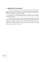
1 Objective of the project
The aim of this project is to build a low-cost head tracking system and mainly to
make a program to govern that system, with the best possible efficiency and capability to
control the mouse pointer of the compute. It must be appropriate for people with motion
disabilities, especially for those with spinal damage.
The scheme of the head tracking is composed of a microcontroller, a camera and a
small simple system of four infrared LEDs forming a rectangular prism, all properly
connected to a computer.
The camera, which is attached on the user´s head, identifies the position of the LED
system, which is placed on top of the computer screen. This information is sent to the
microcontroller, the created software housed in it estimates the position that the camera is
pointing at and therefore which part of the screen the user is looking at. This then
translates it into movement of the mouse pointer and sends it to the computer, moving the
pointer to the estimated point of the screen.
5
2 Components of the project
2.1 LPC1758
As it is described in the NXP LPC17xx User Manual1 that can be found in the
appendix A (p. 3), “the LPC17xx is an ARM Cortex-M3 based microcontroller for
embedded applications featuring a high level of integration and low power consumption.
The ARM Cortex-M3 is a next generation core that offers system enhancements such as
improved debug features and a high level of support block integration”.
Continuing with the description of the User Manual, “the LPC1758 operates at CPU
frequencies up to 100MHz. The ARM Cortex-M3 CPU incorporates a 3-stage pipeline and
uses Harvard architecture with separate local instruction and data buses as well as a third
bus for peripherals. Also includes an internal prefetch unit that supports speculative
branching”.
The peripheral complement of the LPC1758 includes up to 512kB of flash memory,
up to 64kB of data memory, Ethernet MAC, a USB interface that can be configured as
either Host, Device or OTG, 8-channel general purpose DMA controller, 4 UARTs, 2 CAN
channels, 2 SSP controllers, SPI interface, 2 I2C-bus interfaces, 2-input plus 2-output I2Sbus interface, 6 channel 12-bit ADC, 10-bit DAC, motor control PWN, Quadrature Encoder
interface, 4 general purpose timers, 6-output general purpose PWN, ultra-low power RealTime Clock (RTC) with separate battery supply, and up to 52 general purpose I/O pins.
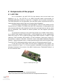
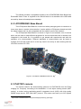
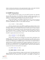
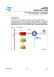
In the case of the used system, the LPC1758 is integrated in the eStick2. The
eStick2, presented in Figure 1, is a low-cost powerful embedded computing platform and
has been developed in the context of the MA23 funded project `Embedded Platforms´ at
the FH Technikum Wien.
Figure 1: eStick2 (Source: [1])
1
2
2
http://www.nxp.com/documents/user_manual/UM10360.pdf
https://cis.technikum-wien.at/documents/bel/3/ess/semesterplan/estick2/estick2.html
6
The eStick2 provides a compatible interface to the LPCXPRESSO Base Board from
Embedded Artist. Power is supplied to the eStick2 board via a standard micro-USB cable
as used by almost all smartphones nowadays.
2.2 LPCXPRESSO Base Board
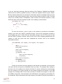
The LPCXpresso Base Board is a useful tool when prototyping work is needed or to
learn more about a certain microcontroller. It works with the LPCXpresso boards and with
the mbed module and it is also compatible with the eStick2 used in this research.
The LPCXpresso Base Board it is shown in Figure 2 and contains a lot of devices
which can be used to make different programs for the microcontroller that is wanted to be
integrated in the board. So it is possible to get started with experiments and with the
operation of a microcontroller. Different standards of communication can be learnt to
manage and use this board and it is the way used in the study to start working with the
LPC1343 and the LPC1758.
Figure 2: LPCXpresso BaseBoard (Source: [2])
3
2.3 PAC7001 camera
The camera used for the head tracking systems is a PAC7001CS from the PixArt
Imaging Inc. Company. According to the datasheet, it is an object tracking sensor (MOT
sensor), a motion tracing application-specific integrated circuit (ASIC) with high quality
CMOS image sensor, DSP and UART protocol. This sensor can track up to four objects
3
http://www.embeddedartists.com/products/lpcxpresso/xpr_base.php
7
smartly with sub-pixel accuracy and output the objects features, like center coordinates or
the object size. These output features of the objects can be transferred to an external
processor, in this case to the LPC1758 microcontroller, through UART interface.
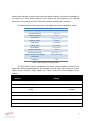
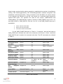
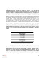
The specifications of the sensor are in the datasheet and are exhibited in Table1.
Specification
Values
Power Supply
Array Elements
Optical Format
Pixel Size
System Clock
PGA Gain
Frame Rate
Scan Mode
Output Interface
UART Baud Rate
Object center coordinate
resolution
Package
3~5V
128 x 96
1/10”
11µm x 11µm
27MHz
16X(24dB)
10~200fps
Progressive
UART
Max Osc / 16
Max 1024*768
CSP
Table 1: Specifications of the PAC7001
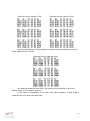
The PAC7001CS can be programmed by setting internal registers via UART and
doing that different parameters can be changed, such as frame rate, exposure control,
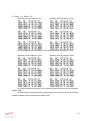
object center resolution, UART speed, etc. Table 2 lists the internal registers of the
camera:
Register
Number
Name
Default
Allowable
Range
Description
0x00
Gain1 (1byte)
0
0~15
Sensor Front Gain
0x01
Gain2 (1byte)
0
0~31
Sensor Global Gain
0x02
Sensor Update
Flag
0
0,1
1: For Sensor Register
Update
0x03
LPF (1byte)
110
110~255
Line per Frame
0x04
Ny (1byte)
1
<LPF
Ny
0x05
IW (2bytes)
640
Max 1024
Image Width
0x06
IH (2bytes)
480
Max 768
Image Height
8
Register
Number
0x07
0x08
0x0E
Name
Threshold
Mode
Power Down
Mode
Dummy byte
number [2:0]
Threshold
(1byte)
Object
Assignment
Mode
Default
136
Allowable
Range
Description
0,1
0
0
0,1
Bit7:0=Manual,1=Auto
Bit6:0
Bit5:0
Bit4:0=Normal,1=Power
down
Bit3:1
Bit[2:0]: Dummy data in
object feature data
1
0-7
40
0~255
Object Threshold
0
0
0:No Assignment Mode
0x0F
Feature Option
Enable Flag
0x7F
0x00~0xFF
0x10
Tracking
Object Number
1
1~4
0x11
Baud Rate
0
0~8
Bit Definition:
0=Disable, 1=Enable
Bit7: Frame header
Bit6:Object aspect ratio
Bit5: Object orientation
Bit4: Object size
Bit3: Object border Y
Bit2: Object Border X
Bit1: Object center Y
Bit0: Object center X
Tracking Object
Number
System clock = 27MHz
0: 27M/1407=19200bps
1:27M/256
2:27M/16
3:27M/703=38400bps
4:27M/469=57600bps
5:27M/234=115200bps
6:27M/117=230400bps
7:27M/59=460800bps
8:27M/29=921600bps
9
Register
Number
Name
Default
Allowable
Range
Description
0x16
SRC
0
-
Skip Report Count
0x18
Aspect
Threshold
0x34
0x00~0xFF
Bit[7:4]:Orientation
Ratio
Bit[3:0]: Reserve
0x1A
YLB
50
0~255
Frame Brightness Low
Bound
0x1B
OALB
8
0~255
Object Area Low Bound
0x1E
Np_H
0
0~3
PXCLK=SYSCLK/2Np;
Np=(Np_H,Np_L)
0x1F
Np_L
3
3~255
PXCLK=SYSCLK/2Np;
Np=(Np_H,Np_L)
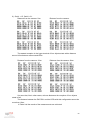
Table 2: Registers of the PAC7001
Gain1 is analog front gain, Gain2 is global gain, is preferable increase Gain1 first
for better SNR. The Gain equation is G1 = (16 + Gain1)/6, Gain1 = 0~15; G2 = (10 +
gain2)/8, Gain2= 0~31. Total Gain (dB) = 20logG1 + 20logG2. The Exposure Line is equal
to (LPF + 1) – Ny and the Exposure time equation is (187*(LPF + 1 –
Ny)*2*Np)/SystemClock. Frame per second (fps) is SystemClock/(187*(LPF + 1)*2*Np).
Then the IW value must be 128*(integral), for example 128, 256… and IH must be
96*(integral) as 96, 192… and the IW:IH ratio must be 4:3. About the OLAB, if the camera
detected an object but his size is under OLAB defined, then PAC7001 will ignore this
object and will not output its features.
So these are the registers that have to be configured in the sensor to make it work
as it is wanted, but to write in this register first it is needed to send the value 0x10 to set
them, and then the register number can be selected and set with the proper value. Once
the setting of the register is finalized, the sensor has to be switched to “Operation mode”,
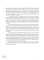
by sending the 0x8D value to the camera, to start the output of the objects features. These
outputs features depend on the 0x0F register, but the normal outputs it is first the header
and then the list of the features of the objects. The header, which is of 4 bytes, is:
0xFF 0x00 0xFF 0xFF
And the normal selected features and their order is:
Flag Byte (1 byte) + Object Flag Byte (1 byte) + X (High Byte) + X (Low Byte) + Y (High
Byte) + Y (Low Byte) + EOB (1 byte)
10
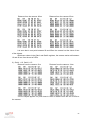
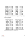
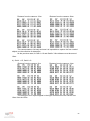
This scheme is repeated with the features of each object. If the sensor is
programed for detecting only one object, the same scheme will be repeated four times but
if the sensor can detect 4 different objects, there will be four different schemes, preceded
by the header. Below are the means or the values that have to be received in each bit of
the parameters Flag Byte, Object Flag Byte and EOB:
Flag Byte
Object Flag Byte
Bit 7: always 1
Bit [5:6]: Condition
0: Invalid Object is not found
1: Trace Trace is O
2: Reserved
3: Reserved
Bit [0:4]: Frame Number
Bit 7: 0
Bit [4:6]: Reserved
Bit [2:3]:
0: Circle object
1: Bar Object
2: Circle-hole Object
3: Bar-hole Object
Bit 1: Reserved
Bit 0:
0: Finish
1: Not Finish
EOB
Bit 7: 0
Bit [4:6]: Object Number
Bit [0:3]: Checksum (Bytes XOR, then Nibbles XOR)
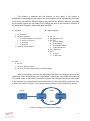
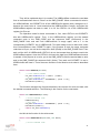
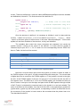
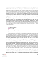
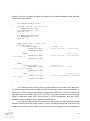
When it is wanted to end with the outputting of the data it is needed to get out of the
“Operation mode” and go back to the “Initial Mode”, sending the value 0x8E to the camera.
This “Initial mode” is the mode in which the registers are configured and is the initial mode
of the camera, but to activate the camera after power on the value 0xEA needs to be sent
to check the sensor. In Figure 3 it is represented the scheme of this activation of modes:
0x8D
0xEA
Power
On
On
Initial
Mode
On
Operation
Mode
On
0x8E
Figure 3: Scheme of the modes of the camera
11
2.4 Set of LEDs
The set of LEDs is the reference that it is going to be taken to move the pointer of
the mouse related to the point that the camera is focusing at. The camera has to be
pointing somewhere inside this set so the program can be able to move the mouse.
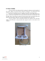
This set is a rectangular prism of 11x8.5x9cm with four infrared LEDs distributed in
pairs, so that there are two LEDs in the front part and the other two in the back part. In the
front part, there is one LED in the lower left corner and the other in the upper right corner
while in the back part the LEDs are in the upper left and the lower right corner.
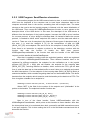
The set, in Figure 4, can be connected via USB to the computer to act it as power
supply of the LEDs and it is also provided with a support to hold it on the screen of the
computer.
Figure 4: Set of LEDs
12
3 State of the Art
Assistive Technology (AT) is a term that covers lots of fields related to the use of
technology in the common life of people with disabilities to make it easier, to perform
functions that otherwise could be difficult or impossible.
AT includes assistive, adaptive and rehabilitative technology and even the process
used in selecting, locating and using them. AT technology can include mobility devices as
wheelchairs, walkers or mobility scooter as well as hardware, software and peripherals that
assist people with disabilities in accessing computers or different kinds of automated
dispositive. All this things promote greater independence to the users, for example, people
who are blind may use software that read texts on a screen with a computer-generated
voice, those who have low vision can enlarge the content of a screen using a special
software, deaf people may use a text telephone or users with speaking problems can
employ devices that speak for them introducing a text via keyboard.
But this research is focused on disabled people with mobility problems, because the
system is addressed to this kind of disability. These people have permanent or transitory
difficulties moving their body, difficulties that can affect from one specific part of their body
to a total paralysis. It can be caused by problems with the tone or the power of the muscles
or problems with mental functions that control sequencing complex movements, the usual
functioning of the central nervous system and the articular system or the muscular system,
which translates in bad regulation of complex voluntary movements. The affected present a
disadvantage in their locomotor system, determined by postural limitations, displacement,
coordination and handling. The causes can be various: hereditary or genetic, occurred
during pregnancy (amniotic), for microbial infections, by accident or trauma, and can be the
origin of spinal cord injuries, traumatic brain injuries, neurological disorders, cerebral palsy,
multiple sclerosis, muscular dystrophy and other diseases source of locomotor disabilities.
Now a review of different tools is going to be done. Of devices on the market
destined to motor disable people but focusing on those tools dedicated to simplify the
access to a computer for these people. Currently, computers have an important role in our
society, and not always people with disabilities can make use of them because of their
illnesses. One of the main fields in assistive technology is to resolve this problem,
developing accessing gadgets to computers to this kind of users, making their lives easier
and allowing them to participate in modern society. These devices are systems for
alternative human computer interaction, like special keyboards, mice, pointers and other
advanced tools.
13
3.1 Keyboards
3.1.1 Expanded Keyboard
It is an adapted USB Keyboard designed with larger keys and high contrast colors.
This keyboard is removable so the user can rest his hands on it. It includes mouse buttons
that can handle the pointer and make clicks as a conventional mouse. It is a keyboard
created for people with motor problems or reduced visibility. Two different types of these
keyboards are exposed in Figure 5.
Figure 5: Expanded keyboards (Source: [3][4])
4 5
3.1.2 One-handed keyboard
This kind of keyboards, like the ones in Figure 6, is designed to be handled with
one hand, even some of them with only two fingers. They have the keys distributed in an
accessible way to be able to reach them easily with one hand. They can also have only a
few keys, less than a normal keyboard, and it is necessary to enter key combinations to
write with them. There are keyboards for both hands or some of them can be
programmable to select the hand to use. It is optimum to people with reduced mobility in
one of the upper extremities.
4
5
http://www.ciapat.org/es/catalogo_producto/teclado-expandido
http://www.geekets.com/2009/02/
14
Figure 6: One-handed keyboards (Source:[5][6])
6 7
3.1.3 Ergonomic Keyboards
They have special form and distribution of the keys to facilitate the insertion of data
as they adapt to the shape of our hands. It reduces wrist movement and the movement of
arms, neck and shoulders. The disposition of the letters can be changed to decrease the
movement of the fingers. They are available for left, right or both hands. They are also
useful for people with problems or pains in the upper body. Two ergonomic keyboards are
collected in Figure 7.
Figure 7: Ergonomic keyboards(Source: [7][8])
6
7
8
9
8 9
http://www.tested.com/tech/280-alternative-keyboard-layouts-why-are-you-still-using-qwerty/
http://carlygoogles.blogspot.com.es/2011/02/has-anyone-invented-one-handed-keyboard.html
http://ounae.com/maltron-keyboard/
http://www.enablemart.com/catalogsearch/result/?q=alternative+keyboards
15
One different ergonomic keyboard it is the Orbitouch keyboard, in Figure 8. It
consists of two special joysticks with eight positions. On the right joystick there are five
letters, numbers or symbols in each position, each character with one color and on the left
joystick there are the five colors. So when it is wanted to select a character, the joystick of
the left hand is moved to the color of the character and the joystick of the right and to the
position where the character is.
Figure 8: Orbitouch keyboard (Source: [9])
10
3.1.4 On-screen keyboard
They are virtual keyboards on the computer which can be controlled by the
common mouse or by a special adapted mouse. Most of them have words or phrases that
are predicted while typing and can stock new words and register the frequency of usage of
the words. Some of the software of these virtual keyboards give the option to select the
position of the characters in the keyboards, which make them more accessible to the
users. There are two on-screen keyboards in Figure 9.
10
http://orbitouch.com/
16
Figure 9: On-Screen keyboards (Source: [10][11])
11 12
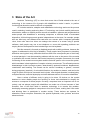
3.1.5 Other types
There are lots of other types of keyboards (Figure 10) so useful to people with
disabilities. There are keyboards to handle with feet, for those who cannot use their hands.
They are larger than the common keyboards to reach each key without problems of space.
There are also keyboards which do not look like keyboards. They have only a few keys and
can be handled with one hand and the combination of these keys can generate the
characters of a usual keyboard. They are suitable for people with problems moving their
arms, shoulders or with back problems
11
http://www.safebit.net/screenshots/safebit-disk-encryption-software-screenshot-virtualkeyboard.html
12
http://www.aureosoft.com/see_and_type.html
17
Figure 10: Different types of keyboards (Source: [12][13][14])
13 14 15
3.2 Mice and joysticks:
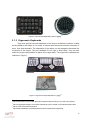
3.2.1 Ergonomic mice and joysticks
The normal design of mice and joysticks can be harmful for people with joint
problems or other similar diseases. Therefore, there are lots of different forms and models
for these devices making them suitable for the people with these ailments. A large variety
of ergonomic mice can be found in the market, as the ones in Figure 11, so the user can
select the comfortable model that reduce or solve his pain.
Figure 11: Ergonomic mice and joysticks (Source: [15][16])
16 17
13
http://www.demotix.com/news/1758185/foot-keyboard-unveiled-gajah-mada-university-disabled-
users/all-media
14
http://www.coroflot.com/erikcampbell/optical-keyboard-keyset
http://walyou.com/jellyfish-keyboard-keyset/
15
16
17
http://www.computer-posture.co.uk/Tennis-Elbow
http://www.fentek-ind.com/zero_tension_mouse.htm#.UiCtZH8rj9M
18
3.2.2 Trackballs
Another device working as a mouse is the trackball. It consists in moving a ball
instead of the whole dispositive of a mouse to move the pointer. Normally it has separated
buttons to avoid unintentional pressing and make clicks like a normal mouse. The roll of
the ball can be done with a hand or just with one finger. That reduces the movement of
hand and arm to control the pointer and makes it perfect for people with wrist problems or
similar ailments. Two types of trackballs are shown in Figure 12.
Figure 12: Trackballs (Source: [17][18])
18 19
3.2.3 Feet mice
There are also mice that can be moved with our feet. They are much appropriated
and specially designed for people with disabilities of the upper limbs. There are different
types of feet handled mice in the market, most of them based in two pedals system,
controlling the pointer with one and the clicking with the other. A different model consists in
a kind of “slipper pointer” moving around like a hand mouse and a series of buttons acting
as the ones in typical mice, including a button for double click or scroll roller. There is even
a mouse for the toes, a small wireless mouse with a clamp which is placed between the big
toe and the second toe. The pointer is controlled moving this mouse and the left and right
click can be done with the big toe and the second toe separately. This variety of feet mice
is gathered in Figure 13.
18
http://www.oucs.ox.ac.uk/enable/index.xml?ID=mice
http://www.assistireland.ie/eng/Products_Directory/Computers/Hardware/Input_Devices/Mice_and
19
_Mouse_Alternatives/Trackballs_/BIGTrack_Supermouse.html
19
Figure 13: Feet mice (Source: [19][20][21])
20 21 22
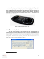
3.2.4 Special joysticks
Joysticks can substitute the mouse and normally less effort is needed to move it
always in a smaller area of movement. It can be used in a lying position which is something
to consider as many patients cannot sit up. Another useful type of joystick is the mouth
controlled joystick (Figure 14). Is an efficient device for those people suffering paralysis
below the neck. They can control the pointer moving this joystick with the tongue or the
mouth, even control the clicking.
Figure 14: Special joysticks (Source: [22][23])
23 24
20
http://www.yankodesign.com/2010/04/07/flip-flop-mouse/
21
http://bilila.com/foot_mouse_slipper_mouse
http://www.funny-potato.com/computer-mice.html
22
23
http://www.turningpointtechnology.com/Sx/AltMice.asp
http://jansapansa.blogspot.com.es/
24
20
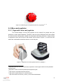
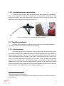
3.2.5 Headpointers and mouthsticks
There are other tools that are less advanced that allow people with disabilities to
make use of computers. These are the headpointers and mouthsticks, consisting in a stick
held by the head or the mouth used to type, move the mouse or touch the screen. One
example of each of these tools is exposed in Figure 15.
Figure 15: Headpointers and mouthsticks (Source: [24][25])
25 26
3.3 Tracking systems
Following other techniques of interaction with computers are described, based on
the tracking of the user focusing on head and eye tracking.
3.3.1 Head tracking
Head tracking technology consists of a device transmitting a signal from on top of
the computer monitor or the laptop and tracking a reflector placed on the user's head or on
special glasses. Acting as a mouse, with a head tracking system a person can control the
cursor movement with the movement of his head. Turning the head left or right, up or
down, the pointer follows that movement on the screen. There are also head tracking
systems in the opposite way, with reflectors placed on the screen and the transmitting
gadget on the head of the users. The gadget and the reflectors can be replaced by infrared
detector camera and infrared lights acting as positional signals and it works as the previous
describe system. Two different devices are presented in Figure 16.
25
http://www.ilcnsw.asn.au/items/6795
26
http://www.cultofmac.com/147506/dutch-inventor-creates-specialized-accessories-for-ipad-userswith-disabilities/
21
Figure 16: Head tracking devices (Source: [26][27])
27 28
To the mouse “click” function there are different possibilities depending on which
head tracking device is used. With some systems peripherals buttons can be added to act
as the common mice buttons, others can interpret that, if the cursor is stationed on an icon
during a predefined time, it means that the user wants to click here or making another
assigned mouse function. It can be combined with blink systems that recognize the blinks
of the user and translate them in mouse buttons functions depending on how it has been
configured.
It is really interesting to combine this head tracking system with the on-screen
keyboards previously described so the user can both control the cursor of the mouse and
write only moving his head.
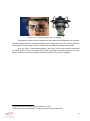
3.3.2 Eye tracking
Eye tracking systems work similar as the head tracking system. Eye tracking is the
process of measuring the point of gaze, where the user is looking, or the movement of the
eyes related to the position of the head. To use this technology to help disabled people to
interact with computers, the system consists of a camera pointing to the user´s eye and a
software that translates the movement of the eye, or the place of the screen where it is
looking at, into movement of the mouse´s pointer. This camera is normally integrated in
special glasses or other devices attached to the head, which also can have included
another camera pointing to the screen to take into account the position of the head relative
to it and coordinate this with the eye camera.
Some examples of eye tracking systems are gathered in Figure 17.
27
http://www.slcentral.com/c/h/r/naturalpoint/trackir/
http://abilityhub.com/mouse/headtrack.htm
28
22
Figure 17: Eye tracking systems (Source: [28][29])
29 30
This system could be used for people who have spinal cord injuries as well as those
with late-stage Parkinson, muscular dystrophy and multiple sclerosis. The eyes are directly
connected to the brain stem so their movement is not affected by spinal cord injuries.
As in the case of head tracking system, the mouse click function can be controlled
by a blink system, much more easily since there is already a camera pointing to the eye.
An also with one on-screen keyboard tool this systems is much more complete.
29
http://www.methoden-psychologie.de/eyetracker_1.html
http://cda.psych.uiuc.edu/matlab_class/Eyelink%20Toolbox%20Home.htm
30
23
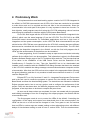
4 Preliminary Work
The implemented low-cost head tracking system consist of a LPC1758 integrated in
the eStick2, a PAC7001 camera and a set of LEDs. All of them are needed to be controlled
to make them work as it is required and this role falls in the microcontroller. Since the
microcontroller is the main part of the system it is very important to know how it works. For
that objective, small programs were built using the LPC1758 addressing various functions
and utilizing its peripherals to interface with the LPCXpresso Base Board
First of all, work began with the LPC1343, the other microcontroller integrated in the
eStick2, which uses the same language (C) as the LPC1758. The LPC1343 is an ARM
Cortex-M3 based microcontroller for embedded applications and has a high level of
integration and low power consumption, as the LPC1758. Both microcontrollers are quite
similar but the LPC1758 has more capacity than the LPC1343, meaning that more different
devices can be controlled with the first than with the second microcontroller. The LPC1343
manages the dispositive integrated in the eStick2, so with the first built programs the 8
LEDs and the accelerometer of the platform can be controlled.
To start programing, first it is needed to setup an open-source tool-chain to develop
software for the eStick2 so it can be accessible. This information is given in the Embedded
Systems Software Design page of the FH Technikum Wien web site. The first step that has
to be taken is the installation of the USB Device Driver and the Download of the
CodeSourcery C Compiler for Arm. Then the OpenOCD has to be downloaded and
installed, which combined with the CMARMJTAG debug firmware that has to be attached
in the LPC1343, establish the debug message communications between computer and the
microcontroller. After that, the CRC tool has to be copied in the appropriate folder following
the given indications, and then it only remains to install an environment to work in C, in this
case the Eclipse-CDT.
Eclipse-CDT is a fully functional C and C++ Integrated Development Environment
and is the tool used to create the programs to control first, the eStick2 and the Xpresso
Base Board, and them the head tracking system. The instructions are followed to install the
Eclipse program and to how to set up a project, and to configure the preferences of this
project. Once this has been done, the different programs can be written. After making the
programs, a few steps have to be done to compile and prove them.
As soon as all these orders are completed, the user can started with the programs
and building knowledge of how the C language, the eclipse program, the eStick2 and the
microcontroller work.
The first program made is one to control the LEDs of the eStick2. Controlling the
configuration of the inputs and outputs from determined pins of the microcontroller, the
LEDs can be set on or off and can be changed of color, from green to red. So functions
that run LEDs in various ways are created, setting on them alternating colors, with different
delays of time between setting on and off one or various LEDs. Then the accelerometer,
24
which is integrated in the eStick2, can be used to make a new program where, depending
on the position of the eStick2, different LEDs will set on.
So with these programs, the registers of the pins and their configuration are known,
which is an important thing prior to establish a communication with the peripherals devices.
The libraries are beginning to be used, how to call them and use them, for example the
LPC13xx library and, inside it, how to work with the GPIO, exploring the possibilities it
gives us.
Once the functioning of the LPC1343 is known and the elements integrated in the
eStick2 controlled by the microcontroller are used, the work with the LPC1758 can be
started, where the programs will be more extensive and complete. The LPC1758 is
integrated in the eStick2 but it does not control the rest of integrated devices in the
platform, however it is connected to the pins of the stick. The eStick2 can be combined
with the Xpresso Base Board, so that the LPC1758 can manage the board and the
elements that are contained in it.
In order to start using the LPC1758 putting the stick in the Xpresso Base Board and
programing in Eclipse, a series of instructions have to be followed to run these programs.
To be able to use and debug an application running on the LPC1758, the LPC1343 has to
be configured as a remote debugger. Once the debug has been flashed on the LPC1343
and the instructions to configure the Eclipse are followed, the programs can be written and
tried.
The LPCXpresso Base Board gives an extensive field testing and different
communication standards can be tested. There are a lot of devices in the board, and each
one uses different communication protocols, so working with these devices makes us learn
how to program these protocols.
A program to manage the 7-segment display is started and the first thing done is
looking at the datasheet of the board to know which pins control the display and which
communication protocol is used in it. The protocol is the SPI, but in the microcontroller the
SSP is intended to be used as an alternative for the SPI interface, so this is used. The pins
of the LPC1758 are configured to access to the display, activate it following the datasheet
and initiate the SSP controller to manage the display. Once that this is done, a program
can be built to make the display do whatever is wanted: count from 1 to 9, countdown,
passing alternative numbers…
Another program made to practice with the LPC1758 and the interfaces is to set up
the USB of the eStick2. One of the micro-USBs of the stick is connected to the LPC1343
and the other is controlled by the LPC1758. To activate the USB interface, the instructions
in the user manual of the LPC1758 have to be followed to introduce the correct commands
to the registers. The bit PCUSB has to be set to power the USB interface and then the
USB clock has to be configured. The corresponding pins of the LPC and their modes have
to be set to control the USB interface and enable the appropriate interruptions for the
objective of the program.
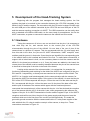
25
5 Development of the Head-Tracking System
Beginning with the program that manages the head tracking system, the first
problem that had to be solved is the connection between the LPC1758 integrated in the
eStick2, the PC and the camera. The connection with the PC had to be done via USB, with
the mini-USB port of the eStick2 controlled by the LPC1758 and one USB port of the PC
and the camera requiring connection via UART. The USB connection can be easily done
with a standard mini-USB-to-USB cable, as the ones used for smartphones, but for the
UART connection, a system to connect the camera to the eStick2 had to be made.
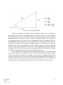
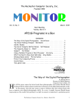
5.1 Hardware
Taking the camera out of its box, one can see that it has six pins. It is necessary to
look what they are for, and connect them to the correct pins of the LPC1758
microcontroller through the pins of the eStick2. On one side of the row of pins of the
camera there is a picture of a square. This pin corresponds with the 3.3 volts supply and,
from this side to the other, the pins are for UART transmission, UART reception, reset,
oscillator and the ground, in that order. Once the pins are identified, the corresponding pins
in the eStick2 have to be localized and linked to the first. To make better connections, a
support with a holed board is built, so the necessary bases to hold the camera and the
eStick2 in the board are soldered on to it. Once the bases are added to the board, the
correct pins of the eStick2 must be carefully identified because the pins of the camera have
to be wired to these pins of the stick in the back of the board.
Looking at the manual of the microcontroller, it is noticed that, for example, the
functions of transmitting and receiving for the third of the UARTs are configured in the pins
P0.0 and P0.1 respectively, so these ports are searched on the pinout of the eStick2. The
UART0, 2 or 3 can be used interchangeably for the communication with the camera, for
this case the UART3 is the chosen option. In the pinout of the eStick2 it is seen that the pin
P0.0 of the LPC1758 corresponds with the pin 13 from the row X3 of the stick and the pin
P0.1 corresponds with the pin 14 from the same row. So the pins of the base of the stick
and the pins of the base of the camera which agree with the mentioned pins are
connected; the transmission pin of the camera with the pin 14 of the stick and the reception
pin of the camera with the pin 13 of the stick. Later, when programming the software, the
register of the pin 13 for UART3 transmission function and the register of pin 14 for UART3
reception mode will be set. Now, the pins for the power supply and the ground must be
localized, which are in the first pins of the row X3 and X4 respectively. It is made the
ground-to-ground connection with the camera and link the 3.3 volts power supplier of the
stick with both the 3.3 volts pin and the reset pin of the camera, to keep it on. These
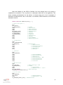
connections are shown in Figure 18.
26
Figure 18: Hardware connections and mounting
5.2 USB Connection
The support required to establish the physical connections is assembled, so the
programming of the software can be started. It begins setting up the USB communication
between eStick2 and PC. On the Internet there are a lot of programs and libraries that can
be used as guide or help to build the needed program. Starting with the initialization of the
USB following the user manual of the microcontroller LPC1758, first it is needed to set bit
PCUSB of the PCONP register, which is the bit 31 of this register, using the LPC17xx
library. Then the USB pins and the corresponding modes are selected. These modes are,
as it is shown in the schematic of the eStick2, the USB_CONNECT, USB_UP_LED,
USB_VBUS, USB_D+ and USB_D-. The USB_CONNECT is the function 1 of the pin 2.09,
1 in the bit 18 of the PINSEL4 register with the lpc17xx_pinsel library. The USB_UP_LED
is the function 1 of the pin 1.18, which is the same as set the bit 4 in the PINSEL3 register,
the USB_VBUS is the function 2 of the pin 1.30, setting the bit 29 of the PINSEL3 register,
the USB_D+ and the USB_D- are both in the PINSEL1 register, they are selected setting
the bits 26 and 28 respectively, USB_D+ is the function 1 of the pin 0.29 and the USB_Dis the function 1 of the pin 0.30. Here is this part of the program in C:
PINSEL_CFG_Type PINSEL_InitStruct;
//LPC_PINCON->PINSEL4 |= 0x1<<18; //USB_CONNECT(2 WAYS TO DO)
PINSEL_InitStruct.Portnum=PINSEL_PORT_2;
PINSEL_InitStruct.Pinnum=PINSEL_PIN_9;
PINSEL_InitStruct.Funcnum=PINSEL_FUNC_1;
PINSEL_ConfigPin(&PINSEL_InitStruct);
27
//LPC_PINCON->PINSEL3 |= 0x1<<4; //USB_UP_LED(2 WAYS TO DO)
PINSEL_InitStruct.Portnum=PINSEL_PORT_1;
PINSEL_InitStruct.Pinnum=PINSEL_PIN_18;
PINSEL_InitStruct.Funcnum=PINSEL_FUNC_1;
PINSEL_ConfigPin(&PINSEL_InitStruct);
//LPC_PINCON->PINSEL3 |= 0x10<<28; //USB_VBUS(2 WAYS TO DO)
PINSEL_InitStruct.Portnum=PINSEL_PORT_1;
PINSEL_InitStruct.Pinnum=PINSEL_PIN_30;
PINSEL_InitStruct.Funcnum=PINSEL_FUNC_2;
PINSEL_ConfigPin(&PINSEL_InitStruct);
//LPC_PINCON->PINSEL1 |= 0x1<<26; //USB_D+ (2 WAYS TO DO)
PINSEL_InitStruct.Portnum=PINSEL_PORT_0;
PINSEL_InitStruct.Pinnum=PINSEL_PIN_29;
PINSEL_InitStruct.Funcnum=PINSEL_FUNC_1;
PINSEL_ConfigPin(&PINSEL_InitStruct);
//LPC_PINCON->PINSEL1 |= 0x1<<28; //USB_D- (2 WAYS TO DO)
PINSEL_InitStruct.Portnum=PINSEL_PORT_0;
PINSEL_InitStruct.Pinnum=PINSEL_PIN_30;
PINSEL_InitStruct.Funcnum=PINSEL_FUNC_1;
PINSEL_ConfigPin(&PINSEL_InitStruct);
// enable PUSB
LPC_SC->PCONP |= 0x1<<31;
Note that the pins can be selected in two different ways. It is declared
PINSEL_InitStruct as a PINSEL_CFG_type structure to select the port, pin and function,
and then PINSEL_ConfigPin is used to set the chosen pin function in the microcontroller.
With the other way, the bit of the wanted function in the LPC1758 with the PINSEL register
is directly set.
Now it is needed to enable the device controller clocks. This is done setting
DEV_CLK_EN and AHB_CLK_EN bits in the USBClkCtrl register, with this name in the
LPC17xx library. The DEV_CLK_EN bit corresponds to the bit 1 in the register and the
AHB_CLK_EN bit to the 4 bit in the register, so they are set. Once that is done, the same
bits in the USBClkSt register has to be checked because it holds the clock availability
status and, if the clocks are set, the software can go ahead with the register access. The
code to enable the clocks:
LPC_USB->USBClkCtrl = 0x1A;
/* Dev clock, AHB clock enable
while ((LPC_USB->USBClkSt & 0x1A) != 0x1A);
*/
Instead of 0x1A, 0x12 could have been put to set the wanted bits, but in examples
in Internet it is done with 0x1A, so that way is followed; the rest of the bits apart from the
two talked about are reserved and not defined. With the “while”, wait until the bits are set.
28
At this time, a kind of initialization of the registers that control the interruptions it is
made, clearing them all and without setting any interruption or giving them any priority. This
registers control the device interruptions and the endpoint interruptions, so in both have to
make this initialization:
LPC_USB->USBDevIntEn = 0;
LPC_USB->USBDevIntClr = 0xFFFFFFFF;
LPC_USB->USBDevIntPri = 0;
LPC_USB->USBEpIntEn = 0;
LPC_USB->USBEpIntClr = 0xFFFFFFFF;
LPC_USB->USBEpIntPri = 0;
Writing a one to a bit in the Interrupt Enable register (USBxxIntEn, xx can be for
Dev, device, or for Ep, endpoint) enables the corresponding bit in USBxxIntSt to generate
an interrupt on one of the interruption lines when set. Writing a one to a bit in the Interrupt
Clear register (USBxxIntClr) clears the corresponding bit in USBxxIntSt, so if an
interruption of the type of the clear bit occurs, it has no effect in the program. The
USBxxIntSt is a register where are located the allowed interruptions that are controlled by
the USBxxIntEn and USBxxIntClr. With the USBxxIntPri, the priority of the interruption can
be controlled, high priority with a 1 and low priority with a 0 in the bit corresponding to the
interruption. The endpoint interruptions are 32, equivalent to 16 endpoints with
transmission and reception, from the bit 0 with Endpoint0 RX to the bit 31 with the
Endpoint15 TX in the registers which control this kind of interruptions. The device
interruptions are 10: ERR_INT, EP_RLZED, TxENDPKT, RxENDPKT, CDFULL,
CCEMPTY, DEV_STAT, EP_SLOW, EP_FAST, and FRAME, from the bits 9 to 0
respectively in the registers that control these interruptions. These will be later explained.
Continuing with the initialization, only ACK and not NAK from the endpoints can
provoke an interrupt. This function does that:
USBHwNakIntEnable(0);
Inside this function:
void USBHwNakIntEnable(U8 bIntBits)
{
USBHwCmdWrite(CMD_DEV_SET_MODE, bIntBits);
}
What it does is write the value bIntBits (0 in this case) in the command Set Mode
(CMD_DEV_SET_MODE == 0xF3) of the SIE. The SIE is the Serial Interface Engine and it
handles the transfer of data between the endpoint buffers in EP_RAM and the USB bus, so
it controls what is read from and is written in the endpoints buffers. The functions of this
29
block include: synchronization pattern recognition, parallel/serial conversion, bit stuffing/destuffing, CRC checking/generation, PID verification/generation, address recognition, and
handshake evaluation/generation. These commands, as the Set Mode, are used to access
to the registers and functions of the SIE, and consist on a command code followed by
optional data bytes. Two registers are used for this access, USBCmdCode and
USBCmdData. The USBCmdCode register is divided in CMD_PHASE, from bit 8 to 15,
and CMD_CODE or CMD_WDATA, from bit 16 to 23. In the CMD_PHASE there are 3
possibilities:
`Write´ with the value 0x01
`Read´ with the value 0x02
`Command´ with the value 0x05
If in the CMD_PHASE field there is `Read´ or `Command´, then the field name is
CMD_CODE and it contains the code for the command, and if there is `Write´, the field is
CMD_WDATA and it contains the command write data. The SIE commands are collected
in Table 3:
Command name
Recipient
Code(Hex)
Data Phase
Set Address
Configure Device
Set Mode
Read
Current
Frame Number
Read
Test
Register
Set Device Status
Get Device Status
Device
Device
Device
Device
D0
D8
F3
F5
Write 1 byte
Write 1 byte
Write 1 byte
Read 1 or 2 bytes
Device
FD
Write 1 byte
Device
Device
FE
FE
Write 1 byte
Read 1 byte
Get Error Code
Read Error Status
Select Endpoint
Device
Device
Endpoint xx
FF
Read 1 byte
FB
Read 1 byte
xx (same as the Read
1
endpoint)
(optional)
40 + xx
Read 1 byte
Select Endpoint/
Endpoint xx
Clear Interrupt
Set
Endpoint Endpoint xx
Status
Clear Buffer
Selected Endpoint
Validate Buffer
Selected Endpoint
40 + xx
Write 1 byte
F2
Read
1
(optional)
None
FA
byte
byte
Table 3: SIE commands
30
They will be explained when it is needed. The USBCmdData contains the read data
from a command when there is `Read´ on the CMD_PHASE. When a command is write in
the USBCmdCode, the CCEMPTY bit of the USBDEvIntSt register (bit 4) changes to a 0,
because the reset value is 1 and means that the USBCmdCode is empty, and when the
USBCmdData register has data to read, it is full, the CDFULL bit of the USBDevIntSt
register (bit 5) is set.
The operation mode for these commands is, first, clear CDFULL and CCEMPTY
bits with USBDevIntClr register. Then, in the USBCmdCode register, put the wanted
command code in the CMD_CODE and the sequence 0x05 (Command) in the
CMD_PHASE field, and wait until USBCmdCode is empty again, with a 1 in the
corresponding CCEMPTY bit of USBDevIntSt. This part always must be done and, when
this is accomplished, clear CCEMPTY again. If the purpose is read, the same command
code has to be put, as well as the sequence 0x02 (Read) in the CMD_PHASE field. Then
wait until the bit 5 of USBDevIntSt (CDFULL) is set, that means there is data to read in the
USBCmdData register, clear the CDFULL and save the data from USBCmdData wherever
is wanted. If the purpose is to write, put in the CMD_WDATA field the wanted data to write
and in the CMD_PHASE the sequence 0x01 (Write). Then wait until CCEMPTY is set in
USBDevIntSt and clear it. There are some functions in the libraries to do what is described
here:
static void USBHwCmd(U8 bCmd)
{
// clear CDFULL/CCEMTY
LPC_USB->USBDevIntClr = CDFULL | CCEMTY;
// write command code
LPC_USB->USBCmdCode = 0x00000500 | (bCmd << 16);
Wait4DevInt(CCEMTY);
}
This function manages the first part described, the common for write and read, with
the wanted command selection. The following is the function for the read mode:
static U8 USBHwCmdRead(U8 bCmd)
{
// write command code
USBHwCmd(bCmd);
// get data
LPC_USB->USBCmdCode = 0x00000200 | (bCmd << 16);
Wait4DevInt(CDFULL);
return LPC_USB->USBCmdData;
}
And this is the function for the write mode:
static void USBHwCmdWrite(U8 bCmd, U16 bData)
{
// write command code
31
USBHwCmd(bCmd);
// write command data
LPC_USB->USBCmdCode = 0x00000100 | (bData << 16);
Wait4DevInt(CCEMTY);
}
In these three functions, the field “bCmd” is for the wanted command code in byte
and the “bData” field is for the byte data to write in the selected command. The last is the
one used in the function USBHwNakIntEnable(0) to use the Set Mode command as it has
been shown before.
After this preparation process of the USB pins and interruptions, encompassed in
the USBHwInit() function of the usbhw_lpc library, it is the turn of the interrupt handlers.
With the function USBHwRegisterDevIntHandler(HandleUsbReset) of the usbhw_lpc library,
the DEV_STAT interruption can be enabled, which corresponds with the bit 3 in the
USBDevIntXx registers. This interruption occurs when USB bus is reset, USB suspends
change or when connect change event happens. Now, following some internet examples,
the same of enabling the device interruption is done, but with the endpoints interruptions:
USBHwRegisterEPIntHandler(0x00, USBHandleControlTransfer);
USBHwRegisterEPIntHandler(0x80, USBHandleControlTransfer);
With these functions, the endpoints interruptions for the EP0 and the EP8 are
enabled, as well as the EP_SLOW interruption, which is the slow endpoint interruption for
endpoints with no priority, and established USBHandleControlTransfer as a handler on
endpoint transfers. Once this is done, the endpoints have to be enabled and configured.
Configure an endpoint means to realize it, to reserve a buffer space for the endpoint and to
establish a maximum packet size for the endpoint. When this is done, wait for setting the
EP_RLZED bit in the USBDevIntSt register, which means that the endpoint is correctly
done, and then clear it. This is done with the function USBHwEPRealize(idx(endpoint nº),
wMaxPacketSize) and then the endpoint is enabled with the function USBHwEPEnable(idx,
TRUE), which uses the Set Endpoint Status command to write in the wanted endpoint to
enable it. Both functions are gathered in the function USBHwEPConfig, and to set the
wanted endpoints the order to put in the program is:
USBHwEPConfig(0x00, MAX_PACKET_SIZE0);
USBHwEPConfig(0x80, MAX_PACKET_SIZE0);
Following the examples, to finish this initialization of the USB, a function of the usb
control library is needed to be used, to register a callback for the handlers of the
interruptions. This function is:
USBRegisterRequestHandler(REQTYPE_TYPE_STANDARD, USBHandleStandardRequest,
abStdReqData)
32
Now the initialize of the USB is finished, but more things have to be done to
establish the connection. First, a pointer to a descriptor block has to be registered. This
block contains all descriptors for the device. In internet there are a lot of examples of
descriptor of USB devices, and, in this case, it is needed a USB connection, so the device
descriptor used is:
static const U8 abDescriptors[] = {
/* Device descriptor */
0x12,
DESC_DEVICE,
LE_WORD(0x0110),
0x00,
0x00,
0x00,
MAX_PACKET_SIZE0,
LE_WORD(0xFFFF),
LE_WORD(0x0001),
LE_WORD(0x0100),
0x01,
0x02,
0x03,
0x01,
//
//
//
//
//
//
//
//
//
//
//
//
// configuration
0x09,
DESC_CONFIGURATION,
LE_WORD(0x22),
0x01,
0x01,
0x00,
0x80,
0x32,
// wTotalLength
// bNumInterfaces
// bConfigurationValue
// iConfiguration
// bmAttributes
// bMaxPower
// interface
0x09,
DESC_INTERFACE,
0x00,
0x00,
0x01,
0x03,
0x00,
0x00,
0x00,
bcdUSB
bDeviceClass
bDeviceSubClass
bDeviceProtocol
bMaxPacketSize
idVendor
idProduct
bcdDevice
iManufacturer
iProduct
iSerialNumber
bNumConfigurations
//
//
//
//
//
//
//
bInterfaceNumber
bAlternateSetting
bNumEndPoints
bInterfaceClass = HID
bInterfaceSubClass
bInterfaceProtocol
iInterface
// HID descriptor
0x09,
DESC_HID_HID,
// bDescriptorType = HID
LE_WORD(0x0110),
// bcdHID
0x00,
// bCountryCode
0x01,
// bNumDescriptors = report
DESC_HID_REPORT,
// bDescriptorType
LE_WORD(sizeof(abReportDesc)),
// EP descriptor
0x07,
DESC_ENDPOINT,
INTR_IN_EP,
// bEndpointAddress
0x03,
// bmAttributes = INT
LE_WORD(MAX_PACKET_SIZE),// wMaxPacketSize
33
10,
// bInterval
// string descriptors
0x04,
DESC_STRING,
LE_WORD(0x0409),
// manufacturer string
0x0E,
DESC_STRING,
'L', 0, 'P', 0, 'C', 0, 'U', 0, 'S', 0, 'B', 0,
// product string
0x12,
DESC_STRING,
'P', 0, 'r', 0, 'o', 0, 'd', 0, 'u', 0, 'c', 0, 't', 0, 'X', 0,
// serial number string
0x12,
DESC_STRING,
'D', 0, 'E', 0, 'A', 0, 'D', 0, 'C', 0, '0', 0, 'D', 0, 'E', 0,
// terminator
0
};
If the USB device is wanted as interface for a mouse or a joystick, the “interface”
field of the descriptor block has to be changed. So the function that registers the pointer to
the block is:
USBRegisterDescriptors(abDescriptors)
Following some internet examples, now some handlers for requests have to be
registered. Let‟s see this registers:
// register HID standard request handler
USBRegisterCustomReqHandler(HIDHandleStdReq);
// register class request handler
USBRegisterRequestHandler(REQTYPE_TYPE_CLASS,HandleClassRequest,
abClassReqData);
// register endpoint
USBHwRegisterEPIntHandler(INTR_IN_EP, NULL);
// register frame handler
USBHwRegisterFrameHandler(HandleFrame);
In the first register, HIDHandleStdReq tries to service any HID specific request and
the USBRegisterCustomReqHandler function guides the program to it as a callback function.
The second function registers a callback for HID class request handler with
HandlerClassRequest as handler and REQTYPE_TYPE_CLASS to define the class type.
With the function USBHwRegisterEPIntHandler and with INTR_IN_EP, the endpoint 8 and 1
are enabled, but give a NULL callback function. The USBHwRegisterFrameHandler function
34
enables the FRAME interrupt which corresponds with the bit 0 of the USBDevIntXx
registers, and this interruption occurs every 1ms. It is used for isochronous packet
transfers and the function gives the HandleFrame as callback function too.
Once the handlers are prepared, the USB has to be connected. This is done with
the function USBHwConnect(TRUE), so that with TRUE, a 0 is written in the connect bit (bit
0) of the Set Device Status command. It means that the CONNECT pin go high, so the
connection with the USB Bus is done. When the connection is established and all is
prepared, a loop is built to call the USB interrupt handler continuously:
while (1) {
USBHwISR();
}
The USBHwISR() function, which is the USB interrupt handler, is included in the
usbhw_lpc library.
With all of this, the program of the USB connection is finished. The describe
functions developed are in the different libraries, such as usbstdreq, usbinit, usbhw_lpc or
usbcontrol, and the handlers are described in the actual USB connect program.
5.2.1 USB Program: Joystick
To check that the USB connection works properly, a program is built that will help
later in the aim of moving the pointer of the mouse with the PAC7001 camera respect to
the set of LEDs. A mouse joystick is going to be configured with the joystick of the
LPCXpresso Base Board, managed by the LPC1758 and connected to the computer via
USB. The previous USB program is used, but it must be adapted to act as a mouse
attending to the movement of the Board joystick.
One of the changes is in the descriptor of the USB device is in the interface field of
the descriptor, the byte of interface number has to be changed to 0x01, because now the
mouse function is needed, and the byte of interface protocol must be 0x02 because it
corresponds to Mouse protocol. After changing that, the initialization of the USB stack is
the same, as well as the function to register the pointer to the device descriptor, the
function to register the HID standard request handler, the one for the class request handler
and the function that registers the endpoints. A report descriptor of the data is added when
the USB is used as an interface for a mouse, and it is used in the handler of standard
request. This report is generated by a HID descriptor tool program, which can generate
descriptors for other purposes or protocols. Another function that has to be changed is the
handler of the frame interruptions, to provide a real mouse reports. This handler is the
responsible of the movement of the cursor in the computer. It is needed to introduce a
different data to the endpoint buffer (computer) from the one it previously had. This data is
the displacement of the mouse, along the X axis, the Y axis and the press button of the
35
mouse. These are defined as a structure called HIDDMouseInputReport and the variables
are bmButtons, bX and bY. The final structure of the definition is:
typedef struct {
unsigned char bmButtons;
/// Bitmap state of three mouse
buttons.
signed char bX;
/// Pointer displacement along the X
axis.
signed char bY;
/// Pointer displacement along the Y
axis.
} __attribute__ ((packed)) HIDDMouseInputReport;
Once the structure is defined, it is necessary to initialize it, and it is done with the
function HIDDMouseInputReport_Initialize(HIDDMouseInputReport *report), where
“*report” is the name given to the structure, in this case “MouseInputReport”. This function
equals to 0 the three variables of the structure, so they are initialized.
The variables that control the cursor movement are prepared, but remain the
joystick controls. Looking at the pinout of the eStick2, it is seen that the joystick is
controlled by the pins 2.0, 2.1, 2.2, 2.3 and 2.4 in the corresponding function GPIO Port.
Here in Table 4 is the list of the controls:
Command
Function
Press Joystick
GPIO Port 2.0
Joystick Right
GPIO Port 2.1
Joystick Up
GPIO Port 2.2
Joystick Left
GPIO Port 2.3
Joystick Down
GPIO Port 2.4
Table 4: Functions for the joystick program
Now that it is known which pins control the joystick, a function to check is made, in
the FIOPIN register of the port 2, the bits corresponding with these pins. The current state
of digital pins can be read from the FIOPIN register so, if the joystick is moved to the right,
the bit 1 of the FIOPIN register of the port 2 is set and, if it is moved to the left, the bit 3 of
this register is set. The bits from 0 to 4 in the FIOPIN register are checked and then put
them in order in one byte, invert this byte and pass it with an AND operator through a mask
of 0xff. Finally it is obtained the command sent by the joystick in a one byte variable. The
order of the bits from this variable, from the bit 0 to the bit 4, are joystick right, joystick left,
joystick down, joystick up and select joystick, so depending on which of these bits are set,
the movement of the joystick is known and so the movement that the pointer has to do.
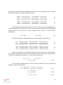
The described function is:
36
void JoystickRead(int *pi_JoystickState)
{
int i_up, i_dn, i_l, i_r, i_sel;
int i_State;
i_sel = (LPC_GPIO2->FIOPIN>>0) & 1;
i_r = (LPC_GPIO2->FIOPIN>>1) & 1;
i_up = (LPC_GPIO2->FIOPIN>>2) & 1;
i_l = (LPC_GPIO2->FIOPIN>>3) & 1;
i_dn = (LPC_GPIO2->FIOPIN>>4) & 1;
i_State = (i_sel<< 4) | (i_up<<3) | (i_dn<<2) | (i_l<<1) |(i_r);
i_State = (~i_State) & 0xff;
*pi_JoystickState = i_State;
}
In the variable appears “*pi_JoystickState”. In this case the name of the variable is
“i-JoystickState”, the state of the joystick, where it is moved to. To know which of this is, it
is compared with a series of defined parameters. Each of these parameters correspond
with a state of the joystick, so that the JOYSTICK_CLICK parameter has the value 0x10,
the JOYSTICK_UP parameter has 0x08 and so on, so it is easy to see which of these
parameters has the same value, the same bit set as the variable “i-JoystickState”. Once
the state of the joystick is identified, the correct movement in the X axis or in the Y axis to
the cursor is needed to be sent. As it was said before, this movement is controlled by the
variables of the HIDDMouseInputReport structure, a value to these variables is given
depending on the state of the joystick. The X axis is the horizontal axis, and the Y is the
vertical axis and the movement of the cursor for each movement of the joystick is 10 units,
positives when moved right and down and negatives when moved left and up. The
comparison with the parameters and the corresponding send of movement orders are in a
loop together with the USB interrupt handler, to call them continuously.
One of these blocks of comparison and send movement orders, for the UP state of
the joystick is:
if(i_JoystickState & JOYSTICK_UP)
{
MouseInputReport.bY = -10;
MouseInputReport.bX = 0;
MouseInputReport.bmButtons = 0;
}
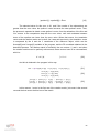
So finally the program is done. It is needed to integrate the eStick2 in the XPresso
Base Board, make relevant connections and at the end, the pointer of the mouse can be
moved with the joystick of the Board. It is concluded that the USB connection works and
the instructions for the mouse too, and they will be needed for the main program of the
head tracking system.
37
5.2.2 USB Program: Send/Receive characters
Now another program for the USB communication is done, to receive characters via
USB from the keyboard of the computer and to send these characters back to the
computer and show them in the screen, something that will be helpful later. The same
scheme as the used to do the joystick program is followed, with the same initialization of
the USB stack. Then comes the USBRegisterDescriptor function, to set a pointer to the
descriptor block of the USB device. In this case, the descriptor of the USB device is
different from the descriptor of the joystick program, because the USB is not an interface
for a mouse protocol, is only a bridge to exchange data. So instead of define the mouse
protocol, is needed to define which endpoints are used to send the data and which to
receive it. There are a lot of examples in the Internet of these types of descriptors and, in
this case, it is used the endpoint 0 TX for the transmission of data via USB
(BULK_OUT_EP) and endpoints 1Rx and 0 Rx for the reception of data (BULK_IN_EP).
Once there is an instruction to register a pointer to the descriptor, continue with the
function that
calls the function to handle the USB
class request.
USBRegisterRequestHandler is the function that calls the handler of the USB class
request, and this handler is HandleClassRequest.
After that, is needed to continue with the endpoints handlers, which are registered
with the function USBHwRegisterEPIntHandler. Three different handlers have to be
registered for different endpoints; the endpoint for the notifications as in the joystick
program (INT_EN_EP = 0x81) with null handler, the endpoint for the outgoing data
(BULK_OUT_EP), selecting BulkOut as handler, which controls the FIFO, get the data
from it, write this data into an intermediate buffer to send it later to an endpoint and control
the NAK interruptions. For the endpoint of the incoming data (BULK_IN_DATA) BulkIn is
selected as handler, which controls the getting data from an intermediate buffer. This buffer
has data from the endpoint which transmits, and the handler put the data into a FIFO. The
form to register a handler for an endpoint is:
USBHwRegisterEPIntHandler(U8 bEP, TFnEPIntHandler *pfnHandler)
Where “bEP” is the field for the number of the endpoint and “*pfnHandler” is the
pointer to the handler. The endpoints handler functions are:
USBHwRegisterEPIntHandler(INT_IN_EP, NULL);
USBHwRegisterEPIntHandler(BULK_OUT_EP, BulkOut);
USBHwRegisterEPIntHandler(BULK_IN_EP, BulkIn);
Now is turn of the frame handler. Select USBFrameHandler with the
USBHwRegisterFrameHandler, which points at this handler as frame handler. After that,
the interruptions have to be activated when both, successful and NAK transactions occurs
in an input endpoint. This is done setting the bit 5 in the Set Mode command and this is
done with the function:
38
USBHwNakIntEnable(U8 bIntBits)
Where “bIntBits” is the byte wanted to be written or the bits wanted to be set in the
SET MODE command. With USBHwNakIntEnable(INACK_BI), where INACK_BI is (1 << 5
= 0x20), the bit 5 is set and these desired interruptions are activated. Once the
interruptions are enabled, it is needed to initialize the VCOM port, which is initialize the
transmission FIFO and the reception FIFO, initialize his pointers. This is done with the
function VCOM_init() and all the FIFO instructions are located in the library “serial_fifo”.
When it is switched on, the USB bus is connected with the function
USBHwConnect(TRUE). After that, a loop is started with the getting of characters from the
computer keyboard and then the put back of the character on the USB bus, which can be
the same character or this one treated.
For the getting of characters there is the function VCOM_getchar(), which takes the
characters in order from the Rx FIFO queue. This FIFO is filled by the BulkIn handler with
the characters pulsed in the keyboard. The VCOM_getchar function returns to the main
program the first character of the FIFO queue and advanced the FIFO pointer to the next
character, all of these aided by the program “fifo_get” from the library serial_fifo. After
calling this VCOM_getchar function and store the obtained character in a variable, this
treated character is needed to be put back to the computer to show it. This is done with the
function VCOM_putchar, where the character to show is an input variable. Inside the
function, with the fifo_put order, the character is put in the Tx FIFO queue to send it to the
endpoint and advance in the Tx FIFO pointer to continuing filling the queue. In this case,
the treatment that is applied to the received character is adding 1 to his value, so if the „a‟
button of the keyboard is pushed, the program will send back a „b‟. Put the VCOM_putchar
function in an IF loop where the program gets in if the variable is not EOF:
while (1) {
c = VCOM_getchar();
if (c != EOF) {
VCOM_putchar(c + INCREMENT_ECHO_BY );
}
}
To see the characters back in the computer a hyper terminal is used. In some
Windows systems the hyper terminal is not included, so a free version can be downloaded,
as Hyper Terminal Private Edition. For the proper functioning of the hyper terminal and the
detection of the USB cable from the USB device of the LPC1758 in the eStick2 to the
computer, when it is required, Windows has to be directed to a special file which is found in
examples in internet, “usbser.inf”. With this file, Windows creates an extra COMX port for
the mentioned connection that can be opened in the hyper terminal. To see the treated
characters that are sent back from the program, as well as the typed characters, is
necessary to configure the hyper terminal. The hyper terminal should be set to append line
39
feeds to incoming line ends and to echo typed characters locally, so the typed characters
can be compared with the treated ones and check that the program works.
5.3 UART Connection
Once the USB connection is done, is turn of the UART connection. As it was done
with the USB, the manual of the LPC1758 is followed to establish the connection. It is
needed to remember that the physical links are done with the UART3 pins, so it is
necessary to configure the UART3 registers to set up well the connection.
First the bit PCUART3 in the register PCONP has to be set up to turn on power to
UART3. This bit is the number 25 of the register, and it is saved in the parameter
PCUART3_POWERON, so power on is done with the instruction:
LPC_SC->PCONP |=
PCUART3_POWERON
Then the peripheral clock for the UART3 is needed to be selected, which is in the
PCLKSEL1 register. The corresponding bits for the PCLK_UART3 are the bits 18 and 19 of
this register and depend on the values of these bits, the clock is set in one way or another
with respect to the core clock(CCLK). So that, a 00 means the PCLK is equal to CCLK/4, a
01 means PCLK= CCLK, a 10 PCLK= CCLK/2 and 11 PCLK= CCLK/8. In this case the
clock is set to a ¼ of the core clock, so first “clean” the PCLK_UART3 bits of the
PCLKSEL1 register and let them with a 00 value:
LPC_SC->PCLKSEL1 &= ~(PCLK_UART3_MASK);
LPC_SC->PCLKSEL1 |= (0 << PCLK_UART3);
Now the UART3 pins have to be selected in the correct function, setting them in the
PINSEL register. The pin who controls the UART3 transmission is the P0.0 and the one for
the UART3 reception is the P0.1, so both are in the lower half of the Port 0 that means this
functions are controlled by the PINSEL0 register. In both cases, the wanted function to
operate the pins as UART3 transmission and reception respectively is the function 2. So
the value 10 (2 in hexadecimal) is put in the characteristic bits of each pins, bits 0 and 1 for
pin P0.0 and 2 and 3 for pin P0.1, in the PINSEL0 register. These bits can be cleared first
to ensure the values are correctly written in the register:
LPC_PINCON->PINSEL0 &= ~0x0f;
LPC_PINCON->PINSEL0 |= 0x2<<0; //TxD3
LPC_PINCON->PINSEL0 |= 0x2<<2; //RxD3
The lines of communication are setting, now the format of the data character that
passes through them has to be defined. This is done in the register U3LCR and it is
controlled with the LCR command over LPC_UART3. In this register, the length of the
40
send/receive word can be decided, enabled or not the parity and selected the type of it or
enabled or not the access to Divisor Latches with the Divisor Latch Access Bit (DLAB). The
Divisor Latch is divided in DLL, which is his least significant byte, and the DLM, which is his
most significant byte, and the full value is used to divide the PCLK in order to generate the
baud rate clock. The DLAB must be 1 to access to these DLL and DLM register and select
a value for them, and must be 0 to enable interruptions and realize other functions. The bit
description of the LCR is in Table 5:
Bit
Symbol
Value
Description
1:0
Word Length Select
00
01
10
11
5 bit character length
6 bit character length
7 bit character length
8 bit character length
2
Stop Bit Select
0
1
1 stop bit
2 stop bit
3
Parity Enable
0
1
Disable parity gen.
Enable parity gen.
5:4
Parity Select
00
01
10
11
Odd parity
Even parity
Forced “1” stick parity
Forced “0” stick parity
6
Break Control
0
1
Disable break transm.
Enable break transm.
7
DLAB
0
1
Disable access to DL
Enable access to DL
8:31
-
-
Reserved
Table 5: Description of the LCR
In this case, the data character is programed of 8 bits, 1 stop bit, no parity and
setting the DLAB, so the value to introduce in the U3LCR register is 0x83 and the
command used to do it is:
LPC_UART3->LCR = 0x83;
// 8 bits, no Parity, 1 Stop bit, DLAB=1
Now the DLL and DLM values have to be selected to have the wanted baud rate.
The general formula to estimate the baud rate of the UART3 is ([30], p. 313):
[1]
41
Where PCLK is the peripheral clock, U3DLM and U3DLL are the baud rate divider
registers and DivAddVal and MulVal are the fractional baud rate generator specific
parameters. In this case, the division between these two parameters is 0 because they
have not an assigned value, the reset value for DivAddVal is 0 and for MulVal is 1, and so
have no impact in the baud rate. The PCLK of the UART3 is defined as ¼ of the core
clock, and the baud rate is a chosen value, the value of DLM and DLL can be obtained,
where the DLM is the result of the final division and the DLM is the modulo, the integer
reminder of this division, which is:
[2]
The commands used in the program to find the values for the U3DLM and U3DLL
registers and to give these values to these registers are:
// PCLK_UART3 is being set to 1/4 of SystemCoreClock
pclk = SystemCoreClock / 4;
Fdiv = ( pclk / 16 ) / baudrate ;
// Set baud rate
LPC_UART3->DLM = Fdiv / 256;
LPC_UART3->DLL = Fdiv % 256;
Where “baudrate” is the wanted baud rate for the UART3 communication and is an
input variable for the whole program of UART3 initialization. Once the baud rate of the
UART3 is selected, it is needed to enable the UART3 Rx and Tx FIFOs for proper UART
operation in transmission and reception. This is done in the U3FCR register, where setting
the bit 0 enable both Rx and Tx FIFOs, setting the bit 1 reset the Rx FIFO and setting the
bit 2 reset the Tx FIFO. So the hexadecimal value 7 is assigned to the register U3FCR to
enable all, and also in the U3LCR register the DLAB is disabled to allow enable
interruptions, but maintaining the rest of the setting bits in the previous access to this
register:
LPC_UART3->LCR = 0x03;
LPC_UART3->FCR = 0x07;
// 8 bits, no Parity, 1 Stop bit DLAB = 0
// Enable and reset TX and RX FIFO
With this, the program to initialize the UART3 is finished. The described functions
are collected in one to do the initialization, and is in this one where “baudrate” is an input
variable:
void UART3_Init(int baudrate)
As with this function, a communication via UART can be started with a device, now
it is necessary to build functions to send and receive characters over UART3. The register
that provides information about the existence or not of data to receive, or the possibility of
sending a character in the UART3, is the U3LSR register. The main bits of this register, to
carry out these purposes, are the Receiver Data Ready (RDR) and the Transmitter Holding
42
Register Empty (THRE). The RDR bit is the bit 0 of the U3LSR register and is set when the
UART3 receiver FIFO is not empty, when the U3RBR holds an unread character, and it is
cleared when the UART3 receiver FIFO is empty. The U3RBR register is the top byte of
the UART3 Rx FIFO, it contains the oldest received byte and can be read via the bus
interface, but to do it the DLAB must be 0. The THRE bit is the bit 5 of the U3LSR register
and is set when the U3THR register is empty and clear when U3THR contains valid data,
the reset value is 1. The U3THR is the top byte of the UART3 Tx FIFO, is the newest
character in the Tx FIFO and can be written via bus when the DLAB is 0. Writing in the
U3THR register causes the data to be stored in the UART3 Tx FIFO.
Looking what is just described, to do the program to send characters over UART3,
the THRE bit and the U3THR register are used, and for the program to receive data is
used the RDR bit and the U3RBR register. For the receive data program, first the RDR bit
of the U3LSR register has to be checked, until it is set, what means the receiver FIFO is
not empty and there is something to read. When this is the case, the receiver character
has to be read from the U3RBR and stored in a variable, to use it as output of this program
to receive. The name of this function is UART3_Getchar:
char UART3_Getchar()
{
int c;
while( (LPC_UART3->LSR & LSR_RDR) == 0 );
c = LPC_UART3->RBR;
return c;
}
For the transmission program, the bit THRE has to be checked until it is set, what
means the U3THR register is empty, so the Tx FIFO is empty to receive data to send.
When this bit is set, the character wanted to send over the UART3 can be written in the
U3THR. This character is an input variable of this sending program, in this case named “c”.
The name of the program is UART3_Sendchar:
void UART3_Sendchar(int c)
{
while( (LPC_UART3->LSR & LSR_THRE) == 0 );
LPC_UART3->THR = c;
}
With the function for the initialization of the UART3 and these two functions, to send
and receive characters via UART3, a program can be built to communicate with the
PAC7001 camera. These last functions are needed to first configure the camera, sending
the parameters for the camera registers, and second, to receive the information from what
the camera can see.
43
5.4 Camera configuration and communication
Now start with the camera, the configuration and the communication between it and
the LPC1758. For knowing how to work with the PAC7001, the datasheet of it is followed.
To configure the camera in the wanted way, a series of commands are sent in a specific
order, but first of all, the mode of the camera has to be changed. When the camera is
power on, it starts in an “Initial mode” as a default mode. The first thing that has to be done
is send the command “Check device”, which is done sending the hexadecimal value 0xEA.
With this command, the chip of the camera starts, is a kind of password for it. Then, all the
wanted registers can be set up, or read, but for this, a combination of instructions has to be
followed. After the work with the registers is done, the camera has to be switched to the
“Operation mode”, sending the data 0x8D to the camera. Once the PAC7001 has entered
this mode, it starts to output the objects features; it “sends” determined characteristics of
the object that capture to the microcontroller. In this case, “send” means that the
microcontroller takes this information from the camera, with the previously described
function UART3_getchar. To get out of this “Operation mode” and the output of data from
the camera, 0x8E is sent to the PAC7001 and it will go back to the “Initial mode”. The
sending of data from the microcontroller to the camera is done with the function
UART3_sendchar, to work with the registers. Now, in Table 6 the described process to
access to the modes of the camera is presented, and the instructions that have to be
followed to set or read the registers of the PAC7001:
Command Order
Command Content
Sensor ACK
0xEA
“Tracking V01”
0x10 + Register Number + 0x10
Register Value
Read Register
0x11 + Register Number
Register Value (High Byte
First)
Switch to “Operation 0x8D
0x8D
Mode”
Check Device
Set Register
Table 6: Set camera modes
As it is shown, to set a register, first 0x10 has to be sent to the camera, following by
another message with the number of the register wanted to be set, and then another
message with the value wanted to be introduced in the selected register. Notice that the
camera generates an ACK with every command it receives. Looking at the system to
setting a register, a function is made to do it directly, CameraSet (char RegNum, char
RegValH, char RegValL), where RegNum is the number of the register to set, RegValH is
the high byte value for those registers that have two value bytes and RegValL is the low
value for these registers or the unique value for those register with only one byte value. In
the function, the first step is send a 0x10 to the camera, to indicate that a register is going
44
to be set, and then continuing with the sending of the RegNum, RegValH and RegValL
values with the UART3_sendchar function to select the registers and the proper values.
But the camera needs a time to process the information and the messages cannot be sent
one after the other without waiting a little, so the function Delay (int secs) is used. The field
secs is for a number which is multiplied by 1000, and then the function entered in a loop
that finish when reach this obtained number, from 0 adding 1 each iteration:
void Delay (int secs)
{
int i = 0;
while ( i <= (secs*1000))
{
i++;
}
}
So with this function, a time is given to the camera to process the information,
putting it just after every UART3_sendchar function. Once all the commands required to
set a register are sent, to finish with the CameraSet function, the Rx FIFO queue is read
with the UART3_Getchar function, where must be the ACK message generated by the
camera, to clear this queue and thus completed the function. Here is the complete
CameraSet function:
void CameraSet (char RegNum, char RegValH, char RegValL)
{
int f;
UART3_Sendchar(0x10);
Delay(300);
UART3_Sendchar(RegNum);
Delay(300);
if (RegValH != 0)
{
UART3_Sendchar(RegValH);
Delay(300);
}
UART3_Sendchar(RegValL);
Delay(300);
f = UART3_Getchar;
f = UART3_Getchar;
}
Finally, the function to set the registers of the camera is completed, so this process
can start, but first, the previous initialization has to be done. The program that is going to
be done now is to configure the camera and check if it works, showing the received data
from the camera in the hyper terminal, as the treated characters are shown in the USB
program for exchange data. So the same process for initialize the program is used, with
the USBInit, the pointer to the descriptor of the USB device, the register of the handlers for
the endpoints, frame interruptions and class request, the enable of the NAK interruptions in
45
the incoming transactions, the VCOM_init and the final connection of the USB with the
USBHwConnect function. As soon as this part is finished, starts the configuration of the
camera. The first part is initializing the UART connection for the LPC1758, in this case with
the UART3 interface, to establish communication with the camera. The initialization is done
with the function UART3_Init and the baud rate is set to 19200 bps, which is the default
baud rate of the camera. Now, the connection is realized, and the sending of data from the
microcontroller to the camera can start. As is said in the datasheet, the first command is
the “Check Device” command, sending the value 0xEA. This is done with the function
UART3_Sendchar and then, the camera has to send back to the microcontroller the ACK
“TrackingV01”, as a signal of the start of the camera. It is easy to check that the mentioned
message is received, just every character over the UART3 have to be read, with the
UART3_Getchar function, stored in variables and shown these variables in the hyper
terminal with the VCOM_putchar function. But that cannot be done in the main program,
only as a prove. So to remove the “TrackingV01” message from the receive FIFO queue, a
loop is made, that will not end until the last character of the sentence is read, the “1”, which
is a 49 in ASCII terms:
UART3_Sendchar(0xEA);
h = UART3_Getchar();
while (h != 49)
{
h = UART3_Getchar();
}
When the ACK from the PAC7001 is received, the program can continue with the
set of the registers described in the section about the camera. As it was said previously,
with the CameraSet function, the number of the register has to be introduced as an input
variable, as well as the value wanted to be introduced on the register. The configuration of
the registers starts with the Gain1 and Gain2, and first they are set to 10 and 0
respectively. Then come the LPF and the Ny registers, which are programmed with the
values 118 and 1, as recommend the datasheet. After that, the register 0x1E (Np_H) is set
to 0 and the register 0x1F (Np_L) to 3. The datasheet said that the register 0x02 must be
set to 1 for sensor register update after the registers 0x00, 0x01, 0x03, 0x04, 0x1E or 0x1F
have changed, and these registers are which have just been configured, so now the
register 0x02 is put to 1. The registers IW and IH have two value bytes, and they are set to
the maximum value permitted, 1024 for the IW register, which is 0x04 for the high byte and
0x00 for the low, and 768 for the IH register, 0x03 for the high byte and 0x00 for the low
one, and they meet the requirement of IW:IH = 4:3. Continuing with the registers and
following the datasheet, the value 0x88 is introduced to the register 0x07, to put the
threshold mode in automatic and set it without dummy data, and the Threshold register is
set, which value register is 0x08, to 40, as is recommended. In the register 0x0E, the set
value is 0, which means there is no assignment mode, and for the selection of the objects
46
features to receive, the 0x0F register is used. It is set to 0x93, so the reception of the frame
header, the object size, the object center Y and the object center X is enabled. In Table 7
is present the Register 0x0F and the meaning of its bits.
Register 0x0F (1Byte), Feature Option Enable Flag (0:Disable, 1:Enable)
Bit7: Frame Header
Bit6: Object Aspect ratio
Bit5: Object Orientation
Bit4: object Size
Bit3: Object Border Y
Bit2: Object Border X
Bit1: Object Center Y
Bit0: Object Center X
Table 7: 0x0F register of the camera: select the features to receive
The register 0x10 determines the number of tracking objects. In the case of the
Head Tracking System, 4 benchmarks are needed, 4 points with which calculate the
position of the camera with the POSIT algorithm, so the value of this register must be 4.
Then the 0x16 register is set to 0 and the 0x1A register to 50, as is recommended for the
frame brightness low bound. The register 0x1B refers to the Object Area Low Bound
(OALB), where, if the camera detected an object but his size is under the defined OLAB,
the PAC7001 will ignore it and will not output the features of this object. If this value is set
too large, an object will be easily ignored operating at a long distance, but if the value is
too small, less than 3, the accuracy will be lost when interpolating higher coordinate
resolution (1024x768) and the noise will be easily came in. The suggested value in the
datasheet is 3, so this value is the used one.
Finally, the registers setting is finished, but once this was done and the entire
program was completed, nothing is received from the camera; there were not features of
the objects in the hyper terminal. That was because of the baud rate. At first the baud rate
was very low, to configure the registers of the camera, but to the outputting of the features
of four objects and the collecting of them by the LPC1758, a higher baud rate is needed.
So, afterwards setting the register 0x1B, the register 0x11 has to be set, because this
register controls the baud rate. After several tests with different baud rates, finally is prove
that the best value for it is 115200bps, which corresponds with the value 5 of the register
0x11, so this value is introduced to the register. For the proper operation of the connection
between camera and microcontroller, the UART3 of the LPC1758 has to be re-initialized,
but with the new baud rate value. Once the baud rate is set correctly, the camera has to be
changed from the “Initial mode” to de “Operation mode”, to start with the output of the
objects features. To do this, with the function UART3_Sendchar the value 0x8D is sent to
47
the camera. In this mode, the registers cannot be changed and the camera starts to
“produce” the features of the objects that it captures.
The process which corresponds with the Initial mode and the configuration of the
camera registers is ended, now starts the Operation mode part, with the collection of data
from the objects, the adequate treatment of them and their shown in the hyper terminal.
First, two pointers are declared, pointing to a buffer; one of these pointers is pbGet and the
other pbPut. In this buffer the collected data from the camera will be stored, with the pbPut
pointer go over the buffer and saving the data coming from the camera on it and the pbGet
pointer taking this data to showing it in the hyper terminal. Apart from these pointers, a
structure is declared to store the features of the detected objects when they have been
selected and identified from the buffer. This structure contains all the types of features that
the camera could send of each object. As the camera will send information of four different
objects, four of these structures are needed, which will be saved in an array of four
elements called “Data”. The structure is:
typedef struct {
U16 BX;
U16 BY;
U16 Size;
U8 FlagByte;
U8 ObFgBy;
U8 EOB;
} obj;
These components of the structures in each one of the four elements of the array
“Data” have to be initialized. This is just put their values equal to 0, and this is done with
the function DataInit, putting the “Data” array as input of the function. After this is done, an
infinite loop is started with the instruction “while (1)” and inside this loop, all the treatments
that the data need are done, from the collection of them from the camera to the final
display of them in the hyper terminal.
The first step is filling the previously mentioned buffer through the pbPut pointer.
The first value output from the camera is assigned to the pointer, with the function
UART3_Getchar, so that in the first position of the buffer that value is stores, and then the
pointer is advanced one position, to point to the next position of the buffer. This process is
done continuously until the buffer is empty, whose size is 64, so it stop when pbPut reach
the position 64 of the buffer. When it happens, pbPut has to be initialized to the first
position of the buffer and start working with the data from the buffer. At the time to work
with the buffer, the beginning of the group of data that forms the features of the four objects
has to be identified. It is easy to think that now it starts at the first position of the buffer, but
it is necessary to deal with cases in general, where the buffer can start to store the data
from the middle of the group of data, from the features of the third object, for example. The
header is the key. Searching the header in the buffer, the group of data will be found in
48
order, first the features of the first object, then the features of the second, of the third and
finally of the fourth object, so the header has to be localized. It is know that the header is
composed by four bytes, which are 0xFF, 0x00, 0xFF and 0xFF, in that order, so this
succession of bytes has to be found to localize the features of the four objects in order. For
doing that, a variable is declared and equated to the pbGet pointer, to go with it across the
buffer which contains the data from the camera, in search of the header. In a “While” loop,
this variable is compared with 255, the decimal value of 0xFF, the variable pointer is
advanced, the new value is compared with 0, from 0x00, advanced it again, compared with
255 and so on, until these four values are found followed, and then is when the loop is left.
Once the header is located, as the program is for general cases, the buffer has to be
checked to see if all the wanted information, with the data from the four objects, is on it.
The size of the buffer is 64, and each object has 9 bytes of information, with the header are
40 bytes that must be together. The pbGet pointer is pointing to the first byte of the header
after the search of the succession, so the current position of the pointer plus 40 is
compared with the 64 bytes of size of the buffer, to check that everything is in the buffer.
Now that is sure that the features of the objects are all followed and together in the buffer,
starts their identification, recognition of what type of feature is. In the datasheet is shown
the order in which the camera output the information of each object, and it is collected in
Table 8:
Received Bytes from the camera in order of arrival
Flag Byte
Object Flag Byte
X (High Byte)
X (Low Byte)
Y (High Byte)
Y (Low Byte)
Size (High Byte)
Size (Low Byte)
EOB
Table 8: Order of arrival of bytes from the camera
As the sequence of arrival is known, the data is going to be identified and stored as
it is needed. To do that, there is the ProcessData function. In this function, the mentioned
“Data” array and the pbGet pointer are introduced as input variables where, as it was said,
pbGet is pointing to the first byte of the localized header in the buffer. Inside the function,
the first step is to remove the bytes of the header and advance along the buffer, until the
pointer is on the first byte of information of the first object. In this moment, a loop is started
to take every feature of each object and put it in the Data array, each object in one of the
elements of the array and every type of characteristics in their corresponding variables of
49
the structures, in each element of the array. So the loop goes from 1 to 4, going through
the elements of the “Data” array and, following the order of arrival, storing the features in
the correct variable and advancing through the buffer. The complete ProcessData function
is the following:
void ProcessData(obj *object, unsigned char *buffer)
{
unsigned char *tmp;
tmp = buffer;
head[0]
head[1]
head[2]
head[3]
=
=
=
=
*(tmp++);
*(tmp++);
*(tmp++);
*(tmp++);
for( j=0; j<4 ; j++)
{
object[j].FlagByte = *(tmp++);
object[j].ObFgBy = *(tmp++);
object[j].BX = (*(tmp++) << 8);
object[j].BX |= *(tmp++);
object[j].BY = (*(tmp++) << 8);
object[j].BY |= *(tmp++);
object[j].Size = *(tmp++) << 8;
object[j].Size |= *(tmp++);
object[j].EOB |= *(tmp++);
}
Now the characteristics of the objects are correctly localized and stored, if the user
wants to see them, just have to show them in the hyper terminal with the function
VCOM_putchar, but have to treat the stored data.
The data containing in the variables in each element of the “Data” array are
represented in decimal code, and it needed to be translated into hexadecimal code to a
better presentation and interpretation of the information. To do this, the TreatData function
is used, with the byte of data to treat as input variable. In the function, first the bits from 7
to 4 of the byte are taken and transformed into hexadecimal value, and then the same is
done with the bits from 3 to 0 of the byte. The process is the following:
void TreatData (unsigned char x)
{
unsigned char b = x >> 4;
VCOM_putchar(b + ((b < 10) ? '0':('A'-10)));
b = x & 15;
VCOM_putchar(b + ((b < 10) ? '0':('A'-10)));
}
50
With this method, if the numbers are bigger than 9, which are letters in hexadecimal
code, the corresponding letter is shown in the hyper terminal, with the ASCII code. This
function is applied to every byte of data that is wanted to be shown with the
VCOM_putchar. How to display the data in the hyper terminal can be easily modified and,
in this case, the features are shown separated between them with a space, and one object
per line, so there are rows of objects and columns of features.
Before the loop of the program is finish, the pgGet pointer has to be reinitialized,
pointing again to the first element of the buffer, so the process of filling the buffer and
taking the wanted data can be started again.
5.4.1 Camera Test-Program: Obtained Data.
The program that can communicate with the PAC7001 camera and show in the
hyper terminal the data outputting by the camera is built. First of all, a capture of the data is
exposed in Figure 19, with the features of the objects captured by the camera, and they
are going to be analyzed, to understand what they mean:
Figure 19: Example of data from the camera in the hyper terminal
Here there are three blocks of the data sent by the camera, represented in the
hyper terminal, with hexadecimal numbers and distributed in columns of coordinate X (BX),
coordinate Y (BY), EOB (EO), Flag Byte (FB), Object Flag Byte (OF) and Size (SZ) of each
one of the objects captured by the camera, which are every row. The BX values must be
between 0 and 1024 in decimal numbers, and the BY value between 0 and 768. It is
noticed that, for example, 467 in hexadecimal is 1127 in decimal, or that 41B is 1051,
which are greater than 1024 and 768 respectively. This problem is tried to be solved
51
discovering the reason of this behavior of the values for BX and BY, and a sweep is done
with a light from the beginning to the end of both X and Y axis of the field of view of the
camera, to see the variation of the X and Y coordinates. Finally, is figured out that the most
representative bit of the low byte of X and Y is always set to 0, never change and it is not
taken into account in the final values of X and Y, so there are some “jumps” that have to be
fixed later in the program, for a proper operation. That is the reason of this high values for
the X and Y coordinates in this capture.
In the Flag Byte field (FB) is represented the number of frame and if the object is
found, if the camera can capture the correspond object. The bit 7 is always 1, the 6 and 5
represent the capture of the objet (01) or not (00) and the rest of bits represent the frame
number. It is seen that all the objects of the same frame have the same FB byte, and the
following frames have not continue the progression of numbers because during the
treatment of data, or because one frame is not completely in the buffer, frames are lost in
the middle.
With the Object Flag, the shape of the object can be known, and if the frame is
finished or not. The bit 7 is always 0 and bits 3 and 2 represent the shape of the object: 00
means circle object, 01 bar object, 10 circle-hole object and 11 bar-hole object. In this
case, there are circle objects. The last bit represent if the frame is finish, 1 says not and 0
says yes, and as is seen, in the first 3 objects is represented that the frame is not finish,
and the last one has a 0 in their last bit, which means the frame is finished. The rest of bits
are reserved.
Now this data will be seen changing the registers of Gain 1 and Gain 2, which are
previously set to 10 and 0 respectively, to test which combination is better in matter of
distance of the camera from the set of LEDs and better reception of the four objects. To do
these checking, the camera is placed at a height of 7.5cm, 4 cm displaced from one side of
the set of LEDs and pointing to this set, so the camera is put more or less focusing at the
center of the triangular prism that form the set. The measure starts with the camera at 5 cm
from the front side of the prism and it will be distanced 5 cm by 5 cm, searching to receive
all the objects and finished when it cannot be possible.
The maximum value for the Gain 1 is 15 and for Gain 2 is 31. The comparisons
start with the pair Gain1=10, Gain2=0, the recommended value in the datasheet, and then
these values will be varied:
52
1) Gain1 = 10, Gain2 = 0.
Distance of the camera: 5 cm
Distance of the camera: 10 cm
At a distance of 5cm the camera can only capture 2 objects, but when the distance
is 10cm the four objects can be captured by the camera.
Distance of the camera: 15cm
Distance of the camera: 20 cm
In both cases the four objects still appears in the data from the camera show at the
hyper terminal.
53
Distance from the camera: 20cm
Distance from the camera: 25cm
It is seen that in one point between 20 and 25cm the camera lost the vision of two
of the objects.
With these values in the Gain1 and Gain2 registers, the camera works well between
10 and 20 cm from the set of LEDs.
2) Gain1 = 10, Gain2 = 15.
Distance from the camera: 5cm
Distance from the camera: 10cm
The four objects appear in a point close to 10cm of distance from the set of LEDs to
the camera.
54
Distance from the camera: 15cm
Distance from the camera: 20cm
The camera starts to fail and just can capture 3 objects at these distances, so is not
needed to check more
The proper distance for this value of the Gain1 and Gain2 is around 10 cm, what is
not good for the wanted purpose.
3) Gain1 = 10, Gain2 = 31
Distance from the camera: 5cm
Distance from the camera: 10cm
At around 10cm of distance between the camera and the LEDs the features of the
four wanted objects are started to be seen in the hyper terminal.
55
Distance from the camera: 15cm
Distance from the camera: 20cm
The camera starts to fail early and now it is impossible to capture the four needed
objects, so the collection of data stops.
As the previous case, for Gain1= 10 and Gain2= 31the distance must be around
10cm.
4) Gain1 = 15, Gain2 = 0:
Distance from the camera: 5cm
Distance from the camera: 10cm
The features of four objects appear in the hyper terminal when the camera is at
10cm from the LEDs.
56
Distance from the camera: 15cm
Distance from the camera: 20cm
Now at these distances, is still seeing in the hyper terminal the features of the four
LEDs captured by the camera
Distance from the camera: 25cm
In a distance between 20 and 25cm, the receiving of the features of two of the
objects stops, so the measure stops too.
In this case of configuration of the Gain1 and Gain2 registers, a valid range is
obtained from 10 to a bit more than 20cm.
57
5) Gain1 = 15, Gain2 = 15.
Distance from the camera: 5cm
Distance from the camera: 10cm
It is seen again that the reception of four objects starts at a distance of 10cm.
Distance from the camera: 15cm
Distance from the camera: 20cm
It is observed that the features of four objects cannot be received, so the collection
of data stops.
As other cases, the system with the registers set in that way could only work with a
distance between LEDs and camera of about 10cm
58
6) Gain1 = 15, Gain2 = 31.
Distance from the camera: 5cm
Distance from the camera:
The wanted reception in the hyper terminal of four objects starts with a distance
around 10cm between camera and LEDs.
Distance from the camera: 15cm
Distance from the camera: 20cm
It is seen that, like in other cases, at these distances the reception of four objects
starts to fail.
The distance between the PAC7001 and the LEDs with this configuration cannot be
more than 10cm.
In Table 9 all the results of the measurements are collected:
59
Gain1
Gain2
Range of distances between PAC7001
and LEDs to captures 4 objects
10
10
10
15
15
15
0
15
31
0
15
31
~ 10-20 cm
~ 10 cm
~ 10 cm
~ 10-20 cm
~10 cm
~10 cm
Table 9: Distances between PAC7001 and the LEDs to capture 4 objects, according to the values of
Gain1 and Gain2
With these tests it is seen that the best option for the Gain1 and Gain2 registers of
the camera is set the Gain2 register to 0 and the Gain1 to 10 or 15. That gives a maximum
distance between the camera and the set of LEDs a little bit more than 20cm.
It is observed that in every measure, at 5 cm the camera can only capture 2
objects, that is because of the field of view. The field of view (Figure 20) is the part of the
world that is visible by the camera and, in this case, according to the datasheet, the field of
view is 64 degrees in diagonal.
Figure 20: Field of view
With this angle, two right triangles can be formed, one upper and other lower, with a
horizontal line crossing the angle and dividing it in two angles of 32 degrees. Knowing this
angle and one of his sides of the right triangle, the rest of the sides can be easily obtained
(Figure 21):
60
Figure 21: Right triangle and sides
There is an angle of 32 degrees and the adjacent side is 5 cm, so there is a
hypotenuse of 5.89 cm and, continuing operating, an opposite side of 3.12 cm is obtained.
So, being the field of view a rectangle, with 4:3 ratio (array elements 128 x 96 in the
datasheet) and, as the angle of view is in diagonal, being the distance from the center of
the rectangle to each of his vertex 3.12 cm, a rectangle of 4.99x3.74 is obtained. This is no
compatible with the front square of the set of LEDs, which is a square of 11x8.5. However,
if the same operations are done with an adjacent side of 14 cm, which is the 5 cm of
distance of the camera to the LEDs plus 9 cm of depth of the prism of LEDs, a distance
from the center of the rectangle to one vertex of 8.74 is obtained, which means that the
rectangle is 14x10.5 which is more than the rectangle of LEDs of the back part. So these
two LEDs of the back part are the objects that the camera captures.
In the case of 10 cm of distance from the camera to the LEDs, the result of the field
of view of the camera is a rectangle of 10x7.5. That not fix with the fact of the four objects
can be seen when the camera is at a range of 10 cm, but it is probably because of the
measure is realized from the front of the camera, which is approximately at a distance of 1
cm from the sensor, plus measurement errors and a wider angle of view. For example, with
this centimeter of more distance, all the LEDs can be in the field of view of the camera.
61
5.5 POSIT Algorithm
The program for seeing the data outputting from the camera has been seen, and
now the POSIT algorithm is going to be done, to work with these data with the objective of
moving the mouse pointer according to them.
The process of develop the POSIT algorithm is well explained by DeMenthon and
Davis [34], which paper is collected in the appendix B, and this explanation is followed to
build the POSIT program. The part of the main program which contains the POSIT
algorithm has to start after the ProcessData function, after the obtaining and orderly
storage of the data from the buffer. There are 6 different steps described in the mentioned
study of the POSIT, the first of them is the preliminary step, which consists in writing a
matrix composed by the vectors that connect a reference point with the rest of the points.
In this case there are four points, four objects that the camera can capture and output their
features, and these objects correspond with the four LEDs in the set of LEDs. So what it is
done is select one of these LEDs as reference point, and measure the distance with the
rest of the LEDs, in this manner a matrix with dimension 3x3 is obtained, where each row
is the vector of this distance from the reference point to each one of the rest of LEDs. The
set of LEDs is, according with the coordinate system of the camera, a rectangular prism of
11x8.5x9 cm, with the distribution of the LEDs appearing in Figure 22:
Figure 22: Set of LEDs and the position of them
The red spots are the places of the LEDs, and the LED 1 is selected as the
reference point, so the distance vector to the LED 2 is (11,8.5,0), the vector to the LED 3 is
(11,0,9) and the vector to the LED 4 is (0,8.5,9) and the rows of the wanted matrix, the A
matrix, are:
62
A=
Once the A matrix is formed, his pseudoinverse matrix has to be taken, the B
matrix. The pseudoinverse matrix equation is:
A+ = (AT A)-1 AT = B
[3]
The result of that operation is
B=
Once we have the two matrixes, the epsilon0 has to be initialized, as it is said in the
paper. There are 3 epsilon0, as vectors in the A matrix, and they have to be equalized to 0
at the beginning of the loop of the POSIT algorithm. When this is done, first both the image
vector x and image vector y have to be computed with 3 coordinates, one for each one of
the objects that there are, excluding the reference object. The name for these vectors in
this case is Xim and Yim, and the form of the coordinates that make them is:
Ximi = Xi (1 + epsilon0i) – X0
Yimi = Yi (1 + epsilon0i) – Y0
[4]
Where X0 and Y0 are the BX and BY features of the reference object and X i and Yi
the same features of the rest of the object, with i = {1, 2, 3} corresponding with LED 2, LED
3 and LED 4 respectively. But in this point there is a problem, because is not known to
which of the four LEDs correspond the features sending by the camera as the first object,
the same happened with the second, third and fourth object. So before starting with the
image vectors, the data has to be identified, which of the objects outputting by the camera
refers to the reference LED and which to the others, following the order shown in the cube
image. For doing that, it is know that the object center coordinate resolution of the camera
is max 1024*768, which means that the maximum value of the coordinates for X is 1024
and for Y 768, with a range between 0 and these numbers. So the center of the system,
the point which is in the middle of the set is the point (512,384) and the coordinates for X
and Y for each object captured by the camera are referred to this center. The camera
always must be pointing inside the cube of LEDs, so the central point of the coordinate
system must be placed somewhere between the four LEDs. In this manner, a LED is
placed in each one of the quadrants of the coordinate system (Figure 23), so it will be easy
to identify the quadrant and the correspondent LED:
63
Figure 23: Quadrants in the camera´s reference system and the LEDs on it
As it is shown in the picture, to identify the LED 1, the reference object, it is needed
to find the object outputting from the camera which features BX and BY match with the
condition described for the Quadrant III and select this object as reference. The same
search for the LED 2 in the Quadrant I, the LED 3 in the Quadrant II and the LED 4 in the
Quadrant IV, to maintain the order of vectors following for the matrix A. Now there is a
problem with the data received as the X and Y coordinates of the different objects, as it
was described previously. The most significant value of the low byte of X and Y does not
change, it is always 0, and it must not be taken into account to store the value of the
coordinates. So it is needed to skip it and “put together” the two resulting parts of both X
and Y variables, the part of the left of the bit, and the part of the right. This is done with the
following commands, obtaining the wanted and correct values in the variables Xvar and
Yvar:
U16 Xvar = 0, Yvar = 0, a = 0, b = 0;
a = (Data[cont].BX & 127);
b = (Data[cont].BX >> 1);
Xvar = b ^ a;
a = (Data[cont].BY & 127);
b = (Data[cont].BY >> 1);
Yvar = b ^ a;
Finally, values for the coordinates that will be in the expected ranges are obtained;
from 0 to 1024 for X coordinate and from 0 to 768 for the Y coordinate. Once the data is
64
treated, it can be compared to place the objects in the different quadrants and estimate
which LED is the studied:
for (cont=0; cont<4; cont++)
{
U16 Xvar = 0, Yvar = 0, a = 0, b = 0;
a = (Data[cont].BX & 127);
b = (Data[cont].BX >> 1);
Xvar = b ^ a;
a = (Data[cont].BY & 127);
b = (Data[cont].BY >> 1);
Yvar = b ^ a;
while ((Xvar != 0 ) | (Yvar != 0))
if (Xvar<= 512 ){
if (Yvar <= 384){
Xcenter[0] = Xvar;
Ycenter[0] = Yvar;
}
else {
Xcenter[3] = Xvar;
vector matrix A
Ycenter[3] = Yvar;
}
}
else {
if (Yvar <= 384){
Xcenter[2] = Xvar;
distance vector matrix A
Ycenter[2] = Yvar;
}
else {
Xcenter[1] = Xvar;
vector matrix A
Ycenter[1] = Yvar;
}
}
// Quadrant III
// Match with LED 1, reference LED
// Quadrant VI
// Match with LED 4, third distance
// Quadrant II
// Match with LED 3, second
// Quadrant I
// Match with LED 2, first distance
}
It is noticed that the first two blocks of data taken from the buffer of the data from
the camera have values that are different than the expected, even solving the problem of
the unset bit. That causes a bad assign of objects with LEDs and it have to be solved for
their later use in the POSIT algorithm. To do that, a variable controls the times that the
buffer is filled with useful data, and the part of “LEDs assignations” and the POSIT
algorithm are not started until this variable is greater than 2.
Once that the objects from the camera are matched with the LEDs in the way that is
wanted, continues with the image vectors. There is already described the formula for the
image vectors Xim and Yim, where each term of the vector depends of the coordinates of
65
the reference object and the coordinates of each of the rest of the object in order, as it was
described previously. To obtain the whole vectors:
Xim[0] = (Xcenter[1]*(1 + epsilon0[0])- Xcenter[0]);
Xim[1] = (Xcenter[2]*(1 + epsilon0[1])- Xcenter[0]);
Xim[2] = (Xcenter[3]*(1 + epsilon0[2])- Xcenter[0]);
[5]
Yim[0] = (Ycenter[1]*(1 + epsilon0[0])- Ycenter[0]);
Yim[1] = (Ycenter[2]*(1 + epsilon0[1])- Ycenter[0]);
Yim[2] = (Ycenter[3]*(1 + epsilon0[2])- Ycenter[0]);
[6]
After obtaining these image vectors Xim and Yim, they have to be multiplied by the
matrix B. Multiplying B and the vector Xim a vector called I is obtained, and multiplying B
and the vector Yim the result is a vector called J, both of them, of course, with 3
coordinates.
I = B * Xim
J = B * Yim
[7]
The way in that these operations are done in the program is the following:
I[0] = B[0][0]*Xim[0] + B[0][1]*Xim[1] + B[0][2]*Xim[2];
I[1] = B[1][0]*Xim[0] + B[1][1]*Xim[1] + B[1][2]*Xim[2];
I[2] = B[2][0]*Xim[0] + B[2][1]*Xim[1] + B[2][2]*Xim[2];
[8]
J[0] = B[0][0]*Yim[0] + B[0][1]*Yim[1] + B[0][2]*Yim[2];
J[1] = B[1][0]*Yim[0] + B[1][1]*Yim[1] + B[1][2]*Yim[2];
J[2] = B[2][0]*Yim[0] + B[2][1]*Yim[1] + B[2][2]*Yim[2];
[9]
Where can be seen how is obtained each term of the vector I and J. These vectors
are necessary to get later the vectors for the rotation matrix and the scale of the projection.
This scale is s and it is the result of (s1 + s2)/2, where s1 and s2 are:
s1 = (I · I)1/2
s2 = (J · J)1/2
s = (s1 + s2)/2
[10]
So is needed to operate with the I and J vector to obtain the s1 and s2 factors and
finally the scale of the projection:
s1 = I[0]*I[0] + I[1]*I[1] + I[2]*I[2];
s2 = J[0]*J[0] + J[1]*J[1] + J[2]*J[2];
[11]
s1 = sqrt(s1);
s2 = sqrt(s2);
[12]
s = (s1 + s2)/2;
[13]
66
Now it is time to get the i and j vectors, necessary to obtain the k vector and, with
the three of them, get the rotation matrix. The i and j vectors are just the division between
the coordinates of the I vector and the s1 factor and the coordinates of the J vector and the
s2 factor respectively, and the k vector is the cross-product of these i and j vectors:
i[0] = I[0]/s1;
i[1] = I[1]/s1;
i[2] = I[2]/s1;
[14]
j[0] = J[0]/s2;
j[1] = J[1]/s2;
j[2] = J[2]/s2;
[15]
k[0] = (i[1] * j[2]) - (i[2] * j[1]);
k[1] = (i[2] * j[0]) - (i[0] * j[2]);
k[2] = (i[0] * j[1]) - (i[1] * j[0]);
[16]
After that, following the paper, the z coordinate of the translation vector is going to
be taken. The x and the y coordinates of this vector are the x and y coordinates of the
reference object, and the z coordinate is obtained dividing the camera focal length by the
scale of the projection, the parameter s. In the PAC7001 camera, according to the
datasheet, the focal length must be 1024, value which is stored in the variable Focal_L,
and to get the z coordinate, named as Z0, it is done:
Z0 = Focal_L/s;
[17]
Now new epsilons have to be computed, and the vector that contains these new
epsilons is called epsilon1. Each of the components of the vector is formed from the
vectors of the matrix A, the vectors of distance of the LEDs with respect to the reference
LED, LED number 1. Thus, the first element of the epsilon1 vector is formed from the
distance vector of the LED2, the second element of the vector from the distance vector of
the LED3, and the third element from the distance vector is formed from the distance
vector of the LED4. To complete the obtaining of the epsilon1, each of these vectors have
to be multiplied by the k vector and the result divided by the Z0 coordinate previously
obtained. Finally, the wanted vector is achieved. That is how it is done in the program:
epsilon1[0] = 1/Z0 * (A[0][0]*k[0] + A[0][1]*k[1] + A[0][2]*k[2]);
epsilon1[1] = 1/Z0 * (A[1][0]*k[0] + A[1][1]*k[1] + A[1][2]*k[2]);
epsilon1[2] = 1/Z0 * (A[2][0]*k[0] + A[2][1]*k[1] + A[2][2]*k[2]);
[18]
At this moment, epsilon0 and epsilon1 vectors are in the program. Now the epsilon0
is subtracted to the epsilon1, term by term, and done the absolute value of the subtraction,
to check if the final results of each operation are greater or not than an error value
previously defined.
67
|epsilon1[i] – epsilon0[i]| < Error
[19]
The selected value for this error is 0.1 and if the results of the subtractions are
greater than the error value, the epsilon1 vector becomes the new epsilon0 vector. Thus,
the process is repeated to obtain a new epsilon1 vector, from the estimation of the Xim and
Yim vectors to the comparison step with the error value, until each subtracts between
terms of the epsilons are lower than the error value. When that occurs, the translation
vector and the rotation matrix can be built. As it was said previously, the translation vector
is composed by the X and the Y coordinate of the reference object, which are the
Xcenter[0] and Ycenter[0] variables of the program, and the Z0 coordinate obtained in the
described process. The rotation matrix is formed by the row vectors i, j and k, and when
the rotation matrix must be perfectly orthonormal, these vectors have to be renormalized,
which is:
k‟ = k / |k|
j‟ = k‟ x I
[20]
And this is obtained in the program in this way:
mod = sqrt(k[0]*k[0] + k[1]*k[1] + k[2]*k[2]);
[21]
krot[0] = k[0]/mod;
krot[1] = k[1]/mod;
krot[2] = k[2]/mod;
[22]
jrot[0] = (krot[1] * i[2]) - (krot[2] * i[1]);
jrot[1] = (krot[2] * i[0]) - (krot[0] * i[2]);
jrot[2] = (krot[0] * i[1]) - (krot[1] * i[0]);
[23]
In this manner, i vector is the first row of the rotation matrix, jrot vector is the second
row and the krot vector the third row of the matrix.
68
5.6 Movement of the pointer
Once the POSIT algorithm is done and the rotation matrix composed by the three
vectors i, j and k, they have to be translated into movement of the pointer of the mouse,
depending on where the camera is pointing at. When finally that goal is achieved, the main
objective of this project will be reached, built a head tracking system.
To start with the program, there is the same initialization part as the one was in the
joystick program, because the USB port is going to act as a mouse. So it starts with this
initialization part of the USB and the different handlers, and continues with the UART3
initialization and the code described for the configuration of the camera and the collect and
store of data from the camera. After that comes the POSIT algorithm, as it is described in
the previous point, and when the rotation matrix is obtained, it is used to move the mouse.
First of all, it is important to understand how the mouse works. In the descriptor, the
movement of the mouse is changed from relative to absolute, because it is wanted to move
the pointer where the user is looking at in the set, extrapolated it to the screen. After that,
the structure MouseInputReport is used, like in the joystick program, to check how the
pointer moves along the screen. Finally it is realized that, with the present descriptor, the
pointer moves in the screen from 0 to 127 in the X axis and from 0 to 127 in the Y axis,
with both 0s in the upper left corner.
To move the pointer, different proves are done with the vectors of the rotation
matrix. All the components of the matrix have a range between -1 and 1, so they can be
negative, and the maximum absolute valor is 1. Different pairs of components of the same
vectors are tried to move the pointer, one for the X axis of the pointer and one for the Y
axis. To translate these components into coordinates, it is needed to obtain the absolute
value of the component and multiply it by 127, to get a coordinate according to the ones
used in the movement of the mouse as have been seen previously. Finally, two
components from the vector krot are taken, the first component (krot[0]) of the vector for
the movement in the X axis and the third component (krot[2]) for the movement in the Y
axis. These are the components from which the absolute value is taken and multiplied by
127. When the camera is moved from down to up, the cursor moves from up to down, so is
necessary to subtract from 127 the obtained value treating the krot[2], so the movement
will be the correct one.
This way of solve the problem of the movement of the cursor works in one part of
the screen, but sometimes it does not work for the entire screen. Different solutions have
been used but none of them have improved the system, so the final block for the
movement of the pointer of the mouse is the following:
vax = sqrt(krot[0]*krot[0]);
vay = sqrt(krot[2]*krot[2]);
69
MouseInputReport.bX = vax*127;
MouseInputReport.bY = (127 - vay*127);
Vax and vay are float variables where the absolute valor of the components of the
vector are stored, and they are variables that are multiplied by 127.
70
6 Summary and Conclusions
Once the project is finished, some conclusions are obtained from the process of
programming and the final obtained program and it´s functioning.
First of all, there is an unexplained problem commonly at the time of debug the
LPC1758 with the Eclipse program. When the eStick2 is connected to the pc and the
LPC1758 is tried to be debugged, sometimes it did not work and it is necessary to plug and
unplug until it worked, or simply is needed to switch off the computer and start it again.
That problem slows down a lot the programming of the software, because it cost a lot to
connect with the debugger to check the code. It will be important to discover the origin of
this problem to avoid it in the future.
The part of the USB connection was not so difficult and can be easily done
following the user manual of the LPC1758. The manual always is a very good help and it
had to be followed during all the programming. Previous programs are done to know how
the connection worked, and finally adapt them to the program that wanted to build. So it
was good to take previous little steps before facing the main problem. Most of the problems
came with the programming of the camera. The first datasheet was not complete, to
configure well the camera or ranges that each registers can be set, so the first
configuration that could be done was not so good. Finally, with the second datasheet, there
was a better idea about how to set the registers and, doing different test, it is concluded
that the Gain1 and Gain2 registers of the camera have to be set to 15 and 0 respectively.
But then came the part of data reception from the camera, where strange things with the
value of the X and Y coordinates of the objects are discovered. They supposed to be
between 0 and 1024 the X coordinates and between 0 and 768 the Y, but sometimes
higher values appeared. A sweep is done with a light to discover what happened and
finally the problem with the 8th bit of the variable is figured out, and it is solved before
starting with the POSIT algorithm. Another problem that appeared is that the first and
second blocks of data taken from the camera had strange values that confused the
process that relate each object captured by the camera with each of the LEDs in the set,
so this process and the POSIT algorithm are started after two buffer filling.
The implementation of the POSIT algorithm was easily done following the
instructions in the paper of DeMenthon and Davis, and then the movement of the mouse is
done with the obtained k vector from the POSIT. The movement of the cursor cannot be
done properly in the entire screen. The causes can be the problems with the reception by
the camera of the four LEDs and their later treatment, the obtaining of erroneous data,
possible errors in the sending of the data from the camera to the LPC or the
implementation of the movement code.
As conclusion can be said that with these components, the head tracking system
cannot work well for the wanted objective. The LPC1758 is fast enough to receive the data
from the camera, process it and send the mouse´s pointer movement to the computer in a
short time, but the problems come with the set of LEDs and the camera.
71
As it was seen in the realized tests with different gains and distances between the
set and the camera, the longest distance that it can go is around 20 cm, which is so close
to the screen of the pc, and it works in a narrow range of distances of more or less 10cm. If
the experts are attended, they said that the eyes have to be between 40 and 60cm from
the screen, which is quite far than the distance that the camera can give to us for a proper
operation. So the position that the user has to take to use the system is not correct, and
probably the solution will be worse than the problem. Apart from that, the program does not
work well, there are parts in the screen were the cursor cannot follow the movement of the
camera. There are several factors that can affect to that, like the mentioned problems to
capture the LEDs, errors in transmitting or receiving and problems in the code, so the
program cannot be used well even in a short distance.
The POSIT algorithm as is described in the “Model-based object pose in 25 lines of
code” paper works perfectly integrated in the program of head tracking system.
The final idea is that is possible to build a head tracking system with some of the
components, but it will be desirable to select other devices or amend them in order to
improve the system and make it helpful and usable by the destination users; people with
disabilities.
72
7 Future lines
It was said that the program works well, but it is needed more distance between the
sensor and the LEDs, so the camera or the excitation source of the sensor of the camera
can be changed. In the SET of LEDs, one possible solution is to put together more than
one LED to simulate only one of the objects needed for the POSIT algorithm. A bunch of
LEDs can be put in the positions of the set where now there is only one LED, to try to
increase the power of it so the camera can capture it at a farther distance than the actual
one. Another type of infrared light transmitter can be selected too, directive and with more
power, but provably they will be more expensive than the LEDs.
In the case of the camera, the different registers have been changed and the best
ones are selected. Changing the LEDs, the camera probably works better, but also can be
tried the actual disposition of the system with a different camera of the PAC7001.
With the code, it can be studied to be improved, as well as the POSIT algorithm,
which can be optimized. There are different possibilities of doing the main program too.
The translation of the matrix obtained in the POSIT algorithm into the movement of the
pointer of the mouse can also be optimized and done in a different way.
73
Bibliography
[1]
eStick2 [online]. Available: https://cis.technikumwien.at/documents/bel/3/ess/semesterplan/estick2/estick2.html [Accessed:
22.10.2013]
[2]
Embedded Artist, Xpresso Base Board [online]. Available:
http://www.embeddedartists.com/products/lpcxpresso/xpr_base.php [Accessed:
22.10.2013]
[3]
Ciapat, expanded keyboard [online]. Available:
http://www.ciapat.org/es/catalogo_producto/teclado-expandido [Accessed:
22.10.2013]
[4]
Geekets, big-keys keyboard [online]. Available: http://www.geekets.com/2009/02/
[Accessed: 22.10.2013]
[5]
Tested, Alternative keyboards [online]. Available: http://www.tested.com/tech/280alternative-keyboard-layouts-why-are-you-still-using-qwerty/ [Accessed:
22.10.2013]
[6]
Carly Googles, One handed keyboard [online]. Available:
http://carlygoogles.blogspot.com.es/2011/02/has-anyone-invented-one-handedkeyboard.html [Accessed: 22.10.2013]
[7]
Ounae, Maltron keyboard [online]. Available: http://ounae.com/maltron-keyboard/
[Accessed: 22.10.2013]
[8]
Enable mart, alternative keyboards [online]. Available:
http://www.enablemart.com/catalogsearch/result/?q=alternative+keyboards
[Accessed: 22.10.2013]
[9]
Orbitouch [online]. Available: http://orbitouch.com/ [Accessed: 22.10.2013]
[10]
Safe bit, virtual keyboards [online]. Available:
http://www.safebit.net/screenshots/safebit-disk-encryption-software-screenshotvirtual-keyboard.html [Accessed: 22.10.2013]
[11]
Aureo soft, see and type [online]. Available:
http://www.aureosoft.com/see_and_type.html [Accessed: 22.10.2013]
[12]
Demotix, foot keyboard [online]. Available:
http://www.demotix.com/news/1758185/foot-keyboard-unveiled-gajah-madauniversity-disabled-users/all-media [Accessed: 22.10.2013]
74
[13]
Coroflot [online]. Available: http://www.coroflot.com/erikcampbell/optical-keyboardkeyset [Accessed: 22.10.2013]
[14]
Walyou, jellyfish keyboard [online]. Available: http://walyou.com/jellyfish-keyboardkeyset/ [Accessed: 22.10.2013]
[15]
Computer Posture, Ergonomic vertical mouse [online]. Available:
http://www.computer-posture.co.uk/Tennis-Elbow [Accessed: 22.10.2013]
[16]
Fentek, Zero Tension ergonomic mouse [online]. Available: http://www.fentekind.com/zero_tension_mouse.htm#.UiCtZH8rj9M [Accessed: 22.10.2013]
[17]
University of Oxford iT Services, Facilities for Users with Disabilities, trackball
[online]. Available: http://www.oucs.ox.ac.uk/enable/index.xml?ID=mice [Accessed:
22.10.2013]
[18]
Assist Ireland, BIGTrack Supermouse [online]. Available:
http://www.assistireland.ie/eng/Products_Directory/Computers/Hardware/Input_Dev
ices/Mice_and_Mouse_Alternatives/Trackballs_/BIGTrack_Supermouse.html
[Accessed: 22.10.2013]
[19]
Yanko Design, Flip Flop Mouse [online]. Available:
http://www.yankodesign.com/2010/04/07/flip-flop-mouse/ [Accessed: 22.10.2013]
[20]
Bilipro, foot mouse [online]. Available: http://bilila.com/foot_mouse_slipper_mouse
[Accessed: 22.10.2013]
[21]
Computer mice [online]. Available:
mice.html [Accessed: 22.10.2013]
[22]
Turning Point Technology, Alternative Mice [online]. Available:
http://www.turningpointtechnology.com/Sx/AltMice.asp [Accessed: 22.10.2013]
[23]
Jaanika Aas [online]. Available: http://jansapansa.blogspot.com.es/ [Accessed:
22.10.2013]
[24]
ILC NSW, ETS Head Pointer [online]. Available:
http://www.ilcnsw.asn.au/items/6795 [Accessed: 22.10.2013]
[25]
Cult of Mac, Accessories for Ipad [online]. Available:
http://www.cultofmac.com/147506/dutch-inventor-creates-specialized-accessoriesfor-ipad-users-with-disabilities/ [Accessed: 22.10.2013]
[26]
SL Central, NaturalPoint TrackIR [online]. Available:
http://www.slcentral.com/c/h/r/naturalpoint/trackir/ [Accessed: 22.10.2013]
http://www.funny-potato.com/computer-
75
[27]
AbilitiHub, Head tracking system [online]. Available:
http://abilityhub.com/mouse/headtrack.htm [Accessed: 22.10.2013]
[28]
Methoden den Entwicklungspsychologie [online]. Available: http://www.methodenpsychologie.de/eyetracker_1.html [Accessed: 22.10.2013]
[29]
Eyelink Toolbox [online]. Available:
http://cda.psych.uiuc.edu/matlab_class/Eyelink%20Toolbox%20Home.htm
[Accessed: 22.10.2013]
[30]
LPC17xx User Manual
[31]
PAC7001CS Datasheet
[32]
eStick2 schematic [online]. Available: https://cis.technikumwien.at/documents/bel/3/ess/semesterplan/estick2/estick2_schematic.pdf
[Accessed: 22.10.2013]
[33]
eStick2 pinout [online]. Available: https://cis.technikumwien.at/documents/bel/3/ess/semesterplan/estick2/estick2_pinning.pdf [Accessed:
22.10.2013]
[34]
Model-Based Object Pose in 25 Lines of Code. Daniel F. DeMenthon and Larry S.
Davis
[35]
AllDatasheets, NXP 74LVC595A [online]. Available:
http://html.alldatasheet.com/htmlpdf/344789/NXP/74LVC595APW/378/6/74LVC595APW.html [Accessed:
22.10.2013]
[36]
NXP 74HC4052; 74HCT4052 [online]. Available:
http://www.nxp.com/documents/data_sheet/74HC_HCT4052.pdf [Accessed:
22.10.2013]
[37]
LPCXpresso Base Board [online]. Available:
http://laboratorios.fi.uba.ar/lse/curso_intensivo/practicas_laboratorio/LPCXpresso_
Base_Board_revB.pdf [Accessed: 22.10.2013]
[38]
Adafruit, PL2303HX Edition USB to Serial Brifge Controller Product Datasheet
[online]. Available: http://www.adafruit.com/datasheets/PL2303HX.pdf [Accessed:
22.10.2013]
[39]
NXP, LPC zone [online]. Available: http://www.nxp.com/techzones/microcontrollerstechzone/news.html [Accessed: 22.10.2013]
76
[40]
PJRC, Teensy [online]. Available: http://www.pjrc.com/teensy/gcc.html [Accessed:
22.10.2013]
[41]
Keil, Forum [online]. Available: http://www.keil.com/forum/16845/ [Accessed:
22.10.2013]
[42]
Code_Red, RDB1768_usbstack [online]. Available: http://support.code-redtech.com/CodeRedWiki/RDB1768ExampleProjects?action=AttachFile&do=view&tar
get=RDB1768_usbstack.zip [Accessed: 22.10.2013]
[43]
AsTeRICS Project [online]. Available: http://www.asterics.eu [Accessed:
22.10.2013]
[44]
University of Washington, AccesIT, Assistive Technology [online]. Available:
http://www.washington.edu/accessit/articles?109 [Accessed: 22.10.2013]
[45]
Wired.co, „Low-cost eye tracking system developed to control computer mice“, by
Olivia Solon [online]. Available: http://www.wired.co.uk/news/archive/201111/29/the-eye-is-the-new-mouse [Accessed: 22.10.2013]
[46]
Silicon Labs, Human Interface Device Tutorial [online]. Available:
http://www.silabs.com/Support%20Documents/TechnicalDocs/AN249.pdf
[Accessed: 22.10.2013]
[47]
USB, Device Class Definition for Human Interface Devices (HID) [online]. Available:
http://www.usb.org/developers/devclass_docs/HID1_11.pdf [Accessed: 22.10.2013]
[48]
„Ratón Virtual Relativo Controlado con los Movimientos de la Cabeza“, Pallejá,
Rubión, Teixidó, Tresanchez, Fernandes del Viso, Rebate and Palacín [online].
Available: http://www.aipo.es/articulos/2/37.pdf [Accessed: 22.10.2013]
77
List of Figures
Figure 1: eStick2 (Source: [1]) ............................................................................................ 6
Figure 2: LPCXpresso BaseBoard (Source: [2]) ................................................................. 7
Figure 3: Scheme of the modes of the camera ..................................................................11
Figure 4: Set of LEDs ........................................................................................................12
Figure 5: Expanded keyboards (Source: [3][4]) ................................................................14
Figure 6: One-handed keyboards (Source:[5][6]) ..............................................................15
Figure 7: Ergonomic keyboards(Source: [7][8]) ................................................................15
Figure 8: Orbitouch keyboard (Source: [9])........................................................................16
Figure 9: On-Screen keyboards (Source: [10][11]) ...........................................................17
Figure 10: Different types of keyboards (Source: [12][13][14]) .........................................18
Figure 11: Ergonomic mice and joysticks (Source: [15][16]) .............................................18
Figure 12: Trackballs (Source: [17][18]) ...........................................................................19
Figure 13: Feet mice (Source: [19][20][21]) .....................................................................20
Figure 14: Special joysticks (Source: [22][23]) ..................................................................20
Figure 15: Headpointers and mouthsticks (Source: [24][25]) ............................................21
Figure 16: Head tracking devices (Source: [26][27]) .........................................................22
Figure 17: Eye tracking systems (Source: [28][29]) ..........................................................23
Figure 18: Hardware connections and mounting ...............................................................27
Figure 19: Example of data from the camera in the hyper terminal ....................................51
Figure 20: Field of view .....................................................................................................60
Figure 21: Right triangle and sides ....................................................................................61
Figure 22: Set of LEDs and the position of them ...............................................................62
Figure 23: Quadrants in the camera´s reference system and the LEDs on it .....................64
78
List of Tables
Table 1: Specifications of the PAC7001 ............................................................................. 8
Table 2: Registers of the PAC7001 ...................................................................................10
Table 3: SIE commands ....................................................................................................30
Table 4: Functions for the joystick program .......................................................................36
Table 5: Description of the LCR ........................................................................................41
Table 6: Set camera modes ..............................................................................................44
Table 7: 0x0F register of the camera: select the features to receive ..................................47
Table 8: Order of arrival of bytes from the camera ............................................................49
Table 9: Distances between PAC7001 and the LEDs to capture 4 objects, according to the
values of Gain1 and Gain2 ................................................................................................60
79
A: LPC17xx Microcontrollers User Manual.
This appendix contains the direction for the LPC17xx User Manual, which is
followed during all the programming of the LPC1758 and the development of the head
tracking system. The User Manual can be localized in the website of the NXP Company:
http://www.nxp.com/documents/user_manual/UM10360.pdf
80
B: POSIT Algorithm
This appendix contains the direction to the paper of Daniel f. DeMenthon and Larry
S. Davis “Model-Based Object Pose in 25 Lines of Code”, which is followed to obtain the
pose of the camera with respect to the LEDs and translate it into movement of the mouse:
http://citeseerx.ist.psu.edu/viewdoc/download;jsessionid=347E01840E649BC0FCB8E22D
FB228873?doi=10.1.1.65.306&rep=rep1&type=pdf
81
82