1
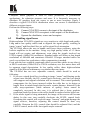
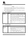
Kramer Electronics, Ltd.
USER MANUAL
1:2 VGA/XGA Distributor
Model:
VP-200xl
IMPORTANT: Before proceeding, please read paragraph entitled
"Unpacking and Contents"
KRAMER ELECTRONICS LTD.
Table Of Contents
Section
Name
1
INTRODUCTION
1.1
A Word on VGA/XGA/Audio Switchers
1.2
Handling Graphics Signals
1.3
Factors Affecting Quality of Results
2
HOW DO I GET STARTED
3
UNPACKING AND CONTENTS
3.1
Optional Accessories
4
VGA/XGA DISTRIBUTOR
4.1
Getting to know your VP-200xl Distributor
5
INSTALLATION
5.1
Rack Mounting
6
CONNECTING TO VGA/XGA DEVICES
6.1
TYPICAL APPLICATION
6.2
HANDLING SIGNAL LOSSES
6.3
Adding more outputs
6.4
Adding more inputs
7
SPECIFICATIONS
8
TROUBLESHOOTING
8.1
Power and Indicators
8.2
VGA/XGA Signal
Limited Warranty
Page
2
2
2
4
5
5
5
6
6
8
8
8
8
9
10
10
10
11
11
11
12
Figure
1
2
List Of Illustrations
Description
VP-200xl Front/Rear Panel Features
A typical application of the VP-200xl
Page
7
8
Table
1
List Of Tables
Description
VP-200xl Front/Rear Panel Features
Page
7
KRAMER ELECTRONICS LTD.
1
1
INTRODUCTION
Congratulations on your purchase of this Kramer VGA distributor. Since 1981,
Kramer has been dedicated to the development and manufacture of high quality
video/audio equipment. The Kramer line has become an integral part of many of
the best production and presentation facilities around the world. In recent years,
Kramer has redesigned and upgraded most of the line, making the best even
better. Kramer’s line of professional video/audio electronics is one of the most
versatile and complete available, and is a true leader in terms of quality,
workmanship, price/performance ratio and innovation. In addition to the Kramer
line of high quality VGA distributor, such as the one you have just purchased,
Kramer also offers a full line of high quality switchers, processors, interfaces,
controllers and computer-related products. This manual includes configuration,
operation and option information for the VP-200xl from the Kramer VP Tools
line, of VGA Distributors.
1.1
A Word on VGA/XGA Distribution Amplifiers
VGA/XGA Distribution Amplifiers distribute one or more signals to several
users. They vary in the number of inputs, looping capability, programming
capability, number of outputs, operating format, bandwidth and input/output
coupling. VGA/XGA Distribution Amplifiers are used to distribute one source to
several acceptors (wide screen projectors, format converters etc.) for
simultaneous recording or monitoring of one source, with no discernible signal
degradation. The machines excel in very large bandwidth (some approaching
400Mhz) and very good linearity, making them usable for even the highest
graphics standards. A good quality distribution amplifier amplifies the incoming
signal, may pre-compensate the signal for potential losses (resulting from the use
of long cables, noisy source, etc.) and generates several identical buffered and
amplified outputs. The front panels of these Kramer Amplifiers are designed to be
simple to operate. Typical applications of the machines are: computer graphics
distribution in classes, point of sale and multimedia studios, displaying computer
graphics before large audiences using the data input of a wide screen video
projector.
1.2
Handling Graphics Signals
A computer generated graphics signal usually comprises 5 signals: Red, Green,
Blue - which are analog level signals, and two TTL (logic) level signals Horizontal Sync and Vertical Sync. (Digital graphics cards and monitors use a
different signal format, and will not be discussed here.)
Computer graphics resolution is measured in pixels and signal bandwidth. The
more pixels (picture elements) on the screen, the more detailed the image. VGA,
S-VGA, XGA, S-XGA and U-XGA are terms describing graphics resolution and
KRAMER ELECTRONICS LTD.
2
color depth. Color depth represents the maximum number of simultaneously
displayed colors on the screen and is measured in bits. 24 and 32-36 bits of color
depth represent millions to billions of color shades available on the screen at any
given moment. (It should be born in mind, though, that the human eye can resolve
only a few thousands colors!) The more detailed the image (higher resolution)
and the higher the color depth the more real the image will look. The highest
resolution of standard VGA was 640x480 pixels with 4 bits of color (16 colors).
The standard VGA was able to use more colors (256) but at a lower resolution,
around 320x200 pixels, which was very crude. Common resolutions used
nowadays for computer graphics vary from 1024x768 up to 2000x1600 pixels
with “high color” - 16 bits of color, representing 64,000 different colors, up to
“true color” - 24 bits or more, representing from 16.7 million colors up to several
billion. Displaying such a detailed and colorful image on the screen needs
enormous graphics memory per frame, as well as very high speeds for “writing”
so many pixels on the screen in real time. The amplifiers that carry those signals
must be able to handle those speeds and signal bandwidth.
Standard VGA, at 640x480 resolution, needed amplifiers with 20-30MHz
bandwidth. At 1600x1200 or even at 1280x1024 (S-XGA), those amplifiers will
fail completely. In order to faithfully amplify and transmit modern highresolution graphics, amplifiers with bandwidths of 300 MHz and more are
needed. Those amplifiers, besides the enormous bandwidth they handle, need to
be linear, to have very low distortion and be stable. Stability of an amplifier is its
ability to avoid bursting into uncontrolled oscillation, which is in adverse
relationship to the speed it can handle. The tendency to oscillate is further
enhanced by the load impedance. The load impedance of a system is usually not
just a resistor. A cable connected to an amplifier (leading to the receiver or
monitor) may present a capacitive and/or an inductive load to the amplifier. This
is the main cause of instability. The quality problems of a load or cable may
severely degrade the bandwidth, linearity, and stability of the amplifier and in
general its ability to faithfully reproduce the signal.
Cables affect image resolution. Longer cables, due to imperfect characteristics,
cause high frequency deterioration and hence image “smear” and loss of
resolution. In computer graphics especially, this adverse effect is very much
accentuated. The amplifiers should therefore cope with an additional task compensating for cable losses up to the maximum useful operation distance.
High-resolution graphics systems should use very high quality cables for image
transmission. The cables should be shielded to eliminate externally induced
interference but the shield might itself increase the capacitance of the cable, and
therefore, cause deterioration in the image’s resolution and clarity. Standard
quality cables can only be a few meters long. For longer distances, compound
KRAMER ELECTRONICS LTD.
3
cable is replaced by five individual coax cables, which are bulky and
cumbersome for use. Even then, the distance is limited to several tens of meters.
Cables may create other problems, which result from their failure to accurately
match the system’s required impedance. The result of this, especially at high
frequencies, is “shadows” or “ghosts” on the image, resulting from standing
waves and electronic reflections running back and forth between transmitter and
receiver. Another aspect to consider is the sync. As sync signals are logic signals,
which are not treated as analog signals, the receiver does not terminate the line,
and therefore the line is not matched. A host of problems can occur when sync
signals are sent over long, unterminated, unmatched cables. The result might be
image breakdown or distortion due to improper sync information. The amplifier
that drives the analog section of the graphics data should also be able to buffer,
recover and send the sync information in such a way that it is received properly at
the receiving end.
1.3
Factors Affecting Quality of Results
There are many factors affecting the quality of results when signals are
transmitted from a source to an acceptor:
⌦
⌦
⌦
⌦
⌦
Connection cables - Low quality cables are susceptible to interference;
they degrade signal quality due to poor matching and cause elevated noise
levels. They should be of the best quality.
Sockets and connectors of the sources and acceptors - So often
ignored, they should be of highest quality, since "Zero Ohm" connection
resistance is the target. Sockets and connectors must also match the
required impedance (75ohm in video). Cheap, low quality connectors tend
to rust, thus causing breaks in the signal path.
Amplifying circuitry - Must provide quality performance when the
desired end result is high linearity, low distortion and low noise operation.
Distance between sources and acceptors - Plays a major role in the final
result. For long distances of over 15 meters (~2 to 3 meters for
VGA/XGA) between sources and acceptors, special measures should be
taken in order to avoid cable losses. These include using higher quality
cables or adding line amplifiers.
Interference from neighboring electrical appliances - They can have
an adverse effect on signal quality. Balanced audio lines are less prone to
interference, but unbalanced audio should be installed far from any mains
power cables, electric motors, transmitters, etc. even when the cables are
shielded.
KRAMER ELECTRONICS LTD.
4
2
HOW DO I GET STARTED?
The fastest way to get started is to take your time and do everything right the first
time. Taking 15 minutes to read the manual may save you a few hours later. You
don’t even have to read the whole manual. If a section doesn’t apply to you, you
don’t have to spend your time reading it.
3
UNPACKING AND CONTENTS
The items contained in your Kramer distributor package are listed below. Please
save the original box and packaging materials for possible future shipment.
!
3.1
Optional Accessories
The following accessories, which are available from Kramer, can enhance
implementation of your machine. For information regarding cables and additional
accessories, contact your Kramer dealer.
Rack Adapter - Used to install smaller size machines in a standard 1U or
3U rack space. One or more machines may be installed on each adapter.
VP-211 - (2x1 Automatic VGA/Audio Switcher) can be serially inserted
between the VGA/audio switcher and the acceptors for VGA/audio
distribution. It is a full bandwidth switcher designed for computer and
presentation applications. The VP-211 automatically detects the presence of
a VGA/XGA signal on input no. 1 and routes it to the output. If the signal
disappears, the machine switches to input no. 2 and routes it to the output.
When the signal on input no. 1 re-appears, the VP-211 reroutes input no. 1
to the output. The machine operates in audio-follow-video (VGA) mode and
switches the stereo audio input appropriate to the VGA input. Signal
bandwidth of 517MHz ensures that the VP-211 remains transparent even in
the most critical applications. The VP-211 is part of the Kramer TOOLS
family of compact, high quality and cost effective solutions for a variety of
applications.
KRAMER ELECTRONICS LTD.
5
VP-102 - (VGA to RGBS Converter) can be serially inserted between the
VGA distributor and the acceptors for VGA to RGBS conversion. It is a full
bandwidth machine especially designed for computer, workstation and
presentation applications. The VP-102 converts a VGA/Super-VGA/XGA
graphics card output to red, green, blue, horizontal/composite sync and
vertical sync signals available on BNC connectors. The VP-102 allows the
user to select either a composite or horizontal sync output and the green
output either includes composite sync or is blanked. The composite sync
generated by the machine is always at the correct polarity (negative), for
any polarity of Hs and Vs inputs. As the signal bandwidth is well over
315MHz, the VP-102 may be used with the highest quality graphics
workstations.
4
VGA/XGA DISTRIBUTOR
This section describes the controls and connections of your distributor.
Understanding the controls and connections helps you realize the full power of
your machine.
4.1
Getting to Know Your VP-200xl Distributor
The Kramer VP-200xl is a high performance 1:2 Line Amplifier / Distributor for
VGA/XGA signals. It accepts one input, provides correct buffering and isolation,
and then distributes the signal to two identical outputs using high-density 15 pin
“D” connectors. The machine has output level control, and cable equalization,
using two rotary controls on the front panel of the machine. Video bandwidth
exceeding 405 MHz ensures that the VP-200xl remains transparent even at the
highest resolution UXGA modes (1600x1200). It is ideal for dual monitor
applications, or presentation systems requiring a local monitor and a large screen
display such as a projector, at close or remote locations. A 12V power supply is
included. The VP-200xl is part of the Kramer TOOLS family of compact, high
quality, and cost effective solutions for a variety of applications.
KRAMER ELECTRONICS LTD.
6
Figure 1: VP-200xl Front/Rear Panel Features
Table 1: VP-200xl Front/Rear Panel Features
No. Feature
1
2
3
4
5
6
7
INPUT HD 15 connector
OUTPUT 1 HD 15 connector
OUTPUT 2 HD 15 connector
LEVEL Control Knob
EQ. Control Knob
ON LED
12VDC Socket
KRAMER ELECTRONICS LTD.
Function
VGA/XGA input
VGA/XGA output.
VGA/XGA output.
Adjusting VGA/XGA signal output level
Adjusting VGA/XGA cable equalization
Glows when power is supplied
12 Volts power feed to the machine
7
5 INSTALLATION
5.1
Rack Mounting
The VP-200xl distributor may be rackmounted in a standard 19” (1U or 3U) EIA
rack assembly, using either the RK-T1 optional adapter (1U rack space - for
mounting up to three machines) or the RK-T3 optional adapter (3U rack space
for mounting up to eight machines).
5.2
Connecting TO VGA/XGA Devices
VGA/XGA sources and output devices (such as monitors, projectors or recorders)
may be connected to the distributor through the HD 15F connectors located on
the back of the unit.
6 USING THE DISTRIBUTOR
6.1
Typical Application
A typical application is described in figure 2 below.
Figure 2: A typical application of the VP-200xl
KRAMER ELECTRONICS LTD.
8
Computer based graphics is used in video production, in presentation
applications, for education purposes and more. It is frequently necessary to
distribute PC graphics from one source to one or more acceptors. Figure 2
describes a typical VGA/XGA distribution where one source is distributed to
different acceptors inputs.
Perform the following steps:
1)
2)
3)
6.2
Connect VGA/XGA source to the input of the distributor.
Connect XGA/VGA acceptor/s to the output/s of the distributor.
Operate the distributor, source and acceptors.
Handling signal losses
High-resolution VGA/XGA signals are very sensitive to cable length and quality.
Long and/or low quality cables tend to degrade the signal quality, resulting in
image “smear” and fine-detail loss, as well as signal level attenuation.
The VP-200xl allows the user to handle and correct those problems, using the
built-in amplifiers in the machine. Using very high quality cables of 1-2 meter
length will not require and adjustment, even when the signals involved are
UXGA signals (1600x1200 resolution). Standard cables will allow at that length
resolutions of 640x480 and sometimes 800x600. If longer standard cables are
used, even at those low resolutions, cable compensation is needed.
Even with the best available compound cables (several thin cables in one sleeve)
at SXGA resolution (1280x1024) or UXGA resolution, over five meters there will
be apparent signal depreciation. In low quality cables, those high-resolution
signals will be affected at distances even shorter than one meter.
The VP-200xl has two user adjustable controls, which should be used as
following:
1. If you see a signal detail loss (resulting in image “smear” and blurring on the
screen) turn carefully the EQ. control knob clockwise, until the lost details
will reappear and original resolution will be resumed. This control gradually
compensates for the losses incurred within the cable due to its design or
length. Bear in mind though that beyond a certain distance, dictated by the
cable stray-capacitance (cable measure of quality) losses cannot be
completely recovered. In this case, it is advised that a lower graphics
resolution should be chosen or the cable should be replaced with a better one.
2. If the whole signal is being attenuated, the image on the screen will become
darker. In this case, turn carefully clockwise the LEVEL control knob.
Overdoing this control will result in image “burnout” and might damage the
signal receiver, therefore, adjusting this control should be done very
carefully. Between the EQ. control (that should be adjusted first) and the
LEVEL control, much of the lost signals maybe restored.
KRAMER ELECTRONICS LTD.
9
6.3
Adding more outputs
If more outputs than the two outputs the VP-200xl provides are needed, then any
of Kramer VGA/XGA distribution amplifiers may be used. The VP-200, for
example, provides 2 outputs, the VP-300 provides 3, the VP-400 provides 4 and
so on up to the VP-12 that is able to provide 12 parallel outputs from a single
input. All is needed is to connect one of the outputs of the VP-200xl to the input
of the selected distributor.
6.4
Adding more inputs
If more inputs are needed, then one of Kramer’s VGA/XGA switchers may be
installed in front of the VP-200xl. Some suitable machines are the VP-201 (2
inputs), VP-32xl (3 inputs), VP-61xl (6 inputs) etc.
7
SPECIFICATIONS
Analog Red, Green, Blue signals - 0.7 Vpp/75 Ω, H & V sync, TTL
level, on HD15F connector.
OUTPUTS: 2 Analog Red, Green, Blue signals - 0.7 Vpp/75 Ω, H & V syncsTTL level, on HD15F connectors.
VIDEO BANDWIDTH: Exceeding 405 MHz.
CONTROLS:
Level: -0.4 to +3.5dB, EQ.: 0 to +8dB @ 100 MHz
DIFF. GAIN:
<0.08%.
DIFF. PHASE:
<0.05 Deg.
COUPLING:
AC.
K-FACTOR:
<0.05%.
S/N RATIO:
73 dB.
POWER SOURCE:
12 VDC, 60 mA.
DIMENSIONS:
12cm x 7.5cm x 2.5cm (4.7"x2.95"x0.98", W, D, H.).
WEIGHT:
0.25 kg. (0.55 lbs.) Approx.
ACCESSORIES:
Power supply, mounting bracket.
OPTIONS:
Model VA-50P power supply with 6x12VDC outlets.
INPUT:
KRAMER ELECTRONICS LTD.
10
8
1.
2.
8.1
TROUBLESHOOTING
NOTES
Please note that if the output signal is disturbed or interrupted by very
strong external electromagnetic interference, it should return and stabilize
when such interference ends. If not, disconnect power from the machine and
reconnect again to reset the machine.
If the recommended actions still do not result in satisfactory operation,
please consult your KRAMER Dealer.
Power and Indicators
Problem
Remedy
No Power
1.
2.
3.
4.
8.2
Confirm that power connections are secured at the
machine and at the receptacle. Make sure the
receptacle is active, outputting the proper voltage.
If there is still no power use a Philips screwdriver, to
remove two screws on both sides of the machine and
release the panel (e.g. VP-200xl).
Locate the fuse holder located inside your machine.
Confirm that the fuse is good by looking for the wire
connected between the ends of the fuse. If this wire is
broken, replace the fuse with another, with the same
rating.
Install the machine's cover by tightening its Philips
screws.
VGA/XGA Signal
Problem
No VGA/XGA
the output
device
Remedy
1.
2.
3.
Confirm that your source and output devices are
powered on and connected properly. The input of your
machine should be of an identical signal format at the
output of your source.
Confirm that any other device in the signal path have
the proper input and/or output selected.
Use a VP-800 together with a known working
monitor to help trace faulty cables and equipment.
KRAMER ELECTRONICS LTD.
11
VGA/XGA
level is too high
or too dim.
Noise bars are
"rolling" up or
down in the
output image
or:
Low Frequency
Hum in the
output signal
1.
Verify that the lines are well matched through 75ohm
impedances; otherwise it results in a video level that is
too high or too dim.
2. Confirm that the connecting cables are of high quality
and properly inserted.
3. Check level controls on your source input device or
output display.
1. Hum bars (ground loop) are caused by a difference in
the ground potential of any two or more devices
connected to your signal path. This difference is
compensated by passing that voltage difference
through any available interconnection, including your
cables.
WARNING! Do not disconnect the ground from any
piece of equipment in your signal path!
2. Check the following to remove hum bars:
3. Confirm that all interconnected equipment is
connected to the same phase of power, if possible.
4. Remove equipment connected to that phase that may
introduce noise, such as motors, generators, etc.
5. Disconnect all interconnecting cables and reconnect
them one at a time until the ground loop reappears.
Disconnect the affected cable and replace, or insert an
isolation transformer in the signal path.
LIMITED WARRANTY
Kramer Electronics (hereafter Kramer) warrants this product free from defects in material
and workmanship under the following terms.
HOW LONG IS THE WARRANTY
Labor and parts are warranted for three years from the date of the first customer purchase.
WHO IS PROTECTED
Only the first purchase customer may enforce this warranty.
WHAT IS COVERED AND WHAT IS NOT COVERED
Except as below, this warranty covers all defects in material or workmanship in this
product. The following are not covered by the warranty:
1)
Any product which is not distributed by Kramer, or which is not purchased from
an authorized Kramer dealer. If you are uncertain as to whether a dealer is
KRAMER ELECTRONICS LTD.
12
authorized, please contact Kramer at one of the agents listed in the web site
www.kramerelectronics.com.
Any product, on which the serial number has been defaced, modified or removed.
Damage, deterioration or malfunction resulting from:
a)
Accident, misuse, abuse, neglect, fire, water, lightning or other acts of
nature.
b)
Product modification, or failure to follow instructions supplied with the
product.
c)
Repair or attempted repair by anyone not authorized by Kramer.
d)
Any shipment of the product (claims must be presented to the carrier).
e)
Removal or installation of the product.
f)
Any other cause, which does not relate to a product defect.
g)
Cartons, equipment enclosures, cables or accessories used in
conjunction with the product.
2)
3)
WHAT WE WILL PAY FOR AND WHAT WE WILL NOT PAY FOR
We will pay labor and material expenses for covered items. We will not pay for the
following:
1) Removal or installations charges.
2) Costs of initial technical adjustments (set-up), including adjustment of user controls
or programming. These costs are the responsibility of the Kramer dealer from
whom the product was purchased.
3) Shipping charges.
HOW YOU CAN GET WARRANTY SERVICE
1) To obtain service on you product, you must take or ship it prepaid to any
authorized Kramer service center.
2) Whenever warranty service is required, the original dated invoice (or a copy) must
be presented as proof of warranty coverage, and should be included in any
shipment of the product. Please also include in any mailing a contact name,
company, address, and a description of the problem(s).
3) For the name of the nearest Kramer authorized service center, consult your
authorized dealer.
LIMITATION OF IMPLIED WARRANTIES
All implied warranties, including warranties of merchantability and fitness for a particular
purpose, are limited in duration to the length of this warranty.
EXCLUSION OF DAMAGES
Kramer’s liability for any defective products is limited to the repair or replacement of the
product at our option. Kramer shall not be liable for:
1)
2)
Damage to other property caused by defects in this product, damages based upon
inconvenience, loss of use of the product, loss of time, commercial loss; or:
Any other damages, whether incidental, consequential or otherwise. Some
countries may not allow limitations on how long an implied warranty lasts and/or
KRAMER ELECTRONICS LTD.
13
do not allow the exclusion or limitation of incidental or consequential damages, so
the above limitations and exclusions may not apply to you.
This warranty gives you specific legal rights, and you may also have other rights, which
vary from place to place.
NOTE: All products returned to Kramer for service must have prior approval. This may be
obtained from your dealer.
NOTICE
This equipment has been tested to determine compliance with the requirements of:
EN-50081:
"Electromagnetic compatibility (EMC);
generic emission standard.
Part 1: Residential, commercial and light industry"
EN-50082:
"Electromagnetic compatibility (EMC) generic immunity standard.
Part 1: Residential, commercial and light industry environment".
FCC Rules and Regulations:
CFR-47
Part 15- “Radio frequency devices:
Subpart B- Unintentional radiators”
CAUTION!
Servicing the machines can only be done by an authorized Kramer
technician. Any user who makes changes or modifications to the unit without
the expressed approval of the manufacturer will void user authority to operate
the equipment.
⌦
Use the supplied DC power supply to feed power to the machine.
⌦
Please use recommended interconnection cables to connect the machine to
other components.
⌦
KRAMER ELECTRONICS LTD.
14
For the latest information on our products and a list of Kramer
distributors, visit our Web site: www.kramerelectronics.com,
where updates to this user manual may be found.
We welcome your questions, comments and feedback.
Safety Warning:
Disconnect the unit from the power supply before
opening/servicing.
Caution
Kramer Electronics, Ltd.
Web site: www.kramerelectronics.com
E-mail: [email protected]
P/N: 2900-001039 REV 2