1
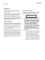
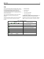
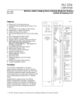
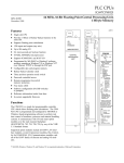
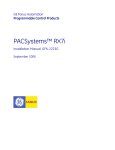
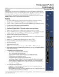
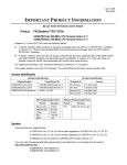
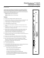
PACSystems™ RX7i
IC698CPE010/CPE020
GFK-2226B
December 2003
Central Processing Unit
The RX7i CPUs are programmed and configured by the programming software to
perform real time control of machines, processes, and material handling systems.
The CPU communicates with I/O and smart option modules over a rack-mounted
backplane using the VME64 Standard format. It communicates with the programmer
and HMI devices via the embedded Ethernet ports.
CPU
700MHz
CPE010: 300MHz Celeron microprocessor
CPE020: 700MHz Pentium III microprocessor
OK
RUN
ENA
Features
■
Provides access to bulk memory via reference table %W. The upper limit of this
memory area can be configured to the maximum available user RAM.
■
Contains 10Mbyte of non-volatile flash user memory.
■
Configurable data and program memory.
■
Supports auto-located Symbolic Variables that can use any amount of user
memory.
■
Larger reference table sizes include 32Kbits for discrete %I and %Q and up to
32Kwords each for analog %AI and %AQ.
■
Supports Series 90-70 discrete and analog I/O, Genius Bus Controller, High
Speed Counter, Communications Coprocessor Module, Programmable
Coprocessor Module, and DLAN/DLAN+ Interface Modules.
■
Supports all non-GE Fanuc VME module supported by Series 90-70.
■
Supports PLC data monitoring over the web. Allows a combined total of up to 16
web server and FTP connections.
■
Supports up to 512 program blocks. Maximum size for a block is 128KB.
■
Test Edit mode allows you to easily test modifications to a running program.
■
Bit-in-word referencing allows you to specify individual bits in a WORD
reference in retentive memory as inputs and outputs of Boolean expressions,
function blocks, and calls that accept bit parameters.
■
Battery-backed calendar clock.
■
In-system upgradeable firmware.
■
Three serial ports: an RS-485 isolated serial port, an RS-232 isolated serial port,
and an RS-232 isolated Ethernet station manager serial port.
■
The embedded Ethernet interface provides:
−
Data exchange using Ethernet Global Data (EGD)
−
TCP/IP communication services using SRTP
−
Full PLC programming and configuration services
−
Comprehensive station management and diagnostic tools
−
Two full-duplex 10BaseT/100BaseT/TX (RJ-45 Connector) ports with an
internal network switch providing auto-negotiated network speed, duplex
mode, and crossover detection.
BATTERY
ACCESS
RUN
ENABLE
RUN
DIS
STOP
RESET
BATTERY
ACCESS
C
O
M
2
C1
C2
ACTIVE
S
T
A
C
O
M
1
M
G
R
EOK
LAN
STAT
10/100 ETHERNET P1
Supports up to 10 Mbytes of battery-backed user memory.
10/100 ETHERNET P2
■
100 LINK
100 LINK
ETHERNET
RESTART
PMC
RX7i CPU
2
GFK-2226B
Programmer
PACSystems
(Rack 0)
P
S
C
P
U
G
B
C
B
T
M
or
N
B
C
Genius I/O Bus (7500 feet/2285 meters maximum)
one
meter
Series 90-70
(Rack 1)
P
S
B
R
M
Genius
I/O Blocks
Note
Series 90-70
(Rack 6)
P
S
G
B
C
or
N
B
C
B
R
M
Total length of all interconnecting
cables from BTM to last BRM is 50 feet
(15 meters) maximum. All racks must
be at same ground potential
(8 racks maximum).
Genius I/O bus (7500 feet/2285 meters maximum)
one
meter
Series 90-70
(Rack 7)
P
S
B
R
M
I/O Terminator
(last rack)
Legend
CPU BRM BTM GBC -
CPU
BUS RECEIVER MODULE, BEM711
BUS TRANSMITTER MODULE, BEM713
BUS CONTROLLER, BEM731/734
PS -
Power Supply
Figure 1. Control System Configuration Example
User RAM Memory
The CPE010 and CPE020 have 10 Mbytes of batterybacked CMOS RAM memory for user data (program,
configuration, register data, and symbolic variable) storage.
User Flash Memory
The CPE010 and CPU020 have 10Mbytes of built-in flash
memory for user data (program, configuration, register data,
and symbolic variable) storage. Use of this flash memory is
optional.
Operation, Protection, and Module Status
Operation of this module can be controlled by the threeposition RUN/STOP switch or remotely by an attached
programmer and programming software. Program and
configuration data can be locked through software
passwords. The status of the CPU is indicated by the three
CPU LEDs on the front of the module. (For details, see
“Indicators”). Two LEDs indicate activity on the serial ports.
Seven additional LEDs indicate the status of the Ethernet
interface.
Battery
A three-cell lithium battery pack (IC698ACC701) is installed
as shown in Figure 2. The battery maintains program and
data memory when power is removed and operates the
calendar clock. When replacing the battery, be sure to install
a new battery before disconnecting the old one.
Disposal of lithium batteries must be done in
accordance with federal, state, and local regulations. Be
sure to consult with the appropriate regulatory agencies
before disposing of batteries. For details, refer to the
Material Safety Data Sheet provided with the battery.
Specific indication of a low or failed battery is described in
the PACSystems RX7i User’s Manual, GFK-2222.
Battery
Compartment
Three-cell
Battery Pack
MAC Label
located on rear wall of
battery compartment
Firmware Storage in Flash Memory
This CPU uses non-volatile flash memory for storing the
operating system firmware. This allows firmware to be
updated without disassembling the module or replacing
EPROMs. The operating system firmware is updated by
connecting a PC compatible computer to the module’s RS232 serial port and running the software included with the
firmware upgrade kit.
Figure 2. Battery Compartment
RX7i CPU
3
GFK-2226B
Installation
Programmer Connection, Ethernet TCP/IP
It is the responsibility of the OEM, system integrator, or end
user to properly install the control system equipment for safe
and reliable operation. Product manuals provide detailed
information about installation, startup, and proper use of the
control system equipment.
For programmer operation, connect the programmer
computer to one of the RJ-45 Ethernet ports. For a
description of programming functions, consult CIMPLICITY®
Machine Edition Logic Developer-PLC Getting Started, GFK1918 and the programming software online help.
Installation should not be attempted without referring to the
PACSystems RX7i Installation Manual, GFK-2223.
Connecting your programmer via an Ethernet TCP/IP
network requires a CAT5 standard Ethernet cable with RJ-45
connectors. Before connecting the programmer and RX7i to
the Ethernet TCP/IP network you must set the IP address in
the CPE010/020, using the Initial IP Address software tool.
After setting the IP address, connect the RX7i and the
computer running the programming software to the Ethernet
Interface. For detailed information on the programmer
connection via Ethernet TCP/IP, refer to the TCP/IP Ethernet
Communications for the PACSystems RX7i User’s Manual,
GFK-2224.
1.
Read and record the 12-digit hexadecimal MAC
Address from the printed label located inside the battery
compartment.
2.
Make sure that rack power is off.
3.
Install the CPU module in slot 1 of rack 0 (see Figure 1).
Ensure mounting screws are tightened to completely
secure the CPU in the rack.
4.
Connect one or both Ethernet ports to the Ethernet
network.
5.
Turn on power.
6.
Connect the battery to either of the battery connectors
on the module. (You can connect the battery at any step
in the installation process but it will begin to drain
immediately unless power is applied. To maximize
battery life, install it after power has been turned on).
The module should power up. When the CPU has
successfully completed initialization, the OK LED stays on
and the RUN and EN LEDs are off; the EOK LED stays on.
The CPU is now ready to be programmed.
After the program has been verified, the toggle switch can be
moved to the appropriate operation mode position: RUN EN
(run with outputs enabled), RUN DIS (run with outputs
disabled), or STOP. The LEDs indicate the position of the
toggle switch, status of serial port activity, status of Ethernet
interface including Ethernet OK, LAN, STATus, activity, and
10 or 100Mbps rate used. For details, see “LEDs” on page 6.
Serial Ports
The CPU has three independent, on-board serial ports,
accessed by connectors on the front of the module. Two of
these ports provide serial interfaces to external devices.
Port 1 is also used for firmware upgrades. The third onboard serial port is used as the Ethernet station manager
port. All serial ports are isolated.
Table 1. Protocols Supported
Protocol
RTU (slave)
Firmware Upgrade
Port 1
Port 2
Station Mgr
Yes
Yes
No
RX7i in STOP/ No
I/O mode
No
No
Table 2. Serial Port Baud Rates and Functions
Protocol
Port 1
(RS-232)
Port 2
(RS-485)
Station Mgr
(RS-232)
Modbus RTU
Slave
protocol
1200, 2400, 4800, 9600,
19.2K, 38.4K, 57.6K, 115.2K
not supported
Message
1200, 2400, 4800, 9600,
19.2K, 38.4K, 57.6K, 115.2K
1200, 2400,
4800, 9600,
19.2K, 38.4K,
57.6K, 115.2K
(Default: 9600)
Firmware
Upgrade via
Winloader
1200, 2400,
4800, 9600,
19.2K,
38.4K, 57.6K
not supported
not
supported
4
RX7i CPU
GFK-2226B
Serial Cable Lengths and Shielding
Port 2
The connection from a CPU serial port COM1 to the serial
port on a computer or other serial device requires a serial
cable. This connection can be made with the IC200CBL001
cable kit or you can build cables to fit the needs of your
particular application. See the PACSystems RX7i User’s
Manual, GFK-2222 for more information on serial
communications, cables, and converters.
Port 2, the top serial port, is RS-485 compatible and is
optocoupler isolated. Port 2 has a 15-pin, female D-sub
connector. This port does not support the RS-485 to RS-232
adapter (IC690ACC901). This is a DCE port.
The Port 2 indicator provides the status of serial port activity
without having a terminal connected.
Table 4. Port 2 RS-485 Signals
Maximum cable lengths (the total number of feet from the
CPU to the last device attached to the serial cable) are:
■ Port 1 (RS-232) – 15 meters (50 ft.), shielded cable
Pin
No.
Signal
Name
Description
1*
Shield
Cable Shield
2
NC
No Connection
3
NC
No Connection
4
NC
No Connection
5
NC
No Connection
6
RTS(A)
Differential Request to Send
7
0V
Signal Ground
Port 1, the lower left port, is RS-232 compatible and is
optocoupler isolated. It has a 9-pin, female, D-sub connector
with a standard pin out. This is a DCE (data communications
equipment) port that allows a simple straight-through cable
to connect with a standard AT-style RS-232 port.
8
CTS(B‘)
Differential Clear To Send
9**
RT
Resistor Termination
The Port 1 indicator provides the status of serial port activity.
optional
■ Port 2 (RS-485) – 1200 meters (4000 ft.), shielded cable
required
■ Station Manager (RS-232) – 15 meters (50 ft.), shielded
cable optional
Port 1
Table 3. Port 1 RS-232 Signals
Pin
Number
*
Signal
Name
Description
1*
NC
No Connection
2
TXD
Transmit Data
3
RXD
Receive Data
4
DSR
Data Set Ready
5
0V
Signal Ground
6
DTR
Data Terminal Ready
7
CTS
Clear To Send
8
RTS
Request to Send
9
NC
No Connection
Pin 1 is at the bottom right of the connector as viewed
from the front of the module.
10**
RD(A‘)
Differential Receive Data
11
RD(B‘)
Differential Receive Data
12
SD(A)
Differential Send Data
13
SD(B)
Differential Send Data
14
RTS(B)
Differential Request To Send
CTS(A’)
Differential Clear To Send
15
*
Pin 1 is at the bottom right of the connector as
viewed from the front of the module.
**
Termination resistance for the RD A’ signal should
be connected on units at the end of the line. To
make this termination, connect a jumper between
pins 9 and 10 inside the 15-pin D-shell.
RX7i CPU
5
GFK-2226B
Station Manager Port
RJ-45 Ethernet Network Ports
The station manager port, labeled STA MGR, is RS-232
compatible, DCE, and isolated. It has a 9-pin, female, Dconnector that accepts a standard straight-through cable
(such as IC200CBL001) to connect with a standard AT-style
RS-232 port. This port contains full use of the standard
RS-232 signals for future use with point-to-point protocol.
Table 5. Station Manager RS-232 Signals
Pin
Number
Signal
Name
1*
DCD
2
TXD
Transmit Data
3
RXD
Receive Data
4
DSR
Data Set Ready
5
0V
Signal Ground
6
DTR
Data Terminal Ready
7
CTS
Clear To Send
8
RTS
Request to Send
9
RI
Description
Data Carrier Detect
Ring Indicator
* Pin 1 is at the bottom right of the connector as viewed
from the front of the module.
Station Manager Operation
Operating a local area network entails certain LAN
management activities such as network performance
measurement, status information, and fault diagnosis.
The Ethernet Interface contains many features to support
these activities. Some of these features are accessed via the
Station Manager, a portion of the Ethernet Interface
operating firmware that responds to user commands. The
Station Manager operates locally via an ASCII terminal or
terminal emulator connected to the dedicated Station Mgr
(RS-232) serial port, or remotely over the Ethernet LAN.
Refer to the PACSystems RX7i TCP/IP Ethernet
Communications Station Manager Manual, GFK-2225 for
complete information on the Station Manager.
Each RX7i Ethernet interface provides a dedicated RS-232
serial port for local Station Manager use. The Ethernet
Interface does not use this port for firmware upgrades. See
“Firmware Upgrades” on page 9 for firmware upgrade
details.
Caution
The two ports on the Ethernet interface must
not be connected, directly or indirectly, to the
same device. The hub or switch connections in
an Ethernet network must form a tree and not a
ring; otherwise duplication of packets and
network overload may result.
Note:
The CPU module has two RJ-45 connectors but
only one IP address.
Each RX7i Ethernet interface contains two eight-conductor
RJ-45 shielded twisted pair Ethernet ports, labeled Port 1
and Port 2, for connection to either a 10BaseT or
100BaseTX IEEE 802.3 network. Either shielded or
unshielded twisted pair cable can be attached to a port.
Each Ethernet port automatically senses whether it is
connected to a 10BaseT or 100BaseTX network, half-duplex
or full-duplex. The user does not configure the network type.
(The automatic negotiation of speed and/or duplex mode can
be overridden by using AUP settings.) Standard twisted pair
Ethernet cable is used for connection to other devices.
Category 5 cable is required for 100BaseTX operation.
Each network port automatically operates in normal or
crossover mode. This capability allows directly wiring the
Ethernet interface to another device without an intervening
network hub/switch, and without a special crossover cable.
This allows you to connect RX7i Ethernet interfaces in a
daisy chain arrangement. Care should be taken when using
daisy chaining, since power loss or reset at an Ethernet
interface will cause loss of communication to devices
downstream from that Ethernet interface in the daisy chain.
Restarting the Ethernet interface (using the Ethernet Restart
pushbutton, for example) also disrupts daisy chain
communication.
Table 6. Ethernet Port Signals
Ethernet
10BaseT
100BaseTX
Pin No.
1
Transmit +
2
Transmit -
3
Receive +
4
N/A
5
N/A
6
Receive -
7
N/A
8
N/A
Pin Position on RJ-45
Connector
* Pin 1 is at the bottom of the connector as viewed from the
front of the module.
6
RX7i CPU
GFK-2226B
Configuration
The RX7i CPU and I/O system is configured with
CIMPLICITY® Machine Edition PLC-Logic Developer
programming software.
The CPU verifies the actual module and rack configuration at
power-up and periodically during operation. The actual
configuration must be the same as the programmed
configuration. Deviations are reported to the CPU alarm
processor function for configured fault response. Refer to the
CIMPLICITY® Machine Edition Logic Developer-PLC
Getting Started Manual, GFK-1918 and the online help for a
description of configuration functions.
Ethernet Configuration
Essential network addresses for an Ethernet Interface are
set up using the CIMPLICITY Machine Edition configuration
software and stored to the CPU. These addresses must be
properly configured before the Ethernet Interface can be
used by your application. The configuration process is
described in the TCP/IP Ethernet Communications for the
RX7i User’s Manual, GFK-2224.
Note that CIMPLICITY Machine Edition software connects to
the RX7i via Ethernet. For initial installation when there is no
IP addressing information in the RX7i Ethernet Interface,
CIMPLICITY Machine Edition (or Local Station Manager) is
used to initially assign an IP address to the Ethernet
Interface. Once set up, the Ethernet Interface retains the IP
addressing information. The IP addressing information can
be changed by storing a new configuration to the CPU.
Advanced User Parameters
Advanced User Parameters (AUP) are internal operating
parameters used by the Ethernet interface. For most
applications, the default AUP should not be changed.
Caution
The IEEE 802.3 standard strongly discourages
the manual configuration of duplex mode for a
port (as would be possible using Advanced
User Parameters). Before manually configuring
duplex mode for a port using AUP, be sure that
you know the characteristics of the link partner
and are aware of the consequences of your
selection. In the words of the IEEE standard:
“Connecting incompatible DTE/MAU
combinations such as full duplex mode DTE to
a half duplex mode MAU, or a full-duplex station
(DTE or MAU) to a repeater or other half duplex
network, can lead to severe network
performance degradation, increased collisions,
late collisions, CRC errors, and undetected data
corruption.”
Note:
If both speed and duplex mode of an Ethernet
interface port are forced using AUP, that port will no
longer perform automatic cable detection. This
means that if the Ethernet interface port is
connected to an external switch or hub port, a
crossover cable must be used. If the Ethernet
interface port is connected to the uplink port on an
external switch or hub, or the Ethernet interface
port is directly connected to another Ethernet
device, a normal (straight-through) cable must be
used.
RX7i CPU
7
GFK-2226B
LEDs
The three CPU LEDs indicate the operating status of various
CPU functions. During powerup, the LEDs are turned on and
off in the initialization sequence. When the CPU has
successfully completed initialization, the OK LED stays on.
The RUN and EN LEDs are off or on, depending on the CPU
state at last power-down.
The two port LEDs indicate activity on COM 1 and COM 2.
Table 7 lists the CPU LED functions during normal
operation.
The Ethernet Interface indicators consist of seven LEDs. All
are single-color green LEDs controlled by the Ethernet
interface.
•
Module OK (EOK)
•
LAN online (LAN)
•
Status (STAT)
•
Two activity LEDS (LINK)
•
Two speed LEDS (100)
The EOK, LAN, and STAT LEDs are grouped together and
indicate the state and status of the Ethernet interface.
Each Ethernet port has two green LED indicators, 100 and
LINK. The Ethernet LED operation is described in Table 8.
Table 7. CPU LED Operation*
LED State
On
Blinking
OK
Off
CPU Operating State
On
CPU has passed its powerup diagnostics
and is functioning properly.
OK
Off
CPU problem.
OK, EN, RUN
Blinking in unison
CPU is in boot mode and is waiting for a
firmware update through serial port.
RUN
On
CPU is in Run mode
RUN
Off
CPU is in Stop mode.
EN
On
Output scan is enabled.
EN
Off
Output scan is disabled.
Port 1
Port 2
Blinking
Blinking
Signal activity on port.
*After initialization sequence is complete.
8
RX7i CPU
GFK-2226B
Table 8. Ethernet LED Operation
LED State
On
Blinking
Off
Ethernet Operating State
EOK
LAN
STAT
Blink error code
Off
Off
Hardware Failure
EOK
LAN
STAT
Fast Blink
Off
Off
Performing Diagnostics
EOK
LAN
STAT
Slow Blink
Off
Off
Waiting for Ethernet configuration from CPU
EOK
Slow Blink*
LAN
On/Traffic/Off
STAT
Slow Blink*
(* EOK and STAT blink in unison)
Waiting for IP Address
EOK
LAN
STAT
Operational
On
On/Traffic/Off
On/Off
EOK
Slow Blink*
LAN
Slow Blink*
STAT
Slow Blink*
(* All LEDs blink in unison)
Software Load
EOK LED Operation
STAT LED Operation
The EOK LED indicates whether the Ethernet interface is
able to perform normal operation. This LED is on for
normal operation and flashing for all other operations.
When a hardware or unrecoverable runtime failure occurs,
the EOK LED blinks a two-digit error code identifying the
failure. The LED first blinks to indicate the most significant
error digit, then after a brief pause blinks again to indicate
the least significant error digit. After a long pause the error
code display repeats. For definitions of LED blink codes,
refer to the TCP/IP Ethernet Communications for the RX7i
User’s Manual, GFK-2224.
The STAT LED indicates the condition of the Ethernet
interface in normal operational mode. If the STAT LED is
off, an event has been entered into the exception log and
is available for viewing via the Station Manager interface.
The STAT LED is on during normal operation when no
events are logged.
LAN LED Operation
The LAN LED indicates access to the Ethernet network.
During normal operation and while waiting for an IP
address, the LAN LED blinks to indicate network activity.
This LED remains on when the Ethernet interface is not
actively accessing the network but the network is
available, and it is off if network access is not available.
The definition of the network being available as indicated
by this LED is that the Ethernet physical interface is
available and one or both of the Ethernet ports is
connected to an active network.
In the other states, the STAT LED is either off or blinking
and helps define the operational state of the module.
Ethernet Port LEDs Operation (100Mb and
Link/Activity)
Each of the two Ethernet ports has two green LED
indicators, 100 and LINK. The 100 LED indicates the
network data speed (10 or 100 Mb/sec). This LED is
illuminated if the network connection is 100 Mbps.
The LINK LED indicates the network link status and
activity. This LED is illuminated when the link is physically
connected and blinks when traffic is detected at the port.
Note that traffic at the port does not necessarily mean that
traffic is present at the RX7i Ethernet interface, since the
traffic may be going between ports of the switch.
RX7i CPU
9
GFK-2226B
Ethernet Restart Pushbutton
This pushbutton is used to manually restart the Ethernet
firmware without power cycling the entire control system. It
is recessed to prevent accidental operation.
LED Operation during Restart
When the Ethernet firmware is manually restarted by the
Ethernet pushbutton in any state, the EOK, LAN and
STAT LEDs are briefly turned on in unison as an LED test.
These three LEDs are turned on for ½ second and are
then turned off when the firmware is restarted. The
Ethernet port LEDs are not affected by a manual restart of
the Ethernet firmware.
The LED test is performed only upon a manual pushbutton
restart; there is no LED test when the Station Manager
initiates a restart.
Ethernet Global Data (EGD)
Each RX7i CPU supports up to 255 simultaneous Ethernet
Global Data (EGD) exchanges across all Ethernet
interfaces in the PLC. EGD exchanges must be configured
in the programming software and stored into the CPU. The
EGD configuration can also be loaded from the CPU into
the programming software. Both produced and consumed
exchanges can be configured. RX7i CPUs support using
only part of a consumed EGD exchange, and EGD
exchange production and consumption to the broadcast IP
address of the local subnet.
User Web Pages (Web Server)
Each RX7i CPU Ethernet interface supports World Wide
Web access via HTTP to allow web pages to be stored
and maintained on the Ethernet interface and served up
via the web to standard web browsers.
The CPU Ethernet interface contains a basic set of
predefined PLC web pages that display Reference Table
data, PLC Fault Table contents, and IO Fault Table
contents. In the future, new or revised web pages can be
stored into the CPU Ethernet interface via FTP.
Firmware Upgrades
The CPU and its Ethernet interface receive their firmware
upgrades through a CPU serial port. The user connects
WinLoader to the CPU RS-232 serial port and specifies
the CPU module by its Rack/Slot location. During firmware
upgrade the CPU and Ethernet modules are presented as
a single entity. WinLoader seamlessly upgrades first the
CPU firmware and then the Ethernet firmware without user
intervention.
Removing a CPU from the Rack
The instructions listed below should be followed when
removing a CPU from its slot in a rack.
1.
Turn off power to the rack.
2.
Disconnect any serial and Ethernet cables.
The RX7i CPU supports 2msec EGD exchange production
and timeout resolution. RX7i EGD exchanges can be
configured for a production period of 0, indicating the
exchange is to be produced every output scan. These “as
fast as possible” exchanges are not produced more often
than 2msec. RX7i CPUs support enhanced EGD
freshness, providing better EGD timeliness than Series
90-70 CPU products.
3.
Unscrew the top and bottom mounting screws to
release the board from the chassis. The screws
should stay mounted in the faceplate but allow the
faceplate to be separated from the chassis rails.
4.
Grasp the board firmly at the top and bottom of the
faceplate with your thumbs on the front of the cover
and your fingers on the back of the cover.
During EGD configuration, RX7i Ethernet interfaces are
identified by their Rack/Slot location.
5.
Pull the board firmly to remove it from the backplane
connector.
6.
Slide the board along the card guide and remove it
from the rack.
10
RX7i CPU
GFK-2226A
Specifications for IC698CPE010 and CPE020*
Battery Memory retention
5 years at 20°C (68°F)
40 days nominal without applied power.
Program storage
Up to 10 Mbytes of battery-backed RAM
10 Mbytes of non-volatile flash user memory
Current required from 5V bus
CPE010: 3.6 Amps nominal
CPE020: 4.0 Amps nominal
Operating Temperature
CPE010: 0 to 50°C (32°F to 122°F)
0 to 60°C (32°F to 140°F) with fan tray
CPE020: 0 to 60°C (32°F to 140°F) with fan tray, required
Floating point
Yes
Boolean execution speed, typical
CPE010
CPE020
0.33ms per 1000 Boolean contacts/coils
0.14ms per 1000 Boolean contacts/coils
Time of Day Clock accuracy
Maximum of 9 seconds per day
Elapsed Time Clock (internal timing) accuracy
0.01% maximum
Embedded communications
RS-232, RS-485, Ethernet interface
Ethernet Ports
Embedded auto-sensing 10/100 Mbps half/full duplex Ethernet
interface
Serial Ports
Port 1: RS-232 compatible(optocoupler isolated)
Port 2: RS-485 compatible (optocoupler isolated)
Station Mgr: RS-232 compatible (optocoupler isolated)
Protocols supported: Modbus RTU Slave
RTU Slave
RTU Slave
RTU Slave not supported
VME Compatibility
System designed to support the VME64 standard ANSI/VITA 1
Program blocks
Up to 512 program blocks. Maximum size for a block is 128KB.
Memory
%I and %Q: 32Kbits for discrete
%AI and %AQ: configurable up to 32Kwords
%W: configurable up the maximum available user RAM
Symbolic: configurable up to 10Mbytes
*
For environmental specifications and compliance to standards (for example, FCC or European Union Directives), refer to
Appendix A of the PACSystems RX7i Installation Manual, GFK-2223.
Ordering Information
Description
Catalog Number
RX7i VME 300Mhz CPU
IC698CPE010
RX7i VME 700Mhz CPU
IC698CPE020
Lithium Battery pack
IC698ACC701
Rack Fan Assembly, 120VAC
Rack Fan Assembly, 240VAC
Rack Fan Assembly, 24VDC
IC697ACC721
IC697ACC724
IC697ACC744
RX7i PLC Power Supply, 85 to 264 VAC at 47 to 63 Hz Input, 100 watt output
IC698PSA100
RX7i PLC Power Supply, 85 to 264 VAC at 47 to 63 Hz Input, 350 watt output
IC698PSA350
[Optional] RS-232 cable; also Station Manager cable for Ethernet interface
IC200CBL001
Note: For Conformal Coat option, please consult the factory for price and availability.