1
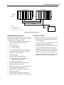
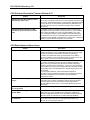
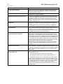
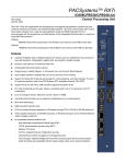
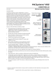
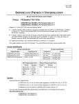
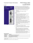
PACSystems* RX7i IC698CRE020-KW GFK-2320AA June 2012 Redundancy CPU The RX7i CPUs are programmed and configured by the programming software to perform real time control of machines, processes, and material handling systems. The CPU communicates with I/O and smart option modules over a rack-mounted backplane using the VME64 Standard format. It communicates with the programmer and HMI devices via the embedded Ethernet port or serial port. CRE020: 700MHz Pentium III microprocessor with redundancy Features ▪ Hot standby (HSB) redundancy. Requires a Redundancy CPU and a Redundancy Memory Xchange module (IC698RMX016) configured as a redundancy link in each unit. ▪ Contains 10 Mbytes of battery-backed user memory and 10 Mbytes of non-volatile flash memory. ▪ Provides access to bulk memory via reference table %W. ▪ ▪ Configurable data and program memory. ▪ Supports auto-located Symbolic Variables that can use any amount of user memory. ▪ Supports Series 90-70 discrete and analog I/O, communications, and other modules. For a list of modules supported, refer to the PACSystems RX7i Installation Manual, GFK-2223. ▪ Supports all VME modules supported by Series 90-70. ▪ Supports data monitoring over the web. Allows a combined total of up to 16 web server and FTP connections. ▪ Supports up to 512 program blocks. Maximum size for a block is 128KB. ▪ Test Edit mode allows you to easily test modifications to a running program. ▪ Bit-in-word referencing. ▪ Battery-backed calendar clock. ▪ CPU and module firmware upgrades through the CPU’s RS-232 or RS-485 serial port. ▪ Three isolated serial ports: an RS-485 serial port, an RS-232 serial port, and an RS-232 Ethernet station manager serial port. ▪ An embedded Ethernet interface provides: ▪ Programming in Ladder Diagram, C, Structured Text and Function Block Diagram. Data exchange using Ethernet Global Data (EGD) TCP/IP communication services using SRTP Support for SRTP Channels, Modbus/TCP Server and Modbus/TCP Client Full programming and configuration services Comprehensive station management and diagnostic tools Two full-duplex 10BaseT/100BaseT/TX (RJ-45 Connector) ports with an internal network switch providing auto-negotiated network speed, duplex mode, and crossover detection. Time synchronization to SNTP timeserver on Ethernet network (when used with Release 5.00 or later CPU module). User-configurable Redundant IP allows: Configuration of EGD exchanges to be produced from the active and inactive Ethernet interface(s) in an HSB Redundant pair. Within a HSB Redundant CPU, production of EGD exchanges from an Ethernet interface that does not have a Redundant IP address configured. * indicates a trademark of GE Intelligent Platforms, Inc. and/or its affiliates. All other trademarks are the property of their respective owners. All rights reserved. RX7i CRE020 Redundancy CPU 2 GFK-2320AA GBC RMX CPU RMX Power Supply Primary Unit GBC RMX CPU RMX RX7i (Rack 0) Power Supply Secondary Unit Required fan assembly not shown. 30 31 High-speed fiber optic link* High-speed fiber optic link* Genius Bus Remote Drop Legend CPU RMX GBC - RX7i Redundancy CPU Redundancy Memory Xchange Module Genius Bus Controller *Supports up to 30.48m/100ft fiber optic cable. CPU Redundancy System Configuration HSB CPU Redundancy Features HSB Control Strategy For details on the configuration and operation of an RX7i CPU redundancy system, refer to the PACSystems CPU Redundancy User’s Manual, GFK-2308. The HSB control strategy has the following characteristics: ▪ Survives any one single point of failure (excluding failures of Genius devices and bus stubs) ▪ Bumpless switching ▪ ▪ ▪ ▪ Synchronized CPUs One scan switching Configurable transfer data size up to 2Mbytes Supports two redundancy communications links Online repair of failed component Online programming Redundancy Memory Xchange Module Manual toggle switch for switching control between active and backup units Redundancy status LEDs ▪ ▪ ▪ Redundancy status bits and message logging ▪ ▪ ▪ ▪ Supports single and dual Genius bus networks Application-initiated role switching Memory Error Checking and Correction (ECC single bit correcting and multiple bit checking) Background diagnostics Run-mode Store of Redundancy Transfer Lists Synchronized Run-mode Store to Hot Standby CPUs ▪ Active unit does not automatically switch to primary on resynchronization ▪ Critical control data plus all redundant outputs must be included in the output data transfer ▪ Bumpless switchover from active unit to backup unit ▪ Supports multiple dual bus Genius networks with redundant bus controllers in each synchronized PLC ▪ Supports multiple single bus Genius networks with a redundant bus controller in each synchronized PLC ▪ Supports multiple local Genius networks with single or dual busses, and single or dual bus controllers RX7i CRE020 Redundancy CPU 3 GFK-2320AA Specifications For environmental specifications and compliance to standards (for example, FCC or European Union Directives), refer to Appendix A of the PACSystems RX7i Installation Manual, GFK-2223. Battery Memory retention For estimated battery life under various conditions, refer to the applicable battery module datasheet (page 27). Program storage Up to 10 Mbytes of battery-backed RAM 10 Mbytes of non-volatile flash user memory Power requirements +5 VDC: 4.5 Amps nominal +12 VDC: 0.042 Amps nominal -12 VDC: 0.008 Amps nominal Operating temperature 0 to 60°C (32°F to 140°F), fan kit required Floating point Yes Boolean execution speed, typical 0.14ms per 1000 Boolean contacts/coils Time of Day Clock accuracy Maximum drift of 9 seconds per day Elapsed Time Clock (internal timing) accuracy ±0.01% maximum Embedded communications RS-232, RS-485, Ethernet interface Ethernet Ports Embedded auto-sensing 10/100 Mbps half/full duplex Ethernet interface Serial protocols supported Modbus RTU Slave, SNP, Serial I/O VME Compatibility System designed to support the VME64 standard ANSI/VITA 1 Program blocks Up to 512 program blocks. Maximum size for a block is 128KB. Memory %I and %Q: 32Kbits for discrete %AI and %AQ: configurable up to 32Kwords %W: configurable up the maximum available user RAM Managed memory (Symbolic and I/O Variables combined): configurable up to 10Mbytes Error Checking and Correction Supported Ethernet Interface Specifications Web-based data monitoring Up to 16 web server and FTP connections (combined) Ethernet data rate 10Mb/sec and 100Mb/sec Physical interface 10BaseT RJ45 WinLoader support Yes Number of EGD configuration-based pages 255 Time synchronization SNTP Selective consumption of EGD Yes Load EGD configuration from RX7i to programmer Yes Remote Station Manager over UDP Yes Local Station Manager (RS-232) Dedicated RS-232 port Configurable Advanced User Parameters Yes 4 RX7i CRE020 Redundancy CPU GFK-2320AA Release History Catalog Number Date CPU Firmware Version Ethernet Firmware Version IC698CRE020-KW Jun. 2012 6.75 6.13 IC698CRE020-JW Apr. 2012 6.75 6.13 IC698CRE020-JV Feb. 2012 6.75 6.12 IC698CRE020-JU Nov. 2011 6.75 6.10 IC698CRE020-JT July 2011 6.71 6.10 IC698CRE020-JS Mar. 2010 6.01 6.00 IC698CRE020-JR Sep. 2009 6.00 6.00 IC698CRE020-JP Dec. 2008 5.50 5.51 IC698CRE020-JN May 2008 5.50 5.50 IC698CRE020-JM Dec. 2007 5.00 5.01 IC698CRE020-JL Oct. 2007 5.00 5.00 IC698CRE020-HL Aug. 2007 5.00 5.00 IC698CRE020-HK Jul. 2007 4.02 4.00 IC698CRE020-GK Dec. 2006 4.02 4.00 IC698CRE020-GJ Oct. 2006 4.01 4.00 IC698CRE020-GH Sep. 2006 4.00 4.00 IC698CRE020-GG May 2006 3.81 3.81 IC698CRE020-FF Apr. 2006 3.80 3.60 IC698CRE020-FE Nov. 2005 2.05 3.60 IC698CRE020-DD Apr. 2005 2.04 3.00 IC698CRE020-DC Nov. 2004 2.04 2.57 IC698CRE020-AB Sep. 2004 2.03 2.00 IC698CRE020-AB Jun. 2004 2.02 2.00 IC698CRE020-AB Jun. 2004 2.01 2.00 IC698CRE020-AA May 2004 2.00 2.00 Important Product Information for this Release Hardware version -Kx introduces the following new features: Low battery detection when used with the IC695ACC302 Auxiliary Smart Battery. (Earlier versions support failed-battery detection only.) Improved resistance to environmental contamination Ethernet firmware version 6.13 addresses a field issue and product security issues (refer Section 9) identified in Security Advisory document KB14607 (http://support.ge-ip.com/support/index?page=kbchannel&id=S:KB14607). GE Intelligent Platforms strongly recommends that you update to Firmware version 6.13 to protect your system from these issues. For details, see “Ethernet Problems Resolved in Release 6.13,” page 19. Important Note: It is recommended that the user change the station manager password to a password other than the default. Access to remote station manager will be disabled when the station manager password is set to the default password. GE Intelligent Platforms recommends disabling FTP server and/or Web server connections if not used. For details, see page 23. CPU firmware Release 6.75 adds support for the VME IO modules, VME-1182A-02001x, VME-3122A-40001x and VME-3125A-20001x. For details, see “New CPU Features and Enhancements in Release 6.75” on page 6. For problems resolved, see “CPU Problems Resolved in Release 6.75” on page 6. RX7i CRE020 Redundancy CPU 5 GFK-2320AA Updates An IC698CRE020 can be field upgraded to CPU version 6.75and Ethernet version 6.13 using the Winloader firmware upgrade utility and upgrade kit 44A752281-G22. Firmware upgrade kits can be downloaded from http://www.ge-ip.com/support. The hardware is not field-upgradeable. CPU Functional Compatibility For Ethernet functional compatibility, see page 6. Subject Description Extended operation with dissimilar CPU models is not allowed During normal operation, the primary and secondary units in an HSB redundancy system must have the same CPU model type. Extended operation with dissimilar CPU types is not allowed. The primary and secondary units with dissimilar CPU model types can be synchronized for a limited time, for the purpose of system upgrade only. Fail wait times for the higher performance CPU in a dissimilar redundant pair may need to be increased to allow synchronization. Either model can be in the primary or secondary unit. Programmer version requirements ▪ Proficy* Machine Edition Logic Developer PLC 7.0 SIM5 or later must be used for Release 6.75 new features. ▪ Proficy Machine Edition Logic Developer PLC 6.0 or later must be used for Release 6.00 new features. ▪ Proficy Machine Edition Logic Developer 5.8 or later must be used for Release 5.50 new features. ▪ Proficy Machine Edition Logic Developer 5.7 or later must be used for Release 5.00 new features. ▪ Proficy Machine Edition Logic Developer 5.5 Service Pack 2 or later must be used for Release 4.00 new features. ▪ Proficy Machine Edition Logic Developer 5.5 or later must be used for Release 3.50 new features. ▪ Proficy Machine Edition Logic Developer 5.0 Service Pack 3 HotFix 3 or later must be used for Release 3.10 new features. ▪ Proficy Machine Edition Logic Developer 5.0 Service Pack 3 or later must be used for Release 3.00 new features. ▪ Proficy Machine Edition Logic Developer 4.5 or later must be used for Release 2.56 new features. ▪ Proficy Machine Edition Logic Developer 4.0 SP3 Special 2 or later must be used for Release 1.50 new features. ▪ Proficy Machine Edition Logic Developer 4.0 or later must be used to configure and program the RX7i. C Toolkit Compatibility The C Toolkit for PACSystems is distributed with Proficy Machine Edition Logic Developer. Updates can be downloaded from http://www.ge-ip.com/support. C Toolkit Release 5.50 or later is required for LREAL data type support. C Toolkit Release 5.00 Build 16C1 or later is required when the PACSystems CPU contains firmware Release 5.00 or later. Notes: C blocks that were built using C Toolkit versions earlier than 5.00 Build 16C1 must be recompiled using a newer toolkit version for use with CPU firmware release 5.00 or higher. The Series 90 Toolkit (IC641SWP709/719) is not compatible with PACSystems. Series 90-70 expansion rack compatibility Series 90-70 expansion racks are supported by the PACSystems RX7i. PACSystems RX7i CPUs and the RX7i Ethernet Module do not operate in a Series 90-70 rack. 6 RX7i CRE020 Redundancy CPU GFK-2320AA Subject Description Battery pack compatibility The Auxiliary Battery Module (IC693ACC302A) or Rechargeable Battery (IC690RBT001) must be used with the CRE030/CRE040 CPU for memory retention. The RX7i three-cell lithium battery pack (IC698ACC701) cannot be used with the CRE030 and CRE040 CPUs. Series 90-70 main rack compatibility Series 90-70 Main Racks cannot be used in a PACSystems RX7i system. PACSystems RX7i CPUs and the RX7i Ethernet Module do not operate in a Series 90-70 rack. Series 90-70 module compatibility For a list of modules supported by the RX7i CPUs, refer to the PACSystems RX7i Installation Manual, GFK-2223. Insulating strips for high voltage modules An insulator strip is required on a high voltage module that is installed to the immediate right of a module with a metal faceplate. Insulating strips should be installed on the following modules that have versions earlier than: IC697MDL240D IC697MDL640E IC697MDL241D IC697MDL340G IC697MDL250G IC697MDL341E IC697MDL251E IC697MDL350F Note: Current versions of these modules are shipped with the insulators installed. The strip is visible on the back of the printed wiring assembly. The RX7i rack is shipped with an Insulator Kit that includes enough parts to update three Series 90-70 I/O modules, a BEM713 (Bus Transmitter) module, and a BEM731 (Genius Bus Controller) module. Multiple calls to SVC_REQ 57 in a single sweep may cause CPU watchdog timeouts Multiple calls to SVC_REQ 57 (Logic Driven Write to Nonvolatile Storage) could result in the CPU tripping the watchdog timer and going to STOP-HALT mode. The number of calls to SVC_REQ 57 that can be made requires consideration of many variables: what the software watchdog timeout value is, how much data is being written, how long the sweep is, age of nonvolatile storage (flash), etc. GE Intelligent Platforms recommends limiting the number of calls to SVC_REQ 57 to one call per sweep to avoid the potential of going to Stop-Halt. SNP ID not always provided Unlike the Series 90, the PACSystems CPU’s SNP ID will not appear in the Machine Edition programmer Show Status display. Service Request 11 will always return zeros when no SNP ID has been stored to the CPU. New CPU Features and Enhancements in Release 6.75 This firmware release adds support for additional VME IO modules on RX7i CPUs. These include: VME-1182A-02001x 64 Point Discrete input Module with 24VDC, 18VAC (ordering option 020) VME-3122A-40001x 64 Channel High Performance Analog Input voltage Module (Ordering option 400) VME-3125A-20001x 32 channel Analog Input current Module with 250 Ω 0.01% Termination (High Accuracy Current Input) (ordering option 200) Where x stands for: 0 = Standard VME front panel without conformal coating 1 = Reserved 2 = Standard VME front panel with conformal coating RX7i CRE020 Redundancy CPU 7 GFK-2320AA CPU Problems Resolved in Firmware Release 6.75 Subject Description Problem with Logic Driven Write to Flash, detected upon power-cycle After extended usage of SVC_REQ 57, a problem could occur upon power-cycle. The symptom was an error in the fault table, with Group 140 Error code 3, and the following bytes in the fault extra data (starting at the fifth byte): 80 1E 00 A5. This problem prevented SVC_REQ 56/57 from being used, and the only way to resolve the problem was to clear the flash memory. Problem with Run-mode Store in HSB redundancy systems with synchronized CPUs This problem could occur in HSB redundancy systems if a Run-mode Store (RMS) was attempted with synchronized CPUs, if synchronization was lost during the RMS. In the case of a simplex RMS to one of the CPUs, subsequent attempts to perform RMS on the redundant partner CPU would fail. In the case of a Dual RMS where synchronization was lost before the second RMS was started on the partner CPU, subsequent attempts to perform RMS on the partner CPU would fail. CPU Restrictions and Open Issues Subject Battery installation CPU may not detect low-battery condition Description When installing a new battery, when there currently is no battery installed, the battery must be installed while the CPU has power. Failing to follow this procedure could result in the CPU not powering up. If a battery is installed while power is off (and there was no battery previously installed), and the CPU fails to power up, simply remove the battery, power cycle the CPU and then install the battery. PACSystems CPUs may not detect a low-battery condition early enough to provide a meaningful warning to the user to replace the battery. A battery with very low capacity may still have a terminal voltage high enough to report that it is a good battery. In this case, when the battery starts supplying the memory power (battery backup), the battery voltage would quickly drop to unacceptable levels, with little warning to the user before failure. To insure against data loss, users should replace batteries in accordance with the guidelines provided in the CPU Reference Manual, GFK-2222. Additionally, users could save logic and hardware configuration to flash. Ethernet disconnect during word for word change If the Ethernet connection is broken during a word–for-word change, the programmer may not allow a subsequent word-for-word change after reconnecting due to the fact that it thinks another programmer is currently attached. If this occurs, you should go offline and then back online again. VME modules operating as VME masters are not supported The RX7i does not support VME modules operating as bus masters. Store of hardware configuration with multiple GBCs Storing a hardware configuration containing two or more Series 90-70 GBCs twice may cause one GBC to fail configuration. Clearing the hardware configuration between stores will prevent this fault from being generated. (Note: This issue does not affect Series 90-30 GBCs.) Simultaneous Clears, Loads and Stores not supported Currently, the RX7i does not support multiple programmers changing CPU contents at the same time. The programming software may generate an error during the operation. 8 RX7i CRE020 Redundancy CPU GFK-2320AA Subject Description Fault reporting with analog expanders For fault reporting when an analog expander is used in a Series 90-70 Expansion Rack, a special case exists when the ALG230 base module is in slot 2 and an expander module is present in slot 9. In this case, if any expander module loses communication with the base module, then the fault reports for all 16 channels for that expander display the slot number as 0. The circuit number will be a value from 9 to 120, as shown in the following table. The I/O reference address for each channel is displayed as blank. SLOT EXPANDER CIRCUIT NUMBERS 3 1 9-24 4 2 25-40 5 3 41-56 6 4 57-72 7 5 73-88 8 6 89-104 9 7 105-120 For fault reporting when an analog expander is used in a PACSystems RX7i rack, a special case exists when the base is in slot 4 and an expander is present in slot 11. In this case, the slot number for a faulty expander is always displayed as slot 2, and the circuit number will display according to the slot used for the expander, as shown in the following table. The I/O reference address for each channel is displayed as blank. SLOT CIRCUIT NUMBERS 6 25-40 7 41-56 8 57-72 9 73-88 11 105-120 Hardware configuration Not Equal after changing target name If the user stores a hardware configuration to flash which indicates that “Logic/Config Power up Source” is set to “Always Flash” or “Conditional Flash” and then subsequently changes the name of the target in the programming software, the hardware configuration will go Not Equal and will not Verify as equal. Controller and IO fault tables may need to be cleared twice to clear faulted state Both Controller and IO fault tables need to be cleared to take the CPU out of Stop/Fault mode. If one of the tables contains a recurring fault, the order in which the tables are cleared may be significant. If the CPU is still in Stop/Fault mode after both tables are cleared, try clearing the fault tables again. Setting Force On/Off by storing initial value Once a force on or force off has been stored to the PLC, the user cannot switch from force on to force off or vice-versa directly by downloading initial values. The user can turn off the force by doing a download, and then change the force on or off by another download. RX7i CRE020 Redundancy CPU Subject 9 GFK-2320AA Description VME modules using program type AM codes When Block Transfers are enabled with a VME memory region that uses one of the program type AM Codes, the Rx7i CPU sometimes generates block transfer (BLT & MBLT) cycles to access the associated VME memory. Therefore, if you have a VME memory region configured to use one of the program type AM Codes (AM Codes 3Ah, 3Eh, 0Ah, or 0Eh), be sure to follow at least one of these two rules: a) The memory region's Interface Type parameter must not be set to "Qword Access (64-bit)", and the VME Block Transfer parameter must be set to "Disabled". -ORb) The system may not contain any "program" and "data" VME memory regions with overlapping VME addresses. (If more than one VME module were to respond to a BLT or MBLT cycle, a system error could result.) Setting force On/Off by storing initial value Due to an issue in the CMM firmware, the SNP COMM_REQ Read System Memory (7202) executed on a CMM module does not execute correctly for lengths greater than 760 words. Incorrect data is written to the SNP Master. Users should not use lengths greater than 760 words. CMM COMMREQ restriction Due to an issue in the CMM firmware, the SNP COMM_REQ Read System Memory (7202) executed on a CMM module does not execute correctly for lengths greater than 760 words. Incorrect data is written to the SNP Master. Users should not use lengths greater than 760 words. Number of active programs returned as zero The SNP request Return Controller Type and ID currently returns the number of active programs as zero. Serial I/O failure at 115K during heavy interrupt load Rare data corruption errors have been seen on serial communications when running at 115K under heavy interrupt load on the PLC. Under heavy load applications, users should restrict serial communications to 57K or lower. Synchronized backup unit may log Over Sweep faults in Constant Sweep mode A synchronized backup unit may report over sweep faults in constant sweep mode regardless of the amount of time spent servicing IO, logic, and communications in the sweep. Bus Read or Write may return status of 5 instead of 4 In some cases, the Bus Read/Write Status Word returned may be 4 instead of 5 when the ending address is out of range. Hardware configuration and initial values may not load from flash If no user logic exists in the CPU RAM when a write to flash is performed, the CPU may not properly load from flash after a power cycle. In order to guarantee proper power up from flash, insure that both hardware configuration and logic have been stored to RAM before writing to flash. CPU sweep time increases during overtemp operation When the operating temperature of the CPU exceeds the normal operating temperature, system variable #OVR_TMP (%SA8) turns ON (Fault group 24, error code 0x0001). When this occurs the sweep time periodically increases because the CPU executes a new task to read the actual temperature reported by a temperature sensor. This increase can be as much as 2 ms. GBC in expansion rack may fail to power up Occasionally, a Series 90-70 GBC module located in an expansion rack may fail to power up when power to that rack is cycled off/on. The module’s OK light will flash and then all module lights will go off. Power cycle the rack again to recover. (Note: This issue does not affect 90-30 GBCs.) Possible Machine Edition software inability to connect Infrequently, an attempt to connect a programmer to an RX7i via Ethernet will be unsuccessful. The normal connection retry dialog will not be displayed. Rebooting the computer that is running the programmer will resolve the behavior. 10 RX7i CRE020 Redundancy CPU GFK-2320AA Subject Description Don’t use multiple targets In a system in which the hardware configuration is stored from one target and logic is stored from a different target, powering-up from flash will not work. The observed behavior is that, following a power up from flash, ME reports hardware configuration and logic "not equal". Sequence Store failure When downloading projects with very large hardware configuration or which use large amounts of user memory, it is possible to encounter a “PLC Sequence Store Failure” error when writing the project to flash. To work around this error, either or both of the following actions may be helpful: 1. Perform an explicit clear of flash prior to performing the write. 2. Increase the operation timeout used by ME prior to performing the write. This is done by expanding the Additional Configuration in the Inspector window for the target controller, and adjusting the Request Timeout. The timeout may need to be increased to as much as 60000 msec, depending on the amount of memory used and the condition of the flash memory. Thermocouple module fails to power up correctly After some power loss events, the Horner Thermocouple module (HE697THM160) may fail to power up successfully. After failure, the AI data will not be updated correctly and will continue to return zero values. There are no module fault indicators for this event. The user should power cycle again to restore normal function. Fault contacts on modules in expansion rack When an expansion rack powers up, the slot fault contacts will prematurely indicate that the modules in the expansion rack are not faulted before they complete their power up. Use I/O point fault contacts to verify validity of the I/O. Fault contacts on Remote I/O Station If multiple faults exist in a Series 90-70 Remote I/O Station and one of them is corrected, a FAULT contact that uses the Remote I/O Station’s module reference will incorrectly indicate that no faults exist at the Remote I/O Station. BIT_SEQ Function Block DIR parameter The BIT_SEQ Function Block should require the user to flow BOOLEAN logic into the DIR parameter, but currently does not. If no DIR parameter is present, the BIT_SEQ will increment by default. WinLoader may stop operating On computers running Windows 2000 and using some versions of Symantec Antivirus protection, WinLoader will fail if used in advanced mode. Recovery requires cycling the computer's power. Logic and HWC not equal after power cycle If the Hardware Config from Target 1, with Logic/Configuration Power-up Source and Data Source both set to “Always from Flash,” is stored in Flash, then Logic and Hardware Config from Target 2, with Logic/Configuration Power-up Source both set to “Always from RAM,” is stored to RAM and there is a good battery, then when power is cycled the programmer may show that Logic and Hardware Config are not equal. The remedy is to clear Flash and then store the Logic and Hardware Config from Target 2. Run-mode Store fails on CRE CPU in Constant Sweep mode When using Version 5.8 of Proficy Machine Edition with any of the CRE redundancy CPU modules, Run-mode Stores are not possible when Machine Edition is connected to the RX7i through an IC698ETM001 Ethernet module when the CPU is running in Constant Sweep mode. The remedy is to connect Machine Edition to the controller through the CPU module’s Ethernet daughtercard. WinLoader does not detect PC COM port in use when upgrading PACSystems CPU WinLoader does not detect if a PC's COM port is already in use when attempting to connect to a PACSystems CPU to perform a firmware upgrade. If the port is already in use it displays the status "trying to connect" followed by "waiting for target." To proceed with the upgrade, press the "abort" button and disconnect the other application that is using the COM port. RX7i CRE020 Redundancy CPU Subject 11 GFK-2320AA Description WinLoader does not display error when it can't connect serially with PACS CPU WinLoader does not display an error message if it cannot connect to the PACS CPU when attempting to connect to a PACSystems CPU to perform a firmware upgrade. This occurs if the cable is physically not connected to the CPU or if the CPU's serial port is not configured for the same baud as WinLoader. In this case Winloader displays the status "trying to connect" followed by "waiting for target." To proceed with the upgrade, press the "abort" button and correct the cable or baud rate setting. Constant Sweep Time Exceeded fault is generated after power cycle When the CPU is configured for Constant Sweep (battery is connected) and the CPU is power cycled, the CPU logs a Constant Sweep Time Exceeded fault in the Controller fault table. CPU Operational Notes Subject Description Multiple calls to SVC_REQ 57 in a single sweep may cause CPU watchdog timeouts Multiple calls to SVC_REQ 57 (Logic Driven Write to Nonvolatile Storage) could result in the CPU tripping the watchdog timer and going to STOP-HALT mode. The number of calls to SVC_REQ 57 that can be made requires consideration of many variables, what the software watchdog timeout value is, how much data is being written, how long the sweep is, age of nonvolatile storage (flash), etc. If the application attempts to write to flash too frequently, the CPU could experience a watchdog timeout while waiting for a preceding write operation to complete. The Logic Driven Read/Write to Flash service requests are not intended for high frequency use. GE Intelligent Platforms recommends limiting the number of calls to SVC_REQ 57 to one call per sweep to avoid the potential of for causing a watchdog timeout and the resulting transition to Stop-Halt. Error response 1 is no longer returned for Modbus RTU requests with invalid or undefined function code Prior to Release 6.71 for the RX7i, the Modbus RTU slave protocol would return an Invalid Function Code error response (1) upon receipt of a request with an invalid or undefined function code. Starting with Rel 6.71, the Modbus RTU slave ignores requests with an invalid or undefined function code, and no response is sent. Block name now provided in User Application faults In previous firmware versions, the fault entry for a non-fatal application fault (for example, reference-out-of-range) provided numeric information to identify the logic block causing the error. However, the user did not have a way to correlate the numeric information with the name of the block. The new firmware includes the first 12 characters of the block name in the fault entry. CPE010, CPE020, CRE020 indicates Stop/Fault During Winload. Between the CPU and Ethernet portions of a firmware update on a CPE010, CPE020, or CRE020 Winloader will issue a “CPU STATE MISMATCH” dialog and prompt to place the CPU in Stop/No IO (IO Disabled) mode. To remedy this, click “Yes” to continue the upgrade. Redundant transfer lists generated using CPU Firmware release 2.0x or earlier are not compatible with the release 3.80 and later transfer lists. Redundant controllers that are running release 2.0x will not be able to synchronize with controllers that are running release 3.80 or later firmware. In Release 5.00 or later, if an attempt is made to download a C block containing undefined symbols, the download will fail. Machine Edition will display the following message in the Feedback Zone: Error 8097: Controller Error – Controller aborted the request [0x05][0xFF] Prior to Release 5.00, C blocks containing undefined symbols could be successfully downloaded, but if they were executed the CPU would transition to Stop/Halt mode. Transfer List Validation not compatible with Release 2.0x CRE020 Undefined Symbols in C Blocks 12 RX7i CRE020 Redundancy CPU GFK-2320AA Subject Description Length of Serial I/O buffer (Release 5.0 or later) The "Set Up Input Buffer Function" will always allocate a buffer containing 2049 bytes. This is one byte more than previous PACSystems releases. Only one BTM allowed in main rack Only one BTM is allowed in the main rack. Multiple BTMs in the main rack will result in undefined operation. Upgrading firmware with modules in rack The process of upgrading the CPU firmware with the WinLoader utility may fail when multiple IO modules are in the main, remote or expansion racks, due to the time it takes to power cycle the rack system. If the upgrade process fails, move the CPU to a rack without IO modules and restart the upgrade process. Service Request 13 command block must contain zero When the Service Request function block is used to invoke Service Request #13, the first word of the command block sets the number of last scans to be executed. If the value of that word is -1 (or 0xFFFF), then the number of last scans is set to the value in the configuration. Changing IP address of Ethernet interface while connected Storing a hardware configuration with a new IP address to the RX7i while connected via Ethernet will succeed, then immediately disconnect because the RX7i is now using a different IP address than the Programmer. You must enter a new IP address in the Target Properties in the CME Inspector window before reconnecting. Stack allocation for folders converted from Series 90-70 must be increased Series 90-70 folders are converted to PACSystems RX7i with the same stack allocation. PACSystems RX7i uses more stack space than the Series 90-70, so some folders may not run after conversion. To increase the stack space, right click the _MAIN block and select Properties. Stack Size is listed at the bottom of the Properties page. The default stack size in new PACSystems RX7i folders is 64KB. Folders with a large number of nested calls may need more stack space. As a general rule, the stack for the converted PACSystems RX7i folder should be set to approximately three times the stack size of the Series 90-70 version of the folder. A diagnostic fault will be displayed if the folder runs out of stack space. Duplicate station address for Modbus will conflict with other nodes The default serial protocol for the RX7i is Modbus RTU. The default Station Address is 1. If the RX7i is added to a multi-drop network, care must be taken that the RX7i is configured with a unique Station Address. Nodes with duplicate Station Addresses on the same network will not work correctly. Slot restrictions for analog expander module in RX7i rack The following restrictions apply to Analog Expansion Modules in a PACSystems RX7i rack: ▪ ▪ ▪ The base module must be in a slot no lower than Slot 4. The expander module must be in a slot no higher than Slot 11. No expander module may be in a slot lower than the base module. Because of these restrictions, and because the 90-70 modules occupy two slots in the PACSystems RX7i rack, a maximum of three expanders are possible. (Base in Slot 4, Expanders in Slots 6, 8, and 10 or Base in Slot 5, Expanders in Slots 7, 9, and 11.) Please note that these restrictions do not apply to Analog Expansion Modules in Series 90-70 expansion racks. RX7i CRE020 Redundancy CPU 13 GFK-2320AA Subject Genius Bus Controller restrictions Communication Coprocessor Module restrictions Description The following restrictions apply to GBCs in PACSystems RX7i: ▪ The minimum CPU sweep time will be gated by the time it takes the GBC to refresh its outputs and collect its inputs + 500 microseconds. To obtain a smaller sweep time, use the SUSIO function block or place the GBCs in a scan set that has non-default characteristics. ▪ If a %W reference address is used for COMMREQ status or return data, it must be in the range %W00001 - %W65536. ▪ Storing or clearing a hardware configuration containing two GBCs attached to the same Genius network may cause a Loss of Device fault for one of the GBCs. This is caused by the GBCs clearing their SBAs asynchronously. The user can safely ignore the Loss of Device fault. PACSystems RX7i CPUs with firmware versions 1.50 or later support IC697CMM711 modules with firmware versions 4.20 or later. You must ensure that you are using the correct firmware version of the CMM because the CPU cannot check the CMM’s firmware version. (The module’s firmware version can be found on a label attached to the module’s EEPROM.) PACSystems does not support the following for an IC697CMM711: ▪ Connecting to Machine Edition to the CPU through the CMM’s serial ports. ▪ ▪ ▪ Access to Symbolic variables memory. ▪ Access to %W memory references is partially supported. Only offsets 0—-65535 of %W can be accessed via the CMM. ▪ ▪ The Program Name is currently always LDPROG1 for PACSystems. ▪ In case of ERROR NACK, the Control Program number, privilege level and other piggyback status data will be set to 0. ▪ PACSystems CPUs return the major/minor type of the 90-70 CPX935 (major type 12, minor type 35) to the CMM scratch pad memory when communicating with a CMM. ▪ Control Program Number will be returned as 01 in PACSystems instead of FF as reported on the Series 90-70. WAIT mode COMMREQs. Permanent datagrams. The following restrictions apply when using the IC697CMM711 with PACSystems: ▪ Reads and writes beyond currently configured reference table limits will report a minor code error of 90 (REF_OUT_OF_RANGE) instead of F4 (INVALID_PARAMETER) as reported on the Series 90-70. If your RX7i application program needs to access the dual port memory of a CMM, use the BUS READ and WRITE functions. When accessing the CMM, set the Region parameter on the function block to 1. (For the CMM, region 1 is predefined to be the module's entire dual port memory.) Note: For details on operation of the IC697CMM711, refer to the Serial Communications User’s Manual, GFK-0582. 14 RX7i CRE020 Redundancy CPU GFK-2320AA Subject Programmable Coprocessor Module restrictions Description PACSystems RX7i CPUs with firmware versions 1.50 or later support IC697PCM711 modules with firmware versions 4.05 or later. You must ensure that you are using the correct firmware version of the PCM because the CPU cannot check the PCM’s firmware version. (The module’s firmware version can be found on a label attached to the EEPROM.) PACSystems does not support the following for IC697PCM711: ▪ Connecting Machine Edition to the CPU through the IC697PCM711 module’s serial ports. ▪ ▪ ▪ Access to Symbolic variables. WAIT mode COMMREQs. The following C functions are not supported: chk_genius_bus chk_genius_device get_cpu_type_rev get_memtype_sizes get_one_rackfault get_rack_slot_faults ▪ The C function write_dev will not write to read only reference tables (%S references, transition bits, and override bits). If this is attempted, the call will fail at run time and return an error code. The following restrictions apply when using the IC697PCM711 with PACSystems: ▪ %W memory partially supported. Only offsets 0-65535 of %W can be accessed via the PCM. ▪ ▪ The Program Name is currently always LDPROG1 for PACSystems. ▪ If an application program running on the PCM accesses the VME bus, the VME addresses being used by that program must be updated to agree with the PACSystems RX7i VME addressing assignments. PACSystems RX7i VME address assignments are described in the PACSystems RX7i User’s Guide to Integration of VME Modules, GFK-2235. ▪ PACSystems CPUs return the major/minor type of the Series 90-70 CPX935 (major type 12, minor type 35) to the PCM scratch pad memory when communicating with a PCM. ▪ In case of ERROR NACK, the Control Program number, privilege level and other piggyback status data will be set to 0. If your RX7i application program needs to access the PCM’s dual port memory, use the BUS READ and WRITE functions. When accessing the PCM, set the Region parameter on the function block to 1. (For the PCM, region 1 is predefined to be the module's entire dual port memory.) Note: For details on operation of the IC697PCM711, refer to the Programmable Coprocessor Module and Support Software User’s Manual, GFK-0255. RX7i CRE020 Redundancy CPU 15 GFK-2320AA Subject PCM (to CPU) communications timeout File Offset Description The PCM has a default backplane communications timeout value of 5 seconds. After the PCM has sent a request to the CPU, the PCM applies this timeout while waiting on a response back from the CPU. In most cases, the CPU will respond well within the 5–second timeout; however, in certain instances the CPU can take longer than 5 seconds to respond. These cases are limited to LOADs or STOREs of program and/or configuration -especially if blocks in the program are larger than 8 KBytes. Folders containing EXE blocks (again with *.EXE files >8 KBytes) are most likely to cause problems. To ensure that the PCMs do not observe backplane timeouts, a file must be loaded (using termf) to the PCM. The file must be a binary file named CPU.ENV. The contents of this file are as below (all values are specified in hexadecimal): Once the binary file CPU.ENV (below) is created, use termf to load CPU.ENV to the PCM. Then execute a soft reset of the PCM. After executing the soft reset, the PCM’s backplane communications timeout should be 10 seconds. Note: A copy of the above CPU.ENV file can be obtained from http://www.ge-ip.com/support CAUTION The CPU.ENV file will not be used when a hard reset is performed on the PCM. With the CPU.ENV file resident in the PCM, a soft reset must be performed after every hard reset of the PCM. Be aware that it is possible to issue a soft reset COMMREQ from the Ladder Diagram application; therefore, the application can be modified to handle the required reset of PCMs after a power cycle of the system. Data 0000 4C 5A 01 01 00 00 00 00-00 00 00 00 01 00 00 00 LZ. . . . . . . . . . 0010 00 00 00 00 00 00 00 00-00 00 43 50 55 4C 49 4E . . . . . . . . . . C P U L I N 0020 4B 2E 43 4F 44 00 2D 62-00 36 34 00 2D 74 00 32 K . C O D . –b . 6 4 .–t . 2 0030 30 30 00 00 43 50 55 4C-49 4E 4B 2E 44 43 42 00 00 . .C P U L I NK . D C B . 0040 00 4E 55 4C 4C 3A 00 4E-55 4C 4C 3A 00 4E 55 4C . N U L L: . N U L L : . N U L 0050 4C 3A 00 00 00 00 00 00-00 00 00 00 00 00 00 00 L : . . . . . . . . . . . . . . 0060 00 00 00 00 00 00 00 00-00 00 00 00 00 00 00 00 . . . . . . . . . . . . . . . . 0070 00 00 00 00 00 00 00 00-00 00 00 00 00 00 00 00 . . . . . . . . . . . . . . . . DLAN/DLAN+ (Drives Local Area Network) interface restrictions PACSystems RX7i CPUs with firmware versions 1.50 or later support DLAN Interface, IC697BEM763 modules with firmware versions 3.00 or later. You must ensure that you are using a valid version of the DLAN firmware because the CPU cannot check the DLAN’s firmware version. (The module’s firmware version can be found on a label attached to the EEPROM.) If your RX7i application program needs to access the DLAN’s dual port memory, use the BUS READ and WRITE functions. When accessing a DLAN module, set the Region parameter on the function block to 1. (For the DLAN module, region 1 is predefined to be the module's entire dual port memory.) The DLAN is only supported in the main RX7i rack. It is not supported in expansion racks. Note: The DLAN Interface module is a specialty module with limited availability. If you have a DLAN system, refer to the DLAN/DLAN+ Interface Module User’s Manual, GFK-0729 for details. 16 RX7i CRE020 Redundancy CPU GFK-2320AA Subject Description Backplane Comm window setting and Genius redundancy When using Genius Redundancy, do not set the backplane communications window timer to 0. Also be sure to allow enough time for the backplane communications window to run when using Constant Sweep mode. Ample backplane communications window time must be available for the GBCs to exchange information about Genius devices that are lost and added. Expansion rack ID Series 90-70 expansion racks are shipped with the rack ID strapped for rack 0 (the main rack). If the rack jumper is not changed the CPU will not recognize the rack at all and may not properly identify the error. Expansion rack cable Connection and disconnection of an expansion rack cable while the CPU is running should not be attempted. This will cause the CPU to go to the STOP/HALT state. Expansion rack power Expansion racks should be powered up at the same time the main rack is powered up or they should be powered up after the main rack has completed its power up initialization. Do not power up an expansion rack while the CPU is running power-up diagnostics. Timer operation Care should be taken when timers (ONDTR, TMR, and OFDTR) are used in program blocks that are NOT called every sweep. The timers accumulate time across calls to the sub-block unless they are reset. This means that they function like timers operating in a program with a much slower sweep than the timers in the main program block. For program blocks that are inactive for large periods of time, the timers should be programmed in such a manner as to account for this catch up feature. Related to this are timers that are skipped because of the use of the JUMP instruction. Timers that are skipped will NOT catch up and will therefore not accumulate time in the same manner as if they were executed every sweep. Constant sweep Constant Sweep time, when used, should be set at least 10 milliseconds greater than the normal sweep time to avoid any over-sweep conditions when monitoring or performing on-line changes with the programmer. Window completion faults will occur if the constant sweep setting is not high enough. A consistent over sweep condition can cause the programmer to lose communications with the PLC. Large number of COMMREQs sent to module in one sweep causes faults A large number of COMMREQs (typically greater than eight) sent to a given board in the same sweep may cause Module Software faults to be logged in the Controller fault table. The fault group is MOD_OTHR_SOFTWR (16t, 10h) and the error code is COMMREQ_MB_FULL_START (2). When this occurs, the “FT” output of the function block will also be set. To prevent this situation, COMMREQs issued to a given board should be spread across multiple sweeps so that only a limited number (typically 8 or less) of COMMREQs are sent to a given board in each sweep. In addition, the FT output parameter should be checked for errors. If the FT output is set (meaning an error has been detected), the COMMREQ could be reissued by the application logic. C block standard math functions do not set errno In C Blocks, standard math functions (e.g. sqrt, pow, asin, acos) do not set errno to the correct value and do not return the correct value if an invalid input is provided. RX7i CRE020 Redundancy CPU Subject 17 GFK-2320AA Description Loss of VDD100, VAL132 or VME-1182A after multiple power cycles In rare instances, a VDD100, VAL132, or VME-1182A module may not configure after power has cycled repeatedly in a very brief period of time. A Loss of IO Module fault will be generated. In extremely rare instances, this may also cause other modules to fail to configure, without generating additional loss of module faults. These additional failures may cause communication with the Ethernet Interface to fail. The user can recover from either of these cases by turning off power for at least 5 seconds and then restoring power. This will provide sufficient "off-time" to ensure that all modules can power up properly. Modules not reset during firmware upgrades The RX7i currently does not reset any other modules in the system after a firmware upgrade. This may result in Loss of module faults being generated for smart modules. Unable to communicate through some third party serial cards PACS Systems serial ports do not work with some third party serial cards. Incorrect COMMREQ Status for invalid program name The program name for PACSystems is always "LDPROG1". When another program name is used in a COMMREQ accessing %L memory, the error that is generated is a 05D5, which is an invalid block name. STOP and RUN Mode transition priority The PACSystems CPU receives requests to change between stop and run mode from many different sources. These include (but are not limited to) Proficy Machine Edition, HMIs, the user application, and the RUN/STOP switch. Since there are many potential sources for a mode change request, it is possible to receive a new mode change request while another is already in progress. When this occurs, the CPU evaluates the priority of the new mode change request with the mode change that is in progress. If the new mode change request has an equal or higher priority than the one already in progress, the CPU transitions to the new mode instead of the one in progress. If, however, the new mode change request has a lower priority than the one in progress, the new mode request is discarded and the CPU completes the mode change that is in progress. The sweep mode priorities are (listed from highest to lowest priority) STOP HALT, STOP FAULT, STOP, and RUN. (Note: The IO ENABLED/DISABLED state is not part of the mode priority evaluation.) For example, a CPU is in RUN IO ENABLED mode and a SVC_REQ 13 function block is executed to place the CPU into STOP IO DISABLED mode. Before the transition to STOP IO DISABLED is completed, the RUN/STOP switch is changed from RUN IO ENABLED to RUN IO DISABLED. In this case, the CPU ignores the new request from the RUN/STOP switch to go to RUN IO DISABLED mode because it is already processing a request to go to STOP IO DISABLED mode and STOP mode has a higher priority than RUN mode. Suspend IO function block does not suspend EGD In a Series 90-70 the SUSPEND_IO function block suspends EGD in addition to IO Scan. In PACSystems controllers the SUSPEND IO only suspends IO Scan. The VDD100 or VME-1182A module does not update all 64 points when more than 16 channels are updated The VDD or VME-1182A module has some crosstalk between groups of 16 channels, when more than 16 channels are updated. Some channels show incorrect status intermittently, based on the status of other channels. This does not happen when only one group of 16 channels is updated. 18 RX7i CRE020 Redundancy CPU GFK-2320AA Ethernet Functional Compatibility Subject Programmer Version Requirements Description ▪ Proficy Machine Edition Logic Developer 5.8 or later must be used to perform Run-mode Store of EGD exchanges and Redundancy Transfer Lists. ▪ Proficy Machine Edition Logic Developer 5.7 or later must be used for Release 5.00 new features ▪ Proficy Machine Edition Logic Developer 5.5 Service Pack 2 or later must be used for Release 4.00 new features. ▪ Proficy Machine Edition Logic Developer 5.0 Service Pack 3 or later must be used to program the CPU for Modbus/TCP Server operation. SRTP and EGD performance differs from Series 90-70 SRTP and EGD performance in the RX7i differs slightly from the Series 90-70. Each RX7i Ethernet Interface supports a greater number of SRTP connections and EGD exchanges. Please also note that the RX7i currently has several SRTP and EGD operational restrictions when compared to the Series 90-70. When migrating Series 90-70 Ethernet applications to the RX7i, please carefully read the "Ethernet Operational Notes” section on page 23. Series 90-70 LAN Interface Modules (IC697CMM741 and IC697CMM742) not supported by RX7i Please note that the Series 90-70 LAN Interface Modules (IC697CMM741 and IC697CMM742) are not supported by the RX7i and should not be placed in an RX7i rack. The RX7i CPU contains an embedded Ethernet Interface. If additional Ethernet Interfaces are required, the RX7i Ethernet Module (IC698ETM001) should be used. CIMPLICITY* Plant Edition Version Requirements CIMPLICITY* Plant Edition 6.1 Service Pack 1a with Update 040204_s90tcp_6101 or Service Pack 2 or later must be used for Ethernet communications with PACSystems. RX7i CRE020 Redundancy CPU 19 GFK-2320AA Ethernet Problems Resolved in Ethernet Firmware Release 6.13 Subject Description Addresses product security issues Ethernet Firmware version 6.13 addresses product security issues identified as Security Advisory GEIP12-08 in Security Advisory document KB14607 (http://support.ge-ip.com/support/index?page=kbchannel&id=S:KB14607). TTL Value resets to 255 after power cycle When the TTL value is configured using an AUP file in configuration download, after the system is restarted, the TTL value resets to 255. Ethernet Restrictions and Open Issues Subject Description Station Manager “PARM” command help text is wrong Although the “parm v” Station Manager command works correctly, the “v” subsystem code (SRTP server) is not shown as supported by the online help. Number of SRTP Requests Tallied May Vary When running multiple SRTP client channels, the number of requests, as reported by the client and the server, may differ between the connections. SRTP Connections Remain Open After IP Address Changed The Ethernet Interface does not terminate all open SRTP connections before changing its IP address. Once the local IP address has changed, any existing open TCP connections are unable to normally terminate. This can leave SRTP connections open until their underlying TCP connections time out. If quicker recovery of the SRTP connection is needed, modify the “wkal_idle” Advanced User Parameter to reduce the TCP keep alive timer down to the desired maximum time for holding open the broken connection. Refer to TCP/IP Ethernet Communications for PACSystems, GFK-2224, for details. REPP Does Not Save Results of Aborted PING The station manager REPP command does not retain the results of a PING that is aborted due to error. The PING results are reported when the PING is aborted, but subsequent REPP commands give the results of the last successfully terminated PING. Multiple Log Events The Ethernet Interface sometimes generates multiple exception log events and Controller Fault Table entries when a single error condition occurs. Under repetitive error conditions, the exception log and/or Controller Fault Table can be completely filled with repetitive error messages. Intermittent SNTP Loss of Synchronization Under moderately heavy EGD traffic load, the Ethernet Interface may occasionally lose synchronization with its SNTP time server and generate exception log event 29, entry 2=bH. SRTP Communication Delays Average latency of communications on SRTP channels may vary considerably due to TCP retransmissions. SRTP client applications should be designed to take this variance into account. In particular, SRTP client applications migrating from Series 90-70 SRTP Servers to RX7i may need to lengthen SRTP timeout parameters. Spurious ‘Ethernet Failure’ Error On rare occasions, the error “Module hardware fault” may be reported on the Ethernet daughterboard. The corresponding fault in the exception log is Event = 1, followed by text "Ethernet failure". This fault is a nuisance fault and may be ignored. Web Server Failure Under Heavy Load After several hours of heavy load on the web server, the web server may fail to return pages and may cause a LAN system-software fault to be logged. The web server will resume serving pages when the load is reduced. 20 RX7i CRE020 Redundancy CPU GFK-2320AA Subject Description Reference Table Web Page Restriction After the user selects a user defined table, if the user then tries to go back to the pre-defined table of %R1-%R60, an error message may be displayed stating “An error was detected when trying to retrieve setting from PC cookie”. Fault Table Web Page Restriction On both the I/O and Controller Fault Table web pages, the program name is not currently displayed in the area provided. Spurious Ethernet Fault In rare instances, after power cycle, the Ethernet Interface may log the following fault, Event = 28H, Entry 2 = 000eH. This fault can be safely ignored. Release 2.00 Controller Faults are Not Identified on Web Page When any Controller Fault Table entries defined for Release 2.00 are displayed using the Ethernet interface web server, the Controller Fault description contains only a generic message instead of the proper fault text. Unexpected EGD COMMREQ Status EGD Commands may return COMMREQ Status 9590H (= internal error) instead of the expected B190H (= Can’t locate remote node) when unable to locate a remote device on the network. Very Heavy EGD Production/Consumption at Server May Cause EGD Command Timeouts Very heavy EGD production and/or consumption at a server device may cause EGD command timeout errors when another device attempts to send EGD commands to that server. If EGD commands must preempt normal production, you may set the “gcmd_pri” Advanced User Parameter to 2 (see GFK-2224, Appendix A). Note that by doing so, EGD exchange production may be delayed. SRTP Server Errors Can Cause Timeouts at Channels Client The SRTP Server in the PACSystems Ethernet Interface can encounter various errors when the remote Series 90 client takes down an SRTP connection and then establishes a new connection. This can cause unexpected channel timeout errors 0190H or 0290H at the client. The SRTP server errors in the Ethernet exception log are identified as Event = 2; Entry 2 may be 001cH, or 0021H. EGD Command Range Failure Can Write Partial data To Bit Memory When an EGD Command attempts a write operation to a bit-mode reference memory range (%I, %Q; %T, %M, %SA, %SB, %SC) where the amount of data be written exceeds the configured size of that reference memory, the command will return failure status but partial data may be written into the reference memory. The amount of partial data written depends upon the starting bit memory location and the data length as follows: - If data starts on a byte boundary (location = (8*n) + 1), no partial data is written. - If data does not start on a byte boundary (location = (8*n)+1) and data exceeds the configured reference memory by 8 or more bits, partial data is written from the starting location to the next byte boundary after the starting location. - If data does not start on a byte boundary (location = (8*n)+1) and data exceeds the configured reference memory by less than 8 bits, partial data is written from the stating location to the end of configured reference memory. - For a Write PLC Memory command, this can occur when writing data into the target PLC. For Read PLC Memory or Read Exchange commands, this can occur when writing data received from the target Rx7i into the local memory. The logic application must not use any data returned to the local Rx7i if the EGD command status indicates failure. - To avoid writing partial data to the local or remote PLC, be sure that bit memory data transfers do not exceed the configured reference memory sizes at the appropriate PLC. RX7i CRE020 Redundancy CPU Subject 21 GFK-2320AA Description No CPU fault logged when Ethernet Interface in fatal blink code The CPU does not log any Controller or I/O Faults when the Ethernet Interface has a fatal blink code. The user’s application should monitor the LAN interface OK status bit to detect loss of module. EGD I/O has unexpected variability under heavy load EGD I/O has intermittent unexpected variability under heavy load. For a Produced Exchange, EGD samples may occasionally be delayed by as much as a production period or more. Clear of large hardware configurations may cause log event 08/20 A Log event 08/20 may occur when very large hardware configurations are cleared and transfers are active on other Server connections. This log event can be safely ignored. COMMREQ Status Word of 0x54A0 occasionally returned for EGD commands Occasional COMMREQ Status Word values of 0x54A0 are returned to COMMREQs for EGD commands when the previously transferred command has experienced retries in the network. Executing the COMMREQ again results in successful transfer of the command. Modbus/TCP channel aborted during power cycle After powering up an RX7i running Modbus/TCP client channels, the establish connection occasionally fails because the server occasionally rejects the "open" from the client. The connection will then succeed if the application retries the open when it sees a 0x9690, 0xAA90, or B490H response to an open request or to the first write request. RX7i response timeout errors (8/08) in Ethernet exception log under extremely heavy SRTP traffic Under extremely heavy SRTP traffic conditions, the Ethernet Interface may log an event in the Ethernet exception log (Event 8, Entry 2 = 08H) indicating an overload condition. This error terminates the SRTP connection. If this event appears, either the traffic load should be reduced, or the application should use an alternate communications method to verify that critical data transfers were not lost due to the overload. SRTP channel transfers may take up to 20 seconds after power cycle When SRTP communications are interrupted by a power cycle, the Ethernet interface may require up to 20 seconds to reestablish TCP connection used for SRTP communications. "rmdir" Station Manager command does not work for multi-level directory path The "rmdir" Station Manager command does not operate properly with a multi-level directory path. Instead, first change to the parent directory, then delete the target directory without specifying a path. For example, the "rmdir dir1/dir2" results in "RMDIR Failed, dir1/dir2 does not exist". Instead, first do "cd dir1" and then "rmdir dir2". Intermittent Ethernet log event 8H/15H after power cycle When starting after a power cycle, the Ethernet Interface may intermittently log an exception (entry 8H, Entry 2 = 15H, Entry 3 = 0000H, Entry 4 = 00aaH). This exception is benign and may be ignored. Clicking web page update buttons multiple times causes Ethernet log events When updating the Reference Table, Controller Fault Table, or IO Fault Table page at the web browser, clicking the update button several times may cause the errors (Event 2c, Entry 2 = 0006H or 0008H) in the Ethernet exception log. These errors are benign and may be ignored. Intermittent Modbus/TCP Server log events when using "killms" Station Manager command When using the "killms" Station Manager command to manually terminate an active Modbus/TCP server connection, the following Modbus/TCP errors may occur in the Ethernet exception log: Event 2fH, Entry 2 = 209H, 212H, 21bH, or 221H. These errors may be ignored. A890 Commreq Status After Multiple Modbus Open Command Attempts When using a Commreq to open a Modbus/TCP Channel to a remote server, if the initial Commreq returned an AA90 status, future Open Commands may return an A890 status. This indicates that local networking resources have been consumed and are not available for further connection attempts. If this occurs, the application must wait at least 60 seconds before making the next connection attempt. This will allow networking resources to be released and made available for the next Modbus Open Command. 22 RX7i CRE020 Redundancy CPU GFK-2320AA Subject Description Modbus/TCP Request Packets The Modbus/TCP server expects to receive each Modbus/TCP request in a separate TCP packet. If multiple requests are sent in a single packet, the server may or may not send a response to each request. If responses are sent to the client, they will be sent in separate TCP packets. EGD Production Delayed after RMS of EGD When a produced EGD exchange is added or modified by a Run-mode Store, the exchange will not be produced until one production period of time has elapsed after the completion of the run-mode store. Station Manager PING commands When initiating ICMP echo requests from the PLC via Station Manager’s PING command, the operation occasionally fails and an exception is logged (Event eH, Entry 2 = 6H). Station Manager “referr” tally The EGD Station Manager “referr” tally may be incremented twice when an exchange timeout occurs. Exchange status word reporting works correctly and is not impacted. “wkal_idle” AUP parameter should not allow zero Zero is allowed for the “wkal_idle” (TCP keep alive timer) but it is an invalid value. TCP connection may time out early if the timeout is set above 10 minutes If the TCP connection timeout is set higher than 10 minutes, the connection may timeout before the configured value. The connection timeout is derived from three AUP parameters: wkal_idle + (wkal_cnt + 1) * wkal_intvl. RX7i CRE020 Redundancy CPU 23 GFK-2320AA Ethernet Operational Notes Subject Description Remote Station Manager access is disabled until the Station manager password is changed The user should change the station manager password to other than the default password. Remote station manager access is disabled until the station manager password is changed to other than the default password. The station manager password can be changed using an AUP file. (Refer to Appendix A, “Configuring Advanced User Parameters” in TCP/IP Ethernet Communications for PACSystems User’s Manual, GFK-2224K.) One TTL value configuration for all EGD groups The system accepts only one TTL value configuration. If you configure separate TTL values for each EGD group, the minimum TTL value will be configured for all EGD groups. Protection against attack on FTP and Web servers When the FTP connection is not in use, the number of FTP servers should be set to 0. This protects against attack on FTP Server. Likewise, when Web pages are not in use, the number of Web servers should be set to 0. To set these parameters, Go the the Settings tab of the Ethernet Module configuration in Proficy Machine Edition. Set Max Web Server Connections and Max FTPServer Connections to 0. Configuration of IP address is required before using Ethernet communications The Ethernet Interface within the CPU module cannot operate on a network until a valid IP address is configured. The necessary Ethernet addressing information must be configured prior to actual network operation, or to recover from inadvertent changes to the Ethernet addressing data at the Ethernet Interface. Use one of the following methods to initially assign an IP address: ▪ Connect a serial terminal to the Station Manager port of the PACSystems RX7i. Then use the CHSOSW command to enter the desired IP address. For details, see the PACSystems TCP/IP Communications Station Manager manual, GFK-2225. ▪ Temporarily assign an IP address to the module using the SetIP tool over the Ethernet network. For details, see TCP/IP Ethernet Communications for PACSystems, GFK-2224. ▪ The Ethernet Interface automatically obtains a temporary IP Address from a BOOTP server on the network. For details, see TCP/IP Ethernet Communications for PACSystems, GFK-2224. Once a temporary IP address has been set up, the Ethernet Interface can be accessed over the network (such as by the Machine Edition programming software). The programmer should then be used to configure the proper IP address for the Ethernet Interface. Default IP address (0.0.0.0) attempts to set IP address via BOOTP The default IP address value (0.0.0.0), whether obtained from HW Configuration or backup configuration, causes the Ethernet Interface to request a temporary IP address from a BOOTP server device on the network. Reporting of duplicate IP address The PACSystems RX7i does not log an exception or a fault in the Controller Fault Table when it detects a duplicate IP address on the network. Multiple zero period EGD exchanges may not produce similar numbers of samples If more than one EGD produced exchange is configured for a production period of zero, the exchanges may not produce similar numbers of samples. Due to the way that scheduling occurs when multiple exchanges are scheduled “as fast as possible,” some zero period exchanges may produce significantly more samples than others. For more consistent EGD production, configure the produced EGD exchanges with non-zero production periods. Changing IP address while SRTP connection open may generate log events Open SRTP Server connections established with a remote SRTP client are not terminated as expected when the RX7i’s IP address is changed (typically by storing a new HW Configuration to the RX7i). A Series 90 SRTP client (“SRTP channels”) reports either a 9690H or 0190H status; the SRTP connection may remain open until the connection is terminated as a result of a client timeout. 24 RX7i CRE020 Redundancy CPU GFK-2320AA Subject Description Series 90-70 datagrams are not supported Series 90-70 datagrams are not supported. This means that Series 90-70 format variable list requests from Host Comm Toolkit applications will fail. (Series 90-30 – format datagrams are supported, but cannot access %P or %L memory in the RX7i.) AUP parameter should not be changed The Advanced User Parameter “wsnd_buf” should not be changed by the user. Changing the value of this parameter may cause the LAN LED to go out and the Ethernet Interface to drop connection. Heavy load can block station manager A heavy EGD and/or SRTP load can block Station Manager operation. For details, see the TCP/IP Communications for PACSystems Station Manager Manual, GFK-2225. One-time delay of EGD Production (and possibly Consumption) if more than 24 SRTP server connections are started simultaneously If more than 24 SRTP Server connections are established simultaneously, EGD Production may be briefly delayed for each connection after the 24th when the connections are first made after power is applied. If EGD consume acceleration has been disabled, then EGD Consumption will also be delayed. The delay only occurs once when the SRTP Server connection is established for the first time after Powerup. No delay is experienced for the first 24 SRTP Server connections. AUP Parameter Name Change Beginning with Release 2.00, the following Advanced User Parameters have been renamed to match the Ethernet hardware port identification: “lduplex1” is changed to “lduplex1a” (Ethernet Port 1A duplex state) “lduplex2” is changed to “lduplex1b” (Ethernet Port 1B duplex state) “lspeed1” is changed to “lspeed1a” (Ethernet Port 1A network speed) “lspeed2” is changed to “lspeed1b” (Ethernet Port 1B network speed) The old parameter names are no longer supported; use of an obsolete parameter name will result in a configuration processing error and an Ethernet exception (Entry = 2, Entry 2 = 06). Existing AUP files using the obsolete parameter names will have to be changed to use the new parameter names. SRTP application timeouts must accommodate network connection overhead The application timeouts within SRTP Channels also include the time needed to establish and maintain the underlying network and SRTP connection. Examples are establishing the TCP connection for a new channel, establishing communication with the remote device, and TCP retransmissions during Channel operations. If the time needed for TCP connection establishment or maintenance exceeds the user-specified channel application timeout values, an application timeout will occur. Channel application timeouts are temporary errors; the channel continues to run. Client Channels and Redundant IP In a Redundancy System, Client Channel COMMREQs can only be initiated from the unit that owns the Redundant IP address. Therefore, the user application logic should use Bit 6 in the LAN Interface Status bit area, “Redundant IP Active” as part of their enabling logic that drives a client channel COMMREQ. Idle Modbus/TCP connection between a Series 90 and a PACSystems may be prematurely terminated An idle Modbus/TCP connection between a Series 90 and a PACSystems may be prematurely terminated. There is an incompatibility between the TCP "KeepAlive" timer values on the PACSystems Ethernet Interfaces and Series 90 Ethernet Interfaces. The issue is that the default value of the keep-alive timer for the Series 90 modules is set to a much higher value than for the PACSystems. To keep TCP connections open between a Series 90 Ethernet Interface and a PACSystems Ethernet Interface, the Series 90 Interface Advanced User Parameter wkal_time should be set to the value 750 to match that of the PACSystems. With this change, TCP connections remain open indefinitely. Note that this same issue occurs for SRTP Client Channels that have infrequent traffic and can be resolved by using the same technique. RX7i CRE020 Redundancy CPU Subject 25 GFK-2320AA Description Client channels TCP resource management The OS Network stack hangs on to the TCP resources associated with a connection for a period of time after the connection is closed. This time period applies to the initiator of the close, which is almost always the client side. This time is referred to as the “TCP Linger Period”. Once the TCP Linger Period expires (60 seconds in the current OS implementation), the TCP resources are released. Application developers using client channels need to be aware of this behavior when designing their logic. A finite number of TCP resources are allocated to client channels, and if channel connections are brought up and down so fast that these resources are depleted, then the application may have to wait until a TCP resource frees up in order to establish another client channel (a COMMREQ Status of 0xA890 is returned if no TCP resources are currently available; application should wait and try again). SRTP Client Channels provides features that help the user preserve TCP connections. These include a period time where one can establish an SRTP Channel and specify the channel to run at a given interval, or run as fast a possible. One can also specify a number of iterations, or allow the channel to run forever. Additionally, SRTP Channels allows channel re-tasking of an active channel to the same remote device, where the parameters of an active channel, such as changing the channel command type (Read/Write), number of repetitions, time periods, local memory address, remote memory address, etc. can be changed. SRTP Channels also allows channel re-tasking of an active channel to a different remote device (changing the remote device’s IP address, etc.). However, re-tasking to a different remote device will neither conserve TCP connections, nor save on the time it takes to create a channel. An attempt to open 17 or more Modbus server connections may appear successful If more than the maximum 16 supported Modbus Server Connections are attempted, the TCP connection may succeed, but no data may be subsequently transferred. SRTP connections remain open after IP address changed The Ethernet Interface does not terminate all open SRTP connections before changing its IP address. Once the local IP address has changed, any existing open TCP connections are unable to normally terminate. This can leave SRTP connections open until their underlying TCP connections time out. If quicker recovery of the SRTP connection is needed, modify the “wkal_idle” Advanced User Parameter to reduce the TCP keep alive timer down to the desired maximum time for holding open the broken connection. Refer to TCP/IP Ethernet Communications for PACSystems, GFK-2224, for details. CPU Time Used for Produced EGD Timestamps Changing the Ethernet interface time via the CHTIME command does not affect the timestamp value within EGD exchanges produced from this Ethernet interface. The EGD timestamp value reflects the current CPU time. In Series 90-70 products and the Series 90-30 CPU364, EGD timestamps are taken from the Ethernet interface and do reflect CHTIME modifications. ENIU Stale Data During Run Mode Store of EGD In a large PPS system running 20 ENIUs, when a Run-mode Store is performed that deletes the EGD exchanges for 10 of the ENIUs, the other ENIUs will see the status on their exchanges indicate consumption timeouts during the RMS. At the completion of the RMS, the exchanges operate normally. Internet Explorer 8 may require setting changes when using Web pages on RX7i It may be required to disable the pop-up blocker when using Internet Explorer 8 with the Web pages supplied with the RX7i Ethernet firmware. To disable the pop-up blocker, in the Internet Explorer toolbar, select Tools->Pop-up Blocker->Turn Off Pop-up Blocker Note: If you have the Google toolbar installed, the Google pop-up blocker may also have to be disabled. It may also be required to disable configuration scripts when using Internet Explorer 8. In the Toolbar select Internet Options. In the Internet Options dialog box click the “Connections” tab, click the “LAN settings” button, and make sure the box beside “Automatically detect settings” has a check in it. If it does not, click the box next to “Automatically detect settings” to enable this setting. 26 RX7i CRE020 Redundancy CPU GFK-2320AA Ordering Information Description Catalog Number RX7i VME 700MHz CPU with Redundancy IC698CRE020 Smart Coin Cell Battery Pack IC698ACC701 Auxiliary Smart Battery Module (optional) IC695ACC302 Rechargeable Battery and Charger IC690RBT001 IC690CRG001 Redundancy Memory Xchange Module IC698RMX016 Rack Fan Assembly, 120VAC Rack Fan Assembly, 240VAC Rack Fan Assembly, 24VDC IC697ACC721 IC697ACC724 IC697ACC744 RX7i Power Supply, 85 to 264 VAC at 47 to 63 Hz Input, 100 watt output IC698PSA100 RX7i Power Supply, 85 to 264 VAC at 47 to 63 Hz Input, 350 watt output IC698PSA350 RX7i Power Supply: 24 VDC Input, 300 watt output IC698PSD300 [Optional] RS-232 cable; also Station Manager cable for Ethernet interface IC200CBL001 Note: An IC698CPE020 can be converted to a CRE020 by installing different firmware and moving a jumper. Detailed instructions are included in the firmware upgrade kit for CRE020. Note: For Conformal Coat option, please consult the factory for price and availability. RX7i CRE020 Redundancy CPU 27 GFK-2320AA Product Documentation PACSystems RX7i CPU Reference Manual, GFK-2222 PACSystems RX7i Installation Manual, GFK-2223 TCP/IP Ethernet Communications for PACSystems, GFK-2224 PACSystems TCP/IP Station Manager Manual, GFK-2225 PACSystems RX7i User’s Guide to Integration of VME Modules, GFK-2235 PACSystems RX7i C Toolkit User’s Guide, GFK-2259 PACSystems Hot Standby CPU Redundancy User’s Guide, GFK-2308 PACSystems RX7i Memory Xchange Modules, GFK-2300 Proficy Machine Edition Getting Started, GFK-1868 Logic Developer Programming Software Getting Started, GFK-1918 VME-1182A - 64 point Discrete Input Module, GFK-2062E or later VME-3122A - 64 channel High performance Analog Input Voltage Module, GFK-2056D or later VME-3125A - 32 channel Analog Input Current Module, GFK-2060C or later Battery Module Datasheets Auxiliary Battery Module IC693ACC302, GFK-2124 Auxiliary Smart Battery Module, IC695ACC302, GFK-2592 Smart Coin Cell Battery, IC698ACC701C (and later), GFK-2723 Rechargeable Battery, IC690RBT001, GFK-2711 Battery Charger, IC690CRG001, GFK-2712 Installation in Hazardous Areas The following information is for products bearing the UL marking for Hazardous Areas: ▪ WARNING - EXPLOSION HAZARD - SUBSTITUTION OF COMPONENTS MAY IMPAIR SUITABILITY FOR CLASS I, DIVISION 2; ▪ WARNING - EXPLOSION HAZARD - WHEN IN HAZARDOUS LOCATIONS, TURN OFF POWER BEFORE REPLACING OR WIRING MODULES; AND ▪ WARNING - EXPLOSION HAZARD - DO NOT CONNECT OR DISCONNECT EQUIPMENT UNLESS POWER HAS BEEN SWITCHED OFF OR THE AREA IS KNOWN TO BE NONHAZARDOUS. ▪ EQUIPMENT LABELED WITH REFERENCE TO CLASS I, GROUPS A, B, C, & D, DIV. 2 HAZARDOUS LOCATIONS IS SUITABLE FOR USE IN CLASS I, DIVISION 2, GROUPS A, B, C, D OR NON-HAZARDOUS LOCATIONS ONLY.