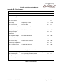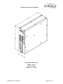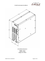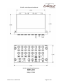
1
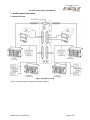
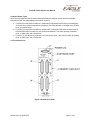
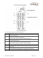
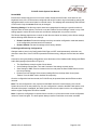
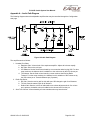
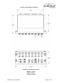
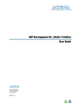
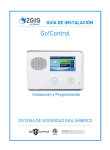
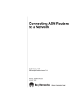
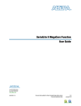
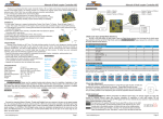
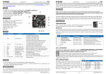
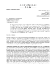
P139-HD Digital Audio System User Manual GA063-3 Revision G 08/25/2015 EAGLE COPTERS USA INC. 19717 62nd Avenue South, Suite E101, Kent WA 98032 | Phone: 800-546-2210 FAX 253-867-5619 www.eaglecopters.com P139-HD Audio System User Manual Revision History Revision Level Date of Revision -- 12-1-09 Initial Release. GA 12-1-09 A 9-16-11 Added Alert Tone web page. GA 9-16-11 B 1-12-12 C 6-25-12 D 4-09-13 E 5-01-14 F 9/29/2014 G 8/25/2015 GA063-3 Rev G 08/25/2015 Description of Change Approval Clarified Configuration Web Page availability. Added G13115/G13116 Control Heads and DO-160 Certification. Added Dimmer web page Added 1-board and 3-board systems. Removed obsolete control heads. Revised company name to Eagle Copters USA. Updated formatting and reorganized. GA 1-12-12 GA 6-25-12 GA 4-09-13 GA 5-01-14 9/29/2014 CLB 8/25/2015 CLB Page 2 of 35 P139-HD Audio System User Manual Table of Contents 1. Introduction ............................................................................................................................................ 5 2. Audio System Description ...................................................................................................................... 6 3. Radio Ports .......................................................................................................................................... 10 4. Headset Ports ...................................................................................................................................... 10 5. Alert Tones ........................................................................................................................................... 11 6. Audio System Emergency Mode Function........................................................................................... 12 7. Control Panels ..................................................................................................................................... 13 8. Setting Radio Volumes ........................................................................................................................ 16 9. Configuration Web Page ...................................................................................................................... 17 10. Troubleshooting .................................................................................................................................. 27 Appendix A – Audio Path Diagram ............................................................................................................. 29 Appendix B – Specifications........................................................................................................................ 30 Appendix C – Environmental Qualifications ................................................................................................ 35 GA063-3 Rev G 08/25/2015 Page 3 of 35 P139-HD Audio System User Manual Figures FIGURE 1 SYSTEM OVERVIEW .......................................................................................................................... 6 FIGURE 2 G13000 FRONT PANEL .................................................................................................................... 7 FIGURE 3 G13160 FRONT PANEL .................................................................................................................... 9 FIGURE 4 CONTROL PANELS .......................................................................................................................... 13 FIGURE 5 CURRENT STATUS PAGE ................................................................................................................. 18 FIGURE 6 HEADSET AUDIO SETTINGS PAGE .................................................................................................... 19 FIGURE 7 UPDATING HARDWARE .................................................................................................................... 20 FIGURE 8 RADIO AUDIO SETTINGS PAGE ........................................................................................................ 21 FIGURE 9 ALERT TONE SETTINGS PAGE ......................................................................................................... 22 FIGURE 10 DIMMER SETTINGS ....................................................................................................................... 24 FIGURE 11 DIMMER VOLTAGE CURVE ............................................................................................................. 25 FIGURE 12 AUDIO PATH DIAGRAM .................................................................................................................. 29 Tables TABLE 1 P139-HD (D) CONNECTORS .............................................................................................................. 8 TABLE 2 P139-HD (S) CONNECTORS ............................................................................................................... 8 TABLE 3 P139-HD (T) CONNECTORS ............................................................................................................. 10 TABLE 4 SPECIFICATIONS............................................................................................................................... 30 TABLE 5 DO-160F QUALIFICATIONS ............................................................................................................... 35 GA063-3 Rev G 08/25/2015 Page 4 of 35 P139-HD Audio System User Manual 1. Introduction 1.1. Description This document describes the general operation of the Eagle Copters P139-HD Digital Audio System. As the P139-HD is highly customizable, this document describes features common to all audio systems. Customer-specific information may be found in the configuration documentation that came with the Audio System. 1.2. Definition of Terms Throughout this document, the term “Radio” applies to any audio device that may be connected to this audio system, even though that device may not be an actual radio. A “Listen-Only” device may be a radio receiver or any type of device that generates an audio signal, such as NAV radios, and warning tone generators. A “Transmit-Only” device, such as a Public Address System, does not provide any receive audio. The unused receive input on a transmit-only channel may be used for an unrelated listen-only device. “Gnet” is the Eagle Copters proprietary network used to communicate with control heads and other Eagle Copters equipment. Each Gnet Bus consists of a two-wire serial data connection, 28V power and Ground. Up to 15 devices may be connected to each bus in a parallel or daisy-chain fashion. Devices are identified by jumpering specific ID pins in the device connector. GA063-3 Rev G 08/25/2015 Page 5 of 35 P139-HD Audio System User Manual 2. Audio System Description 2.1. System Overview Figure 1 System Overview Figure 1 shows the layout of a typical P139-HD (D) system. GA063-3 Rev G 08/25/2015 Page 6 of 35 P139-HD Audio System User Manual 2.2. Audio Router Types There are three types of P139-HD Audio Systems that may be installed. Unless otherwise specified, information in this user guide applies to all models of routers. P139-HD (D) Uses Router G13000 in a “Dual-board” configuration and is shown in the diagrams and is the router used throughout the instructions. This router provides 12 headset ports, 20 radio ports, and 4 Gnet buses. P139-HD (S) Uses Router G13000 in a “Single-board” configuration that uses the same case as the dual-board router, but with only one audio board installed. This router provides 6 headset ports, 10 radio ports, and 2 Gnet buses. P139-HD (T) uses Router G13160 and is a “Three board” router. This router provides 18 headset ports, 30 radio ports, and 6 Gnet buses. 2.3. Front Panel Ports Figure 2 G13000 Front Panel GA063-3 Rev G 08/25/2015 Page 7 of 35 P139-HD Audio System User Manual The P139-HD (D) and (S) Audio Systems consists of a G13000 Digital Audio Router, a number of control panels (type and number of control panels depends on the customers’ configuration) and associated cabling. The P139-HD (T) system uses the G13160 3-board audio router instead of the G13000 router. The G13000 front panel has seven connectors and four LEDs: Port/LED J1 J2 J3 J4 J5 J6 J7 Power LED LED A LEDs B and C Function Radio Ports COM1 and XCVR3 – XCVR11. COM1 and XCVR11 have relays for the Pilot Emergency Isolation Mode. Radio Ports COM2 and XCVR12 – XCVR20. COM2 and XCVR20 have relays for the Co-pilot Emergency Isolation Mode. Pilot Headset and H/S3 – H/S7. Pilot Headset has relays for the Pilot Emergency Isolation Mode and a dedicated COM1 Transmit Keyline. Gnet Ports 1 and 2. Each port may connect to multiple control panels. Co-pilot Headset and H/S3 – H/S7. Co-pilot Headset has relays for the Co-pilot Emergency Isolation Mode and a dedicated COM1 Transmit Keyline. Gnet Ports 3 and 4. Each port may connect to multiple control panels. Power and Ground Connections. Individual control lines for Pilot Emergency Isolation Mode and Co-pilot Emergency Isolation Mode. Two control panel Dimmer input lines. Ethernet port for accessing the Configuration Web Page. Slot for an MMC card containing the Configuration Web Page software and backups of previously-saved configurations. The Audio system will function correctly without an MMC card present, but the Configuration Web Page will not be available. NOTE: MMC card MUST NOT be inserted or removed with the power on. MMC card should be inserted with label facing towards J1. Green when power is applied. System Status LED. Flashes rapidly when system is operating correctly. Status LEDs. May be green or red depending on system status. See Section 10.3 Table 1 P139-HD (D) Connectors In a single board system J1 and J3 connectors and LED B are not installed and J2 and J4 have the following functions: Port J2 J4 Function Radio Ports COM1 and XCVR2 – XCVR10. COM1 and XCVR10 have relays for the Pilot Emergency Isolation Mode. Pilot Headset and H/S2 – H/S6. Pilot Headset has relays for the Pilot Emergency Isolation Mode and a dedicated COM1 Transmit Keyline. Gnet Ports 1 and 2. Each port may connect to multiple control panels. Table 2 P139-HD (S) Connectors Please see drawing G13004 for connector pinouts and cable descriptions. Not all installations will use all ports, please see installation drawings for your system. GA063-3 Rev G 08/25/2015 Page 8 of 35 P139-HD Audio System User Manual Figure 3 G13160 Front Panel The G13160 front panel has nine connectors and five LEDs: Port/LED J1 J2 J3 J4 J5 J6 J7 J8 Function Radio Ports COM1 and XCVR3 – XCVR11. COM1 and XCVR11 have relays for the Pilot Emergency Isolation Mode. Pilot Headset and H/S3 – H/S7. Pilot Headset has relays for the Pilot Emergency Isolation Mode and a dedicated COM1 Transmit Keyline. Gnet Ports 1 and 2. Each port may connect to multiple control panels. Radio Ports COM2 and XCVR12 – XCVR20. COM2 and XCVR20 have relays for the Copilot Emergency Isolation Mode. Co-pilot Headset and H/S8 – H/S12. Co-pilot Headset has relays for the Co-pilot Emergency Isolation Mode and a dedicated COM1 Transmit Keyline. Gnet Ports 3 and 4. Each port may connect to multiple control panels. Radio Ports XCVR21 – XCVR30. Headset Ports H/S13 – H/S18. Gnet Ports 5 and 6. Each port may connect to multiple control panels. Power and Ground Connections. Individual control lines for Pilot Emergency Isolation Mode and Co-pilot Emergency Isolation Mode. Two control panel Dimmer input lines. Ethernet port for accessing the Configuration Web Page. GA063-3 Rev G 08/25/2015 Page 9 of 35 P139-HD Audio System User Manual Port/LED J9 Power LED LED A LEDs B, C and D Function Slot for an MMC card containing the Configuration Web Page software and backups of previously-saved configurations. The Audio system will function correctly without an MMC card present, but the Configuration Web Page will not be available. NOTE: MMC card MUST NOT be inserted or removed with the power on. MMC card should be inserted with label facing towards J5. Green when power is applied. System Status LED. Flashes rapidly when system is operating correctly. Status LEDs. May be green or red depending on system status. See Section 10.3. Table 3 P139-HD (T) Connectors 3. Radio Ports 3.1. Description The P139-HD Audio System has 20 Radio Ports for connecting to external devices. Each Radio Port consists of a Receive (RX) channel from the external device to the P139-HD, a Transmit (TX) channel from P139-HD to external device, and a Keyline that acts as a ground-closure push-to-talk (PTT) switch. The P139-HD (S) has 10 Radio Ports and the P139-HD (T) has 30 Radio Ports. To accommodate devices with different input and output voltage levels, the P139-HD has adjustable levels. More information is given in the Configuration Web Page section. 4. Headset Ports 4.1. Description The P139-HD Audio System has 12 Headset ports. Each port consists of a Microphone (Mic) channel, an Earphone (Ear) channel, an ICS PTT line keyed by an external ground closure switch, and a Transmit PTT line keyed by an external ground closure switch wired directly to the P139-HD Router. The Pilot headset position has a second Transmit PTT keyline that keys the COM1 radio regardless of the settings on the pilot control panel. The Co-pilot headset has a similar keyline to directly key COM2. The P139-HD (S) has 6 Headset Ports and the P139-HD (T) has 18 Headset Ports. GA063-3 Rev G 08/25/2015 Page 10 of 35 P139-HD Audio System User Manual 5. Alert Tones 5.1. Description The P139-HD Audio system supports up to 8 built-in Alert Tones that may be triggered by external events to act as a notification or warning to the crew. External triggers must be a pull-low to ground. When an alert is triggered, the alert will continue to sound until one of the following events occurs: 1. The condition triggering the alert is cleared by the alerting device. 2. The “Alert cancel” button is depressed (if installed). 3. A higher-priority alert is triggered. If the high priority alert is cleared, the low-priority alert will again sound. 4. The alert may be muted while transmitting on a radio, if the alert has been configured to Mute on Transmit. 5.2. Call Indicator The Audio System may be configured for a cabin call indicator using one of the Alert Tone generators. The operation of the Call Indicator is as follows: 1. If a CALL button is pressed, the call tone will be heard by the crew, and the call indicator will flash on the control panel. 2. The call tone and indicator may be cancelled by the deselecting the CALL button. In some installations, deselecting the ICS Isolate function (ISO) from the flight deck control panels also cancels the CALL function. GA063-3 Rev G 08/25/2015 Page 11 of 35 P139-HD Audio System User Manual 6. Audio System Emergency Isolation Mode Function 6.1. Description The Audio System Emergency Isolation Mode Switch allows the pilot(s) to bypass the Audio System and connect directly to the COM radio(s) and aircraft warning audio. Emergency Isolation Mode activates automatically if the G13000/G13160 Audio Router loses power. If the audio system still has power while in Emergency Isolation Mode, Pilot and Co-pilot share a fixed-volume ICS line and individual Voice Recorder audio outputs. Emergency Isolation Mode is controlled by two pins on the power connector (J5 on G13000, J7 on G13160) labelled COM1DIR and COM2DIR for Pilot/COM1 and Co-pilot/COM2 respectively. For a headset to be in normal mode, the Audio Router must have power, be operating normally and the COMnDIR pin must be grounded. If the router does not have power or the COMnDIR pin is not grounded, the router will be in Emergency Isolation Mode. The Pilot and Co-pilot G13115 or G13116 control panels have a locking EMERG/NORMAL toggle switch, which grounds the COMnDIR pin when in the NORMAL position. To enable Emergency Isolation Mode, pull the toggle and move the switch to the EMERG position. This will disconnect the COMnDIR pin from ground. The Pilot EMERG/NORMAL switch MUST be connected to the audio router. If the Co-pilot position will never be used to fly the aircraft the Co-pilot/COM2 Emergency Isolation Mode control line may be grounded to permanently enable Normal mode while the Audio Router has power. The audio system operates as follows depending on switch position: NORMAL In the NORMAL position, the Audio System operates as described in the rest of this document. EMERG (or loss of power to audio system) In the EMERG position the following occurs: 1. The Pilot’s microphone and earphone audio is disconnected from the normal audio system circuits. Mic audio is directly connected to the COM1 radio port transmit audio and Earphone audio is connected to the COM1 and XCVR11 radio port receive audio for aircraft warnings and other important audio. 2. The Pilot’s transmit PTT Keyline and dedicated COM1 transmit PTT keyline are directly connected to the COM1 radio port transmit keyline output. 3. If the audio system still has power the Pilot headset is connected to a fixed-volume emergency intercom bus between Pilot and Co-pilot headset ports. The emergency ICS is keyed by the Pilot ICS PTT keyline. ICS VOX is disabled, and there is no sidetone. 4. If the audio system still has power the Pilot headset audio is duplicated on the XCVR11 transmit audio for use in voice recorder systems. For the Co-pilot position, the Co-pilot EMERG/NORMAL switch performs the same functions between the Co-pilot Headset, COM2 and XCVR20 radio ports. If the P139-HD has power, other Headset Ports will work as normal when the pilots are in Emergency Isolation Mode , except they will not be able to communicate with the Pilot, COM1 and XCVR11 ports and/or Co-pilot, COM2 and XCVR20 ports depending on which pairs are bypassed. A loss of power to the P139-HD will automatically place the system in Emergency Isolation Mode for Pilot and Co-pilot. GA063-3 Rev G 08/25/2015 Page 12 of 35 P139-HD Audio System User Manual G13115NS and G13116NS control panels do not have the EMERG/NORMAL switch installed and may be used at any crew position except the Pilot and Co-pilot. If the Co-pilot position will never be used to fly the aircraft a G13115NS/G13116NS panel may be used. 7. Control Panels 7.1. Description The Audio System may be configured to use any of a number of different control panel types, each specifically configured for a customer’s needs. This manual provides a brief description of the most common types and default operation. Deviations from the standard operation will be detailed in the customer documentation. 7.2. Control Panel Types The following are the most common Control Panel types (See Figure 4): G13115 Control Panel. Usually set up to provide 16 Transmit/Receive Audio Channel selectors, ICS, VOX and Master Volume control. Also has 4 programmable buttons for extra functions, an ICS/Transmit PTT toggle switch and an Emergency Isolation Mode switch. G13116 Control Panel. Usually set up to provide 8 Transmit/Receive Audio Channel selectors, ICS, VOX and Master Volume control. Also has 4 programmable buttons for extra functions, an ICS/Transmit PTT toggle switch and an Emergency Isolation Mode switch. G13116 TX1 TX3 TX2 TX4 TX5 TX6 TX7 TX8 TX1 TX9 TX10 TX11 MULTI RX17 RX18 RX19 TX12 TX13 TX14 TX15 TX16 TX3 TX2 MULTI RX9 RX10 RX11 RX12 RX13 RX14 TX4 TX5 TX6 TX7 TX8 G13116 Control Panel G13115 Control Panel Figure 4 Control Panels GA063-3 Rev G 08/25/2015 Page 13 of 35 P139-HD Audio System User Manual 7.3. Radio Functions Radio transmit and receive select are controlled by a rectangular TX Select button, indicator LED, and a pot/switch directly above it. Transmit operation: 1. To select a radio to transmit on, press the rectangular TX Select button assigned to that radio. The TX Select LED above the button will light. Selecting transmit will also automatically enable receive for that radio regardless of whether the knob (pot/switch) is in or out. 2. To transmit on a radio press the PTT switch assigned to that headset. This control may be on the pilot cyclic, passenger drop cord or footswitch depending on aircraft configuration. 3. Transmit may also be keyed by pressing the ICS/TX toggle switch on the control panel down to the TX position. On control panels serving multiple headsets this function may be disabled. 4. Some installations may have dedicated PTT switches to allow one headset to transmit on a radio without having to select it on the control panel first. Commonly the Pilot has a direct COM1 PTT and the Co-pilot a direct COM2 PTT. 5. The TX LED between the EMERG/NORMAL and ICS/TX switches will light while transmit PTT is active. 6. If a radio has been set with Sidetone Generation enabled (see Configuration Web Page, Section 9.6), then the Audio System will provide sidetone when transmitting. For the person transmitting the sidetone level is fixed (adjustable from the Configuration Web Page) and for others it is adjustable using the ICS Volume pot. Receive Operation: 1. To listen to a radio without selecting it to transmit, press the pot/switch above the TX Select button assigned to that radio so that it is in the Out position. 2. To adjust the radio listen volume, adjust the receive switch/pot. Clockwise increases the volume. 3. To adjust the receive volume level for all radios, turn the MVOL (Master Volume) pot on the bottom-right of the panel clockwise to increase the volume. Certain devices, such as alerts, may have a fixed volume that cannot be adjusted by the MVOL pot. 4. In some configurations, fixed-volume receive-only devices may be assigned to the four multipurpose buttons at the bottom-left of the control panel. Press the button to enable/disable. An LED indicator to the left of the button indicates the listen state. As there is no volume pot, only the MVOL pot has any effect on the volume level in normal operation. This fixed volume may be set in the Configuration Web Page. 5. On G13116 control panels three of the multi-purpose buttons may be set to control two fixedvolume receive-only devices. In Figure 4 an example is the RX11/RX12 button at the bottom left of the control panel. The two LEDs to the left of the button indicate which of the devices is enabled. Pressing the button cycles through the possible combinations e.g. OFF → RX11 → RX12 → BOTH → OFF GA063-3 Rev G 08/25/2015 Page 14 of 35 P139-HD Audio System User Manual 7.4. Intercom Functions Each headset position has Intercom (ICS) function with PTT and voice-activated keying (VOX). Headset positions may be separated into zones (e.g. crew and passengers) that may be isolated from each other if desired. Each control panel has ICS controls for one or more headsets; e.g. a single control panel may control several passenger headsets. 1. To enable ICS, press the ICS switch/pot so that it is in the ‘Out’ position. To disable ICS, press the ICS switch/pot so that it is in the ‘In’ position. 2. ICS volume is controlled by adjusting the ICS switch/pot. Turning the pot clockwise increases the volume. 3. To key ICS, press the ICS PTT switch assigned to that headset. This control may be on the pilot cyclic, passenger drop cord, or footswitch depending on aircraft configuration. 4. ICS may also be keyed by moving the ICS/TX toggle switch on the control panel up to the ICS position. On control panels serving multiple headsets this function may be disabled. 5. The VOX is controlled by the VOX switch/pot. Fully clockwise produces hot mic for intercom. Fully counterclockwise disables VOX, requiring the ICS PTT be keyed to speak over the intercom. Selecting a position between these extremes sets the VOX threshold. The intercom is keyed when the audio from the mic exceeds the VOX threshold set. Pressing the VOX the switch/pot ‘In’ disables VOX. 6. If configured, the ICS may be split into isolated zones by pressing the ISO button. Headsets in one zone will hear ICS from all other headsets in that zone, but not from the other zone. Press the ISO button again to disable isolate. The standard configuration is for two zones. For custom installations with more than ICS two zones, see the configuration information for that system. 7.5. Call Beep If the Call Beep button is selected, the crew will hear a periodic beep. This is commonly used to signal from one Isolated ICS zone to the other. 7.6. Mic Listen For certain configurations, the Audio System may be set to listen to selected crew mics without that crew member keying transmit or ICS. This “Mic Listen” operates in a similar way to a receive-only audio device with a pot/switch. 7.7. Other Functions Due to the customizable nature of the audio system, specific installations may have functions not covered in this guide. Consult the individual configuration for your installation to determine if custom functions have been installed. GA063-3 Rev G 08/25/2015 Page 15 of 35 P139-HD Audio System User Manual 8. Setting Radio Volumes 8.1. Description The audio quality will be greatly diminished if the volume control located on each radio is set too high. Excessive volume from a radio may result in audio crosstalk (bleed-over) and poor audio quality as a result of clipping. This crosstalk may compromise secure communications. 8.2. Procedure It is very important to set the radio volumes in accordance with the following procedure for each radio (and each audio device). Set volume controls on earphones, helmets, and drop cords, to loudest setting Set volume control knobs on the audio panel, including Master Volume knob, to their middle positions (indicator line at 12 o’clock). Adjust the volume control on each radio and other audio device to a comfortable listening level. Once set up as specified above, use only the volume control knobs on the Eagle Copters audio panels to change the volume. Audio Levels should be confirmed every time the audio system is used, and this procedure must be repeated every time the volume level is changed through the Configuration Web Page. GA063-3 Rev G 08/25/2015 Page 16 of 35 P139-HD Audio System User Manual 9. Configuration Web Page 9.1. Description The P139-HD has two levels of configuration: At the factory each unit is set up to the customers’ specific hardware configuration: Number of headsets and radio ports in use, intercom setup, number and type of control panels and function of each control and PTT keyline. In the field, users may adjust volume levels and features of each enabled radio and headset port through a Configuration Web Page in the unit. The Configuration Web Page is accessed by connecting a laptop to the audio router via the Ethernet port, J6. No special software is required and the web page should work with most recent web browsers. 9.2. Network Requirements The P139-HD acts as a DHCP server at address 192.168.0.1. The laptop being connected must be set up that it receives its IP address via DHCP (i.e. not a static IP address) and must not be connected to another network e.g. via WiFi. The Configuration Web Page supports Internet Explorer 6 and higher, Firefox 2 and higher, Safari and Opera. NOTE: The web server in the P139-HD may take about 5 seconds to open each page. In most web browsers, there will be a progress indicator in the address bar or status bar showing the page is loading. Only refresh the page or click on the menu to change pages if the loading indicator shows that the page failed, or it will start the process over and take longer. 9.3. Accessing the Web Page The web page is stored on the MMC card inserted into J7. If the MMC card is not inserted, the audio system will run normally, but the web page will not be available. NOTE: Do not insert or remove the MMC card or Ethernet cable while the Audio System is powered up. To start the web server running on the Audio System: 1. Power down the audio system. 2. Ensure the MMC card is inserted fully into J7 in the correct orientation (label side towards the D50 connectors) 3. Connect a laptop to J6 via the Ethernet cable. The laptop must be powered on and booted before connecting to J6. 4. Power on the audio system. The audio system will detect the MMC card and Ethernet connection and start booting the web server. If either of these is not present the audio system will go into normal mode and the A LED will start flashing within 15 seconds of power up. 5. After about 5 minutes, the A LED will start flashing and the audio system will be operating as normal. Due to the extra load of running the web page, both the flashing of the LED and the response of the control panels will be slower than normal. 6. Open a web browser and enter the address http://192.168.0.1. After a few seconds the Configuration Web Page will load and display the System Status screen. On the P139-HD (T) audio system, the Ethernet port is J8 and the MMC card slot is J9. See Table 3. GA063-3 Rev G 08/25/2015 Page 17 of 35 P139-HD Audio System User Manual 9.4. Status Page The Current Status Page (Figure 5) shows temperature and voltage levels inside the Audio System. The numbers are updated every 10 seconds. The Current Status page also shows the voltage seen by the two dimmer inputs. The control panel brightness for any given input voltage is set by the Dimmer Settings page (see section 9.8). The default setting is 28V being full brightness and 1V being minimum brightness. The default option also sets the dimmer to full brightness when it reads 0V; indicating instrument lights are off for daytime use. Single-cabin aircraft may use only one dimmer channel for all control heads. Larger aircraft may use one channel for the cockpit, and one for the cabin. This is factory set based on individual customers’ requirements. The final item in the System Status list is the 5-digit Configuration Number and customer name. Please quote the Configuration Number when ordering spares, new systems, or discussing configuration changes with Eagle Copters. Figure 5 Current Status Page GA063-3 Rev G 08/25/2015 Page 18 of 35 P139-HD Audio System User Manual 9.5. Headset Audio Settings Page The Headset Audio Settings Page (Figure 6) gives access to the user-adjustable settings for each headset port enabled in the Customer Configuration. Figure 6 Headset Audio Settings Page The grid on the left of the page shows all available headset ports. Ports may be selected by clicking on them. Multiple ports may be selected by clicking on each port while holding down the SHIFT key. Ports that are selected will have a blue background. The following settings may be changed for each headset port: MIC GAIN: Sets the input gain for the headset microphone in dB. Raising the Mic Gain will increase the sensitivity of the microphone. EAR GAIN: Sets the amplifier gain for the earphones in dB. Raising the Ear Gain will increase the maximum volume from the earphone. PRESETS: The drop-down boxes below MIC GAIN and EAR GAIN contain presets for some industrystandard levels. The presets may be overridden by moving the sliders to the desired value, which will set the preset to “Custom”. ICS SIDETONE: Sets the level of sidetone heard in this headset when the user keys ICS. TX SIDSETONE: Sets the level of sidetone heard in the headset when the user keys a Radio for transmit. GA063-3 Rev G 08/25/2015 Page 19 of 35 P139-HD Audio System User Manual Headset Impedance: Sets the expected impedance of the earphone between 150Ω and 600Ω. When set to Track, the audio system will attempt to measure the earphone impedance, and set the output to 150Ω or 600Ω, whichever is closest. When a setting is changed, the web page updates the hardware with the new setting. While this is happening the website will prevent further changes (Figure 7). Note: If the “Updating Hardware” hardware message appears for more than 10 seconds, the update has failed. Close your web browser and power cycle the P139-HD to restart configuration. Any changes that were made but not saved to the MMC in the last session will be lost. See Section 9.9 for more information. Figure 7 Updating Hardware GA063-3 Rev G 08/25/2015 Page 20 of 35 P139-HD Audio System User Manual 9.6. Radio Audio Settings Page The Radio Audio Settings Page (Figure 8) gives access to the user-adjustable settings for each radio port enabled in the Customer Configuration. Figure 8 Radio Audio Settings Page The grid on the left of the page shows all available radio ports. Ports may be selected by clicking on them. Multiple ports may be selected by clicking on each port while holding down the SHIFT key. Ports that are selected will have a blue background. The following settings may be changed for each Radio port: RX GAIN: Sets the input gain on the selected radio ports in dB. Raising the RX GAIN will amplify lowvolume signals. TX GAIN: Sets the amplifier gain for transmit audio (mic) output in dB. Raising the TX GAIN will increase the volume (mic gain) from the audio system to the radio. PRESETS: The drop-down boxes below RX GAIN and TX GAIN contain presets for some industrystandard levels. The presets may be overridden by moving the sliders to the desired value, which will set the preset to “Custom”. Default Volume: If a receiver does not have a volume pot, this sets the default receive volume. If a receiver does have a volume pot, it sets the gain at the center (12 o’clock) position. Use to set the default volume for alert tones or other always-on devices. GA063-3 Rev G 08/25/2015 Page 21 of 35 P139-HD Audio System User Manual Full Duplex: When unchecked, transmitting on this radio will mute the receive audio. When checked, receive will not be muted. Use for satphones or other full-duplex devices or radios where the user must hear setup tones before speaking, or to hear transmit sidetone from the radio. Mute All RX on TX: When checked, transmitting on this radio will mute receive from ALL radios that also have “Mute All RX on TX” checked. Use in situations where radios have RF interference with each other that cannot be solved by other means. Sidetone Generator: When checked, the P139-HD will provide transmit sidetone for this radio. Use with “Full Duplex” unchecked to silence any interference from the radio. When a setting is changed, the web page updates the hardware with the new setting. While this is happening, the website will prevent further changes (Figure 7). 9.7. Alert Tone Settings Page The Alert Tone Settings Page (Figure 9) gives access to the user-adjustable settings for each alert tone enabled in the Customer Configuration. Figure 9 Alert Tone Settings Page GA063-3 Rev G 08/25/2015 Page 22 of 35 P139-HD Audio System User Manual The grid on the left of the page shows all configured Alert Tone generators. Alert Tone generators may be selected by clicking on them. Multiple generators may be selected by clicking on each one while holding down the SHIFT key. Alert Tone generators that are selected will have a blue background. The following settings may be changed for each Alert Tone Generator: Tone Frequency: Sets the frequency of the tone to be played when the alert is triggered. There is special operation for the High/Low tone style. See below. Tone Style: The tone is played in one of the following four styles: Continuous – Continuous beep. On/Off – Repeating ½ second beeps with a ½ second gap between each beep. Intermittent – A group of 3 ½ second beeps, with a 2½ second gap before repeating. High/Low – Tone alternates between the selected frequency and a tone of ½ the selected frequency. For 1000Hz. and 800Hz. the low tone is 600Hz. and for 600Hz. the tone is continuous. Alert Priority: If an alert of lower priority is currently playing, then triggering a higher-priority alert will silence the lower-priority alert, until the higher-priority alert is cleared. Alerts of the same priority will play simultaneously. TONE VOL: Sets the output volume on the selected alert in dB, with 0dB being the maximum volume. Mute on PTT: If this is set, transmitting on any radio will mute the alert tone for the crew member who is transmitting. When a setting is changed, the web page updates the hardware with the new setting. While this is happening, the webpage will prevent further changes (Figure 7). GA063-3 Rev G 08/25/2015 Page 23 of 35 P139-HD Audio System User Manual 9.8. Dimmer Settings Page The Dimmer Settings Page (Figure 10) allows for the adjustment of the voltage-to-brightness curve of each dimmer channel to help match Eagle Copters control panels to existing cockpit lighting. Figure 10 Dimmer Settings The grids show the dimmer information for the two dimmer inputs available on the G13000 connector J5. Router G13160 uses connector J7 for the two dimmer inputs. GA063-3 Rev G 08/25/2015 Page 24 of 35 P139-HD Audio System User Manual Figure 11 Dimmer Voltage Curve The settings page takes three sets of inputs, the desired brightness levels when the instrument panel has been set to minimum, midpoint and maximum brightness. From this the dimmer calculates the brightness level for all other brightness levels as shown in Figure 11. IMPORTANT: Do not select any controls on this page unless setting up the dimmers. If controls are accidentally changed, press the Restore Last Save control to undo the changes. To set up a single dimmer channel: 1. Select the Minimum Brightness control for that channel on the webpage a. Set the dimmer brightness knob in the aircraft to Minimum. The reading at the top-right of the control shows the current dimmer channel voltage. b. Move the Panel Brightness slider until the control panel is at the desired brightness. 2. Select the Midpoint Brightness control on the web page. The Minimum Brightness control freezes the last recorded voltage and brightness settings. a. Set the dimmer brightness knob in the aircraft to Medium Brightness. b. Move the Panel Brightness slider until the control panel is at the desired brightness. 3. Select the Maximum Brightness control on the web page. The Midpoint Brightness control freezes the last recorded voltage and brightness settings. a. Set the dimmer brightness knob in the aircraft to Maximum. b. Move the Panel Brightness slider until the control panel is at the desired brightness. 4. Off is Full Brightness checkbox determines if the control panels should go to 100% brightness if the dimmer channel voltage falls to zero. This is used when the cockpit lights are turned off in daytime and as an additional safety if the aircraft dimmer bus fails. GA063-3 Rev G 08/25/2015 Page 25 of 35 P139-HD Audio System User Manual Normal/NVG: Each dimmer channel may be set in one of two modes, Normal and NVG mode, each with their own brightness levels. If the P139 has been configured with an NVG mode it may be selected by pushing the appropriate switch on the control panel or external control. The webpage will automatically select Normal or NVG mode. Only the current mode may be changed. Restoring Settings: If the dimmer controls have been changed and reverting to a previous version is required, there are three options. The first is to use the “Restore Previous Settings” control on any of the settings pages to restore all audio, alert tone and dimmer settings back to a previous version. The Dimmer Settings page has two controls on each dimmer channel to restore just the dimmer settings without affecting audio and alert tone settings: Restore Last Save: Reverts the settings to as they were when configuration mode was started, or the configuration was last saved in this session. Restore Defaults: Reverts the settings to their factory defaults. 9.9. Saving and Restoring Configurations Changes made to ports in the Configuration Web Page are NOT saved permanently unless the user chooses to save them. If the P139-HD is powered off without saving, changes since the last save will be lost. Controls for saving and loading configurations are at the bottom of the Headset Audio Settings and Radio Audio Settings pages (See bottom of Figure 8). The Save/Restore controls consist of three boxes: Active Settings: Shows Date, Time and Comment of the settings currently active. Save Settings to MMC: Enter a comment in the box and press the Save to MMC button to store the current settings. Restore Previous Settings: Select a saved settings file from the drop-down list and press “Restore” from the MMC card to load the file temporarily. Once the configuration has been saved, the P139-HD may be powered down and the Ethernet cable removed. Note: The new configuration is only copied from the MMC card to the internal memory of the Audio System when the unit is next powered up. If a new configuration is saved to the MMC card and the card removed before power is reapplied, the Audio System will not have copied over the new configuration, and the original configuration will still be installed. Note: If a previous configuration is restored from the archive, it will not become the current configuration unless it is saved out again. The audio system always uses the file with the most recent save date. GA063-3 Rev G 08/25/2015 Page 26 of 35 P139-HD Audio System User Manual 9.10. Configuration File Storage When the P139-HD configuration is changed, a copy is saved on the MMC card as two files: config.yam config.md5 These files (and all files on the MMC) should NEVER be modified by the user. If you require technical support or a major configuration change not available through the Configuration Web Page, these two files should be copied from the MMC card and emailed to Eagle Copters, to preserve any settings you have changed on the web page. 10. Troubleshooting 10.1. Description The P139-HD Audio System is customized to individual customer requirements, and depending on the installation this may make some operational features different from as described in this manual. This section gives a brief overview of possible control settings that might make the Audio System not operate as expected, and some basic troubleshooting procedures. 10.2. Power LED The Power LED will light up if there is power to the Audio System and one of the internal voltage regulators is working. The Configuration Web Page may be used to check the voltages on all the internal power supplies on the audio system. 10.3. Status LEDs The P139-HD has three Status LEDs, labeled A, B and C. These LEDs have different meanings depending on the status of the Audio System. The A LED is the main status LED for the Audio System: On power up the LED changes color from red to green several times. If power up is successful, the LED flashes green at high speed. If there is a fault, the LED will be steady red. This is usually caused by problems with loading a new configuration or firmware upgrade from the MMC. The B and C LEDs have two functions: 10.4. On power up the B and C LEDs will be off while the P139-HD searches for configuration or firmware updates. The two LEDs will turn green once any updates have been loaded. If there is a fault, the two LEDs will be steady red, along with the A LED. Once the system is operating (A LED flashing green), the LEDs act as a ‘peak indicator’ for audio inputs. If the mic inputs on J1 or receive inputs on J3 are loud enough to cause audio clipping, the B LED will turn red. Inputs on J2 and J4 will set the C LED red. Functional Checks If the Audio System does not appear to be working correctly, please check the following: Audio System Emergency Isolation Mode Switches should be set in the ‘Normal’ position. Ensure ICS is not Disabled or Isolated. Ensure Radio Volumes are set as described in Section 8. GA063-3 Rev G 08/25/2015 Page 27 of 35 P139-HD Audio System User Manual 10.5. Accessing the Configuration Web Page The P139-HD will only boot into Configuration mode if it sees a working network connection. The P139HD must be connected to the computer and the computer powered up before powering up the P139-HD. If the boot sequence halts with a green or red “A” LED that is not flashing, then the MMC card may have come unseated during flight. Remove and reinsert the MMC card in J7. The P139-HD will automatically detect the speed of the Ethernet connection, and determine if a crossover or straight cable is being used. To do this the connecting computer must also be set to auto detect speed and duplex. This is usually enabled as standard, and may be checked on Windows computers by looking at the properties of the network adapter in Device Manager and checking the “Speed” setting on the “Advanced” tab. This should be set to “Auto”. GA063-3 Rev G 08/25/2015 Page 28 of 35 P139-HD Audio System User Manual Appendix A – Audio Path Diagram The following diagram shows the adjustable amplifiers that may be controlled through the Configuration web page. Figure 12 Audio Path Diagram The amplifiers work as follows: 1. Headset Port Gains: a. Earphone Gain: Volume level of the earphone amplifier. Adjusts all volumes equally. b. Mic Gain: Gain on the mic input. c. ICS Sidetone: Set the fixed volume heard by a crew member when keying ICS. For other crew members, the sidetone level is added on to the volume set by the ICS volume pot. d. TX Sidetone: Set the fixed volume heard by a crew member when keying Radio Transmit. For other crew members, the sidetone level is added on to the volume set by the ICS volume pot or Transmit Sidetone pot (if present) 2. Radio Port Gains: a. RX Gain: Sets the receive gain for this radio port. Will change the gain for all listeners. b. TX Gain: Sets the transmit gain for all listeners. c. Default Gain: Sets the volume of radios without a volume adjustment knob. If a volume pot is present, the default volume is added to the volume level from the pot. 3. Alert Tone Volume: Volume heard by all crew members who may hear the alert. GA063-3 Rev G 08/25/2015 Page 29 of 35 P139-HD Audio System User Manual Appendix B – Specifications Parameter Conditions Value Unit Max. Input Voltage 60 V DC Min. Input Voltage 12 V DC Max. Input Current 5 A Min. Input Current 1 A Electrical Characteristics Gnet Voltage Supplied by G13000 24 V DC Max. Gnet Current Per Gnet bus 0.5 A Max. Dimmer voltage DC, AC or PWM input. 28 V 4.5 dBV 500 Ω 13.5 dBV Audio Characteristics Max. Microphone Input MIC GAIN set to minimum Microphone Input Impedance Max. Earphone Output EAR GAIN at maximum Expected Earphone 150 or Impedance Max. Receive Input 600 RX GAIN set to minimum Receive Input Impedance Max. Transmit Output Ω TX GAIN at maximum Expected Transmit 14.0 dBV 600 Ω 6.0 dBV 150 Ω Impedance Keyline Characteristics Headset PTT Key Voltage Keyline must be pulled below this value to key 0.5 V Max. Radio Keyline Pull-up voltage provided by radio 28 V 1 A Voltage Max. Radio Keyline Current Table 4 Specifications GA063-3 Rev G 08/25/2015 Page 30 of 35 P139-HD Audio System User Manual G13000 Router Dimensions Weight = 5.0 lbs Power = 5 amps Voltage = 14 – 32 VDC GA063-3 Rev G 08/25/2015 Page 31 of 35 P139-HD Audio System User Manual G13160 Router Dimensions Weight = 5.3 lbs Power = 5 amps Voltage = 14 – 32 VDC GA063-3 Rev G 08/25/2015 Page 32 of 35 P139-HD Audio System User Manual G13115 Control Panel Dimensions Weight = 1.5 lbs Power = 250 mA Voltage = 28 VDC GA063-3 Rev G 08/25/2015 Page 33 of 35 P139-HD Audio System User Manual G13116 Control Panel Dimensions Weight = 1.25 lbs Power = 250 mA Voltage = 28 VDC GA063-3 Rev G 08/25/2015 Page 34 of 35 P139-HD Audio System User Manual Appendix C – Environmental Qualifications DO-160F Environmental Cat. D1C4XXBAAU2(F)(F1)XXXXXXZBXXBBZCTTMA3D3XXXXXXAX DO-160F Env. Cat. Section Category Description Temp/Alt 4.0 D1C4 Low Temperature 4.0 D1C4 High Temperature 4.0 D1C4 Loss of Cooling 4.5.4 Z Equipment tested to Category D1 (50,000ft , non-pressurized, controlled temperature) and C4 (35,000ft, non-pressurized, noncontrolled temperature) Operating Temp: -20°C Short-Time Operating: -40°C Ground Survival: -55°C Operating Temp: +55°C Short-Time Operating: +70°C Ground Survival: +85°C No Cooling Required Temp. Variation 5.0 B 5°C minimum per minute Humidity 6.0 A Equipment tested to Category A Shock 7.0 A 6G in any direction Vibration 8.0 U2 Equipment tested to Category U2 (Robust Vibration Test) Explosion 9.0 X Equipment identified as Category X – no test required Waterproof 10.0 X Equipment identified as Category X – no test required Fluids 11.0 X Equipment identified as Category X – no test required Sand/Dust 12.0 X Equipment identified as Category X – no test required Fungus 13.0 X Equipment identified as Category X – no test required Salt Fog 14.0 X Equipment identified as Category X – no test required Mag Effect 15.0 Z Less than 0.3m Power Input 16.0 B Equipment tested to Category B Voltage Spike 17.0 B Equipment tested to Category B Conducted Audio 18.0 B Equipment tested to Category B Induced Signal Susceptibility RF Susceptibility 19.0 ZC Equipment tested to Category ZC 20.0 TT Equipment tested to Category TT RF Emissions 21.0 M Equipment tested to Category M Lightning Induced 22.0 A3D3 Equipment tested to Category A3D3 Lightning Direct 23.0 XXXX Equipment identified as Category X – no test required Icing 24.0 X Equipment identified as Category X – no test required ESD 25.0 A Equipment tested to Category A Fire 26.0 X Equipment identified as Category X – no test required Table 5 DO-160F Qualifications GA063-3 Rev G 08/25/2015 Page 35 of 35