1
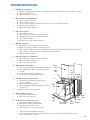
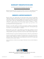
U S E
&
C A R E
Waterwise 7000
™
Water Distiller
See important safeguards on page 2
An exclamation point within an equilateral triangle is intended to alert
user to the presence of important operating and maintenance instructions
in the literature accompanying the appliance.
A lightning bolt within an equilateral triangle is intended to alert user to
risk of injury from electric shock.
Water and steam vapor within an equilateral triangle is intended to alert
user to risk of injury from boiling water and/or escaping steam.
G U I D E
IMPORTANT SAFEGUARDS
A person who has not read and understood all operating and safety instructions is not qualified to operate this appliance. When using this appliance, always adhere to basic safety precautions including:
R EAD ALL INSTRUCTIONS BEFORE USE.
FOR COMMERCIAL AND HOUSEHOLD USE.
located on louvered cover). The cord has a three-
pronged plug which mates with a standard three-pronged grounded outlet. DO NOT cut or remove third prong from plug. If an adapter is
used, be sure adapter wire and wall outlet are grounded. If there is any doubt about the outlet being properly grounded, check with a qualified electrician.
10.DO NOT operate with a damaged cord or plug, after a malfunction, or if Distiller has been dam-
aged in any manner. Return to an authorized ser vice facility for examination, repair, or replacement. Unplug from wall outlet when not in use and before cleaning.
11. This Distiller is recommended for use with potable water only. DO NOT attempt to make
safe drinking water from non-potable water source.
DO NOT use briny (sea) water as this will dam age certain components and will void warranty.
12. Keep Distiller in a well-ventilated area and away from other heat sources, providing adequate air space (at least 4-6 inches from walls or cabinets). DO NOT place on or near a hot gas or electric burner, or in a heated oven. DO NOT store or stack anything on top of or against sides of
Distiller while in operation.
13.DO NOT operate Distiller without water in the boiler tank. Permanent damage may occur.
14. This Distiller requires no special care other than periodic filter replacement (page 6) and general cleaning (page 10). If servicing becomes necessary, please contact your authorized dealer or qualified service facility. There are NO user serviceable parts. See warranty for service details.
15. Make sure “Power” and “Fan” switches are off and gasket, boiler tank and lid are properly secured before plugging in Distiller.
16.DO NOT use the Distiller for other than the intended use.
1. Operate indoors on a dry, level, well-supported, stable surface. DO NOT use outdoors. DO NOT operate in a moving vehicle.
2.
DO NOT allow children to be near Distiller with-
out close supervision. Boiling water will scald if spilled on skin. Warn other users of possible dan-
gers from boiling water and/or escaping steam.
3. Never remove boiler while Distiller is operating. Let cool at least one hour after a cycle is finished or interrupted. Boiling water or steam can cause severe burns.
4.
DO NOT change position or location of Distiller while it is operating or cooling. Wait at least one hour after a cycle is finished or interrupted before moving Distiller. Boiling water or steam can cause severe burns.
5.
DO NOT place near an edge of a surface where Distiller can be bumped or pulled down on some-
one. DO NOT allow power cord or extension cord to hang over the edge of a counter or contact hot surfaces.
6. A short power supply cord is provided to reduce risks resulting from becoming entangled in or tripping over a longer cord. If an extension cord must be used, its marked electrical rating should be at least as great as electrical rating of Distiller. Electrical rating is found on louvered cover.
7.
DO NOT touch hot surfaces. Distiller gets very warm during use. Allow to cool before cleaning.
8. To protect against fire, electrical shock, and injury to persons, DO NOT immerse power cord or Distiller in water or liquid.
9. Plug Distiller into a properly rated voltage AC grounded electric outlet ONLY (rated voltage label This product was tested and certified by the Water Quality Association against WQA S-400 for the reduction of TDS
(Total Dissolved Solids) and structural integrity.
Cycle
Production
Operating
Operation
Model V=Volts Hz=Hertz W=Watts AMPS
Time
Rate
Pressure
Temperature
gpd =
1 gallon
gallons per day
40°-110°F
7050
120V
60Hz
1200W
10AMPS 2.75 hrs
9 gpd
20-80 psi
5°-45°C
40°-110°F
7052
230V
50Hz
1100W
4.8AMPS 2.75 hrs
9 gpd
20-80 psi
5°-45°C
2
Electric Cord Statement
CAUTION: Your Distiller has a short cord as a safety precaution to prevent injury or property damage resulting from
pulling, tripping or becoming entangled with the cord. Do not allow children to be near this Distiller without close
adult supervision. If you must use an extension cord with this Distiller, the cord must be arranged so that it will not
drape or hang over the edge of a countertop or tabletop where it can be pulled on by children or tripped over. To prevent electric
shock, injury or fire, the electrical rating of the extension cord you use must be the same as or more than wattage of the Distiller
(wattage is indicated on the louvered cover of the Distiller). Plug Distiller into rated voltage AC grounded electric outlet ONLY
(rated voltage found on louvered cover). The cord has a three-prong plug which mates with a standard three-prong grounded
wall outlet. Do not cut or remove the third prong from the plug. If an adapter is used, be sure adapter wire and wall outlet are
grounded. If there is any doubt as to whether the outlet is properly grounded, check with a licensed electrician. Unplug the Distiller when not in use.
SAVE THESE INSTRUCTIONS
How It Works
Figure A
This Distiller produces purified water by using the oldest,
most effective method of water treatment—steam distillation.
When the Distiller is operating, the water temperature rises to
212°F (100°C), killing bacteria, cysts, and viruses that may be
present. As the boiling water 1 converts to steam 2 , it rises
and leaves behind dead microbes, dissolved solids, salts, heavy
metals, and other substances. Low boiling light gases that may
be present are discharged through the gaseous vent 3 . Steam
is then cooled in the stainless steel condenser 4 , turning it
into high quality water. Distilled water percolates through a
final polishing coconut shell carbon filter 5 to enhance quality by adsorption of VOCs (volatile organic compounds), and
is then collected in the stainless steel reservoir 6 .
3
UNPACKING
The Waterwise 7000 is packaged to prevent damage in shipping. If any damage is found, immediately notify the carrier who made delivery and/or the company from which it was purchased. After opening box and removing Distiller, lift hinged cover to boiler tank area and remove ALL packing material.
NOTE: Each Distiller is individually tested to
ensure high quality standards. Water residue (deposits) may be evident in the boiler tank as a result of this quality control procedure.
INSTALLATION
REQUIREMENTS
Reservoir Plug
PREPARING FOR FIRST TIME USE
Initial
Cleaning
Clean inside of reservoir with either hydrogen peroxide or a paste of baking soda and water. Rinse thoroughly.
Reservoir
Assembly
3 Gallon Model
Several factors should be considered when choosing the best location:
• A properly rated voltage AC grounded electric outlet is required (rated voltage label located on louvered cover). If uncertain whether the outlet is properly grounded, have it checked by a quali-
fied electrician.
• A well-ventilated area is necessary to properly dissipate heat produced during the distillation process. When using your Distiller, provide
adequate air space above and on all sides for air
circulation (especially louvered half where fan motor is located). Keep at least 4-6 inches from walls or cabinets.
• Locate your Distiller near a pressurized water source. Twenty-five (25) feet of 1/4” inlet tubing and a saddle valve are included to tap into a
COLD water pipe for automatic fill. Optional water connector available: utility faucet con nection for 3/4” hose thread type faucet.
• The location should also provide easy and con venient dispensing of the distilled water.
Figure B
• For your added convenience, the optional Remote Faucet Pump System provides distilled water on tap and to an automatic refrigerator icemaker.
Black Plastic Jam Nut
1. To install black adhesive-backed feet to bottom corners of reservoir, position reservoir so that it
sits open side down. Peel and stick adhesive feet (provided) to outside corners of reservoir bottom. To ensure better adhesion, wipe bottom corners of reservoir with alcohol before installing feet. Turn reservoir over so that it sits open side up
(fig. B).
2. Decide if you wish to mount sight gauge faucet on either the wide or narrow side of the reservoir. Install sight gauge faucet by placing
one rubber washer (flat side against outside of reservoir) onto threaded end of the faucet. Insert faucet through the mounting hole in reservoir. From INSIDE reservoir, secure with black plastic jam nut. DO NOT OVERTIGHTEN. Inspect to make sure sight gauge is straight.
3. Install the reservoir plug by placing one rubber washer (flat side against outside of reservoir), onto threaded end of plug and inserting it into the remaining hole in reservoir (fig. B). From INSIDE reservoir, secure with black plastic jam nut. DO NOT OVERTIGHTEN.
Sight Gauge
4
Rubber Washer
Sight Gauge
Faucet
Reservoir
Assembly
8 Gallon Model
Reservoir
Assembly
12 Gallon Model
1.
2.
3.
To install plastic feet, place reservoir on the floor, open side down, so legs are pointing up.
Install a plastic foot on bottom of each leg. Turn reservoir over so that it stands open side up (fig. C).
Decide if you wish to mount sight gauge faucet on either the wide or narrow side of the reservoir. Install sight gauge faucet by placing
one rubber washer (flat side against outside of reservoir) onto threaded end of the faucet. Insert faucet through the mounting hole in reservoir. From INSIDE reservoir, secure with black plastic jam nut. DO NOT OVERTIGHTEN. Inspect to make sure sight gauge is straight. Position sight gauge retaining bracket over sight gauge and hook it over edge of reservoir (fig. C).
NOTE: If installing a Remote Faucet Pump System, please refer to Remote Faucet Pump System Use and Care Guide in order to complete reservoir assembly.
1.
2.
3.
4.
5.
4. Install reservoir plug by placing one rubber washer
(flat side against outside of reservoir), onto thread-
ed end of plug and inserting it into the remaining
hole in reservoir (fig. C). From INSIDE reservoir, secure with black plastic jam nut. DO NOT OVERTIGHTEN.
Figure C
Sight Gauge
Retaining Bracket
Figure D
To install casters, place reservoir on the floor, open side down, so legs are pointing up.
Install both caster support assemblies onto reser-
voir legs by inserting the raised steel tabs on caster support assembly into open end of legs. Securely fasten caster support assemblies in place using bolts provided (fig. D).
Install the four black plastic end caps by insert-
ing an end cap into each open end of the caster support assembly by hand and then tapping into place using a rubber mallet (fig. D).
Install the four casters into holes provided on caster support assembly. Tighten securely. Turn reservoir over so that it stands open side up
(fig. D).
Decide if you wish to mount sight gauge faucet on either the wide or narrow side of the reservoir. Install sight gauge faucet by placing
one rubber washer (flat side against outside of reservoir) onto threaded end of the faucet. Insert faucet through the mounting hole in reservoir. From INSIDE reservoir, secure with black plastic jam nut. DO NOT OVERTIGHTEN. Inspect to make sure sight gauge is straight. Position sight gauge retaining bracket over sight gauge and hook it over edge of reservoir (fig. D).
Black Plastic
Jam Nut
Sight Gauge
Retaining Bracket
Black Plastic
Jam Nut
Sight
Gauge
Sight
Gauge
Sight
Gauge
Faucet
Reservoir
Plug
Sight
Gauge
Faucet
Reservoir
Plug
Rubber
Washer
Rubber
Washer
Caster Support
Assembly
Black Plastic Foot
Locking Swivel
Caster
Black Plastic
End Cap
5
NOTE: If installing a Remote Faucet Pump System, please refer to Remote Faucet Pump
System Use and Care Guide in order to complete reservoir assembly.
6. Install reservoir plug by placing one rubber washer
(flat side against outside of reservoir), onto thread-
ed end of plug and inserting it into the remaining
hole in reservoir (fig. D). From INSIDE reservoir, secure with black plastic jam nut. DO NOT OVERTIGHTEN.
Carbon
Pre and PostTreatment
Prefilter (optional):
Carbon pretreatment consists of an in-line filter housing
and a two-stage spun fiber and organic coconut-shell carbon filter cartridge. Pretreatment removes suspended particles to reduce maintenance and ensure more troublefree operation. Carbon also improves the purity of the distilled water by significantly reducing substances such as benzene, chlorine, chloroform, pesticides, etc., that are found in some tap water. Cartridge should be
replaced about once a year. For installation instructions, see Form 7812 included with the in-line filter housing.
to have an unwanted taste or odor. Order replacement filters from the outlet where you purchased your Distiller.
NOTE: This Distiller meets the listing require-
ments of Underwriters Laboratories Inc. but
they have not investigated the physiological effect of the use of these carbon filters, beneficial or otherwise.
Operational maintenance and replacement requirements are essential for this product to perform as advertised.
Placing
Distiller on Reservoir
Set Distiller on top of reservoir (fig. E). Be sure to locate louvered half (where fan motor is located) over post filter end of reservoir. DO NOT install post filter until reser-
voir has been sterilized.
Figure E
Hinged
Cover
Louvered
Cover
Post Filter (optional):
An activated carbon post filter made from organic coconut shell enhances the taste and purity of the dis-
tilled water by significantly reducing possible carryover of substances such as benzene, chlorine, chloroform,
pesticides, etc. that may be present in some tap water.
Replace every 60-80 gallons distilled or every two months, whichever comes first.
Sterilize and Rinse Carbon Filter Cup
Before installing, fully immerse new filter cup in distilled water for about five minutes. Then sterilize filter cup by fully immersing in boiling water for about five minutes. Allow filter to cool before handling. Pour 1 to 2 cups of distilled water through filter cup to rinse away any small, harmless carbon fines (dust). Water draining from the filter cup may contain black dust. This is typical. The carbon dust is formed as a result of production, packag-
ing and shipping of filter cup.
NOTE: Set prepared filter cup aside until reservoir has been steam sterilized (page 9).
6
Replace Filter Cup
The filter cup should be replaced every two months or
after 60-80 gallons of water processed (whichever comes first). Replace more often should the distilled water begin Reservoir
Post Filter
Holder
Remove and Clean Boiler Tank
1.
2.
Unplug boiler tank cord from receptacle (fig.G).
Unscrew and remove black knob by turning coun-
terclockwise. Raise lid and lift boiler tank up and off of lift spring bracket. Lid stays attached to unit.
IMPORTANT: DO NOT immerse boiler tank in water or other liquid.
3. Using a sponge or cloth, clean interior of boiler
tank with hot soapy water. Rinse thoroughly.
Reinstall
Boiler Tank
CAUTION: To avoid personal injury or property damage, be certain Distiller is unplugged before installing boiler.
1. Place hook of the boiler tank over the lift spring bracket located on front half of Distiller (fig. F).
2. Be sure gasket on boiler is securely in place.
3. Fit lid with attached tubes over gasket and onto boiler tank making sure threaded center support protrudes through hole in lid.
4. Secure lid by turning black knob clockwise.
5.
IMPORTANT: Make sure boiler tank moves down when pressing down on top of tank. The tank should spring up when it is released (fig. G).
6.
Be sure to fully insert boiler tank cord plug into receptacle so the indicator line is NOT visible(fig G). A loose connection may damage tank cord and receptacle; thus resulting in Distiller failure.
Figure F
Lift Spring Bracket
Gasket
WATER SUPPLY
CONNECTION
Installation
NOTE: All state, provincial and local laws and regulations must be followed in the installation and use of your distiller.
Turn inlet elbow fitting assembly clockwise onto inlet water valve (fig. H). Cut the inlet tubing square and remove any burrs. Firmly push the tubing into the elbow fitting. Pull on the tubing to check that it is secure inside the fitting. If secure, insert red clip between fitting body
and collet.
IMPORTANT: If you will be using a prefilter, install it now. See Prefilter Installation Instructions
(form 7812).
CAUTION: DO NOT position tubing over sharp objects which could cut tubing or near any equipment, appliances, etc. that generate excessive heat which could melt tubing.
Saddle
Hook
Figure G
Valve
The supplied saddle valve taps into a COLD water pipe under your kitchen sink, near washing machine or other suitable location and fits 3/8” outside diameter (OD) up to 1-1/4” OD soft or hard tubing or pipe.
Figure H
Hinged
Cover
Black
Knob
Tank
Cord
Plug
Lid
Inlet
Water
Valve
Elbow
Fitting
Assembly
Receptacle
Indicator
Line
Collet
Boiler
Tank
Boiler
Tank
Cord
Tubing
Fan
Switch
Thermal Overload
Reset Switch
Clip
Power
Switch
Lift
Spring
Float Ball
Bracket
7
Installing
Saddle Valve on Copper Installing
Saddle Valve on Steel or PVC Pipe
Pipe
IMPORTANT: DO NOT use a hot water supply.
IMPORTANT: DO NOT use a hot water supply.
1. Assemble saddle valve on COLD water pipe with two (2) bolts (fig. I). Be sure piercing lance does not protrude beyond the sealing washer.
2. Tighten bolts evenly with saddle clamp brackets parallel. DO NOT OVERTIGHTEN.
3. Slide compression nut over end of 1/4” tubing. Place white compression ring on tubing. Be sure wide end of ring is facing compression nut
(fig. I). Insert brass tube support into end of
tubing. Insert tubing into valve and hold firmly
in place while threading nut onto saddle valve. Tighten with a wrench.
4. Turn handle clockwise as far as possible. The
copper pipe is now pierced and valve is closed.
5. To open valve, turn handle counterclockwise as far as possible.
6. Check for leaks. Retighten compression nut if necessary.
1. Shut off main water supply and drain pipe.
2. Drill a 5/32” diameter hole in COLD water pipe.
Use a hand drill to avoid shock hazard.
3. Turn handle to expose piercing lance 3/16”
beyond the sealing washer.
4. Assemble saddle valve on COLD water pipe so piercing lance fits into hole.
5. Tighten bolts evenly with saddle clamp brackets parallel. DO NOT OVERTIGHTEN.
6. Slide compression nut over end of 1/4” tubing. Place white compression ring on tubing. Be sure
wide end of ring is facing compression nut
(fig. I). Insert brass tube support into end of tub-
ing. Insert tubing into valve and hold firmly in place while threading nut onto saddle valve. Tighten with a wrench.
7. Turn handle clockwise to close valve.
8. Open main water supply.
9. To open valve, turn handle counterclockwise as far as possible.
10. Check for leaks. Retighten compression nut if
necessary.
Bolts
Figure I
Brass Tube Support
Handle
White Compression Ring
Compression Nut
Valve
1/4” Tubing
Piercing Lance
Sealing Washer
To Distiller
Cold Water Pipe
Saddle Clamp Bracket
8
Utility
Faucet Connection (optional)
For 3/4” male threaded faucet (fig. J).
Installation
1. Turn off COLD water faucet.
2. Disconnect any appliance hose from faucet.
3. Insert rubber washer into brass body.
4. Screw brass body onto faucet.
5. Screw valve into threaded hole on brass body.
Tighten with wrench.
6. Slide compression nut over end of 1/4” tubing. Place white compression ring on tubing. Be sure wide end of ring is facing compression nut (fig. J). Insert brass tube support into end of tubing. Insert tubing into valve and hold firmly in place while threading nut onto valve. Tighten with a wrench.
7. Reconnect appliance hose to brass body. A cap (not included) is needed if there are no hose reconnects.
8. Turn on COLD water faucet.
9. To open valve, turn handle counterclockwise.
10. Check for leaks. Retighten compression nut if necessary.
Figure J
Cold
Water Supply
Faucet
Valve
Rubber Washer
Brass Body
White Compression
Ring
Brass Tube
Support
Compression Nut
1/4” Tubing
Appliance Hose
To Distiller
STEAM STERILIZATION
Steam
Sterilization for First Time Use
NOTE: Prior to first time use, a steam steriliza tion procedure is recommended. If Remote Faucet Pump System is installed, disconnect tubing from reservoir elbow fitting before steam sterilizing.
1. Plug power cord into properly rated voltage AC grounded electric outlet. Turn “Power” switch on. Leave “Fan” switch in “OFF” postion. You should hear water begin to fill the boiler tank.
2. When sufficient water fills the boiler tank, heating element will turn on automatically. After 15-20 minutes, you should notice steam beginning to appear in the sight gauge.
CAUTION: External surfaces will be HOT dur-
ing this process. DO NOT TOUCH UNIT.
3. Continue steaming process for an additional 15
minutes. Condensation on outside of reservoir is normal during this process.
4. Turn off “Power” switch and allow unit to cool completely.
5. When Distiller has cooled completely, unplug power cord. Install prepared carbon post filter cup into post filter holder in reservoir (fig E).
USING THE DISTILLER
Operational maintenance and replacement requirements are essential for this product to perform as advertised.
1. Before you start your Distiller, be sure the water supply is open to the Distiller.
2. Lift the hinged boiler tank cover and check for pro per mounting of boiler by pressing down. The tank should spring up when it is released (fig. G).
3. Be sure “Fan” and “Power” switches are off before plugging power cord into outlet (fig. G). Plug the three-pronged power cord into a properly rated voltage AC grounded electric outlet only.
4. Press the two switches (“Fan” and “Power”) to the “ON” position—red indicator showing.
5. Boiler tank will start to fill with water.
6. As the water level rises in boiler tank, the fan and heating element will automatically turn on.
7. The water inlet valve controls flow of water into the boiler tank. Distiller will continue to operate until storage reservoir is filled with distilled water. The reservoir float system turns Distiller off auto matically. Distiller will not restart until sufficient water has been drawn from the reservoir.
NOTE: To interrupt operation, simply press “Power” switch to “OFF” position.
9
DISTILLER
MAINTENANCE
IMPORTANT: To avoid personal injury, unplug
boiler tank cord only after “Fan” and “Power” switches (fig. G) are turned off, Distiller is
unplugged from wall outlet, and unit has com-
pletely cooled.
Boiler
Tank
Empty the water out of boiler tank after every 15-20 gal
lons of water distilled or weekly, whichever comes first.
To empty boiler, press “Fan” and “Power” switches to “OFF”position. Unplug main power cord from wall outlet. Unplug boiler tank cord. Unscrew and remove black knob and raise lid. Lift boiler tank up and off of lift spring bracket. Lid stays attached to unit (fig. F).
Empty the contents and rinse any loose scale deposits from boiler.
IMPORTANT: DO NOT immerse boiler tank in water or other liquid.
Remount boiler tank onto lift spring bracket (fig. F). Check for proper mounting by pressing boiler tank down. It should spring up when released. Be sure to fully insert boiler tank cord plug into receptacle so the indicator line is NOT visible. A loose connection
may damage tank cord and receptacle; thus resulting in Distiller failure. Plug main power cord into wall outlet, press “Fan” and “Power” switches to “ON”
position. Approximately every three to four weeks, a
thorough removal of scale deposits may be necessary. Cleaning frequency will vary depending on usage and water conditions.
To dissolve scale deposits, remove, empty and rinse boiler tank. Fill with approximately 1 gallon of KLEENWISE
solution or another safe mineral solvent. Be sure to
follow descaling instructions on product label.
Descaling time will vary depending on strength of descaler/solvent and amount of scale buildup. After cleaning, rinse boiler tank thoroughly and remount. DO NOT remount boiler tank until cleaning proce
dure is complete.
NOTE: DO NOT use abrasive cleaners, caustic acids or steel wool pads. DO NOT scrape or chisel scale from boiler tank.
10
Condensing
Coil
The condensing coil fins should be cleaned periodically. A dirt/dust deposit will decrease efficiency of Distiller. Condensing coil maintenance should be done by autho-
rized personnel only (see Owner’s Limited Warranty).
Reservoir
To clean reservoir, remove carbon filter cup and empty any water. Clean with either hydrogen peroxide or a paste of baking soda and water. Rinse thoroughly and steam sterilize (page 9). The higher the room tempera-
ture, the more often reservoir should be cleaned; how-
ever, the reservoir should be cleaned at least every six months.
NOTE: If Remote Faucet Pump is installed, disconnect tubing from reservoir elbow fitting before cleaning the reservoir.
Exterior
Surfaces
To maintain the exterior surfaces of Distiller, wipe with a soft, damp cloth. The exterior stainless steel surfaces may be cleaned with stainless steel polish.
TROUBLESHOOTING
1.Distiller does not operate.
A. Distiller is not plugged into properly rated voltage AC grounded electrical outlet or circuit breaker is tripped.
B. “Power” switch is not on.
C. Water connection is not open.
2.Boiler tank does not fill with water.
A. Water connection is not open.
B. “Power” switch is not on.
C. Storage reservoir is full. Draw sufficient water out of reservoir to activate float switch.
D. Inlet water valve is defective.*
E. Water microswitch is defective.*
3.Fan does not operate.
A. “Fan” switch is not on.
B. Boiler tank is not mounted on lift spring bracket.
C. Insufficient water in boiler to activate microswitch.
D. “Fan” switch is defective.*
E. Fan motor or fan microswitch is defective.*
4.Water does not boil.
A. Boiler tank is not mounted on lift spring bracket.
B. Make sure tank plug is fully inserted into receptacle.
C. “Reset” button on side of boiler tank tripped, breaking the circuit. Be sure boiler tank is clean. Press “Reset” button. If “Reset” button continues to trip, thermal overload defective.*
D. Heating element is defective.*
5.Inlet water valve does not shut off.**
A. Boiler tank is not mounted on lift spring bracket.
B. Water microswitch is defective.*
C. Inlet water valve is defective.*
6.Water leak in boiler tank area.
A. Lid is not properly aligned or black knob not tightened.
B. Boiler tank gasket is defective or not properly fitted
on tank.
C. O-ring in knob is missing or defective.
D. O-ring around heating element is defective.*
Hinged
Cover
Black
Knob
Tank
Cord
Plug
Lid
7.Distilled water has an unusual taste.
A. Contaminated carbon filter(s). Replace the pre
and/or post filter(s).
B. Boiler needs cleaning (page 10).
Boiler
C. Boiler overfilling (see 5 above, Inlet water valve does
Tank
not shut off).**
D. Reservoir needs cleaning (page 10).
8.Water overflows reservoir.**
A. Float microswitch is defective.*
B. Inlet water valve is defective.*
9.Condensation on outside of reservoir.
A. Normal while steam sterilizing unit.
B. Inadequate ventilation around Distiller.
C. Excessive dust on condenser coil.*
D. “Fan” switch not on or fan motor defective.
Boiler
Tank
Cord
Receptacle
Indicator
Line
Power
Fan Switch
Switch
Thermal Overload
Reset Switch
Lift
Spring
Float Ball
Bracket
* Call your authorized distributor for service.
** If raw water has entered reservoir, clean and sterilize reservoir (page 9) and change post filter (page 6)
after problem has been corrected.
11
WARRANTY REGISTRATION CARD
Please fill out and return the enclosed registration card or register online at
http://www.waterwise.com/customers/customers.asp
Registration will not affect warranty coverage but may expedite processing of your warranty. Registration is the
only way to guarantee you will be notified by Waterwise of any issues that arise concerning this product.
OWNER’S LIMITED WARRANTY
Waterwise warrants, to the original purchaser, this product against defects in materials and workmanship,
excluding the disposable carbon filter and gasket, for a period of two (2) years from the date of purchase on all
electrical and non-stainless steel components and fifteen (15) years from the date of purchase on all stainless
steel parts. Defects or failures due to shipping/handling, incorrect installation, improper use or maintenance,
including abuse or neglect, normal wear, water conditions, accidents, alterations or modifications, or unauthorized repair are specifically excluded from this warranty. No dealer, distributor, agent, representative, or other
person is authorized to extend or expand this warranty.
Waterwise is not responsible or liable for personal injury, property damage, or incidental or consequential damages arising out of, or in connection with, the use or performance of the product or other damages with respect
to loss of use, or costs of removal, installation, or reinstallation.
Waterwise will, at its option, replace or repair the defective part(s) without charge, provided they are returned,
transportation prepaid by owner, to an authorized service facility or to the address below. Enclose a letter describing the problem, copy of dated proof of purchase, and your name, address and daytime telephone number.
This limited warranty does not guarantee uninterrupted service. Repair or replacement as provided under this
warranty is the exclusive remedy of the purchaser. This limited warranty is in lieu of all other warranties,
expressed or implied, including, but not limited to, any implied warranty of merchantability or fitness for a
particular use or purpose. This warranty gives you specific legal rights and you may also have other rights which
vary from state to state or province to province.
Outside the United States, a different warranty may apply. For details, please contact your authorized Waterwise
distributor.
3608 Parkway Blvd • Leesburg Florida 34748-9399 • (352) 787-5008 • Fax: (352) 787-8123
www.waterwise.com • E-mail: [email protected]
© 1990 Waterwise Inc
Printed in USA
Form 7801 • L20120WT • Rev 02/11