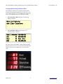
1
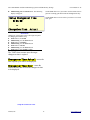
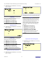
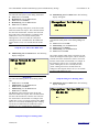
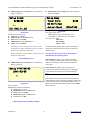
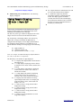
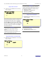
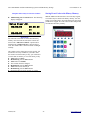
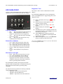
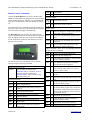
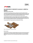
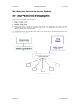
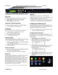
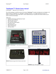
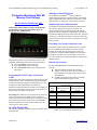
DC117B6-PROD1 Production Monitoring System with SD Memory Storage User manual V1.2F Running or Static/Shift Goals Production Monitoring With SD Memory Card Storage The Production TimeKeeperTM allows production monitoring using running, or static/shift goals. The running goal is calculated from the TAKT time and Lot Size count while the static, or shift goal is easily entered by the user. The Production TimeKeeper TM Monitor and Save Production Data The Production TimeKeeperTM monitors production and conveniently displays the results as a deviation, and percentage between the production goal and the amount actually produced. In addition to monitoring production the Production TimeKeeperTM also tracks down-time, and other critical time events like the number of times the TAKT time expired. All of this data is stored in a conveniently accessible history memory. TAKT timer with production counter and production statistic history storage that will monitor up to 10 production lines simultaneously. Recording User Events or Reason Codes Sometimes specific events occur that need to be recorded that are in addition to the standard events. This system includes an external port to permit special events to be recorded. For example: Machine jammed, out of material, lunch break, fire drill, service door opened, or any other event. The events can be entered manually or directly from a machine output. This reference guide covers the firmware Version V1.2F production monitoring system for the following products. DC117B6-PROD1 with 1 serial port. DC117BB-PROD1 with 2 serial ports. DC117BB-PROD1-MP3 with 2 serial ports and MP3 player. Buttons and Controls The DC117B6-PROD1 has the following buttons and controls: The main unit has 6 buttons and one knob. The RJ11 jack on the side of the unit connects to remote buttons or machine inputs for Run, Pause, Programmable TAKT Timer and Lot Size Stop and Next. In addition, optional remote buttons or machine Count inputs can be added for special events. Traditionally, TAKT time is the time it takes to fabricate and ship one product, and is established by dividing the number of orders in hand by the number of working hours in a day. Front Panel Buttons In addition to the programmable TAKT timer, the TM Production TimeKeeper also contains a user-settable Lot Button Momentary Press and Press and Hold for 2 Size counter which allows the user to set the TAKT time to Name Release seconds the time it takes to fabricate product lots. Processing lots. TAKT times of less than one second do not work well with this system. When it takes less than one second to process one production unit, it is advisable to setup the system to process in lots. In this case, set the Lot Size factor to a standard lot size and set the TAKT time to the correct time to process one lot. DC117B6-PROD1-MP3 The MP3 option adds the capability to play audio files stored on the SD card. Alzatex, Inc 1 Save History Display SD Card File Name. Display history. Recall Run/Pause/ Stop Mode Recall stored setting. Run/pause production counter Toggle display modes. Select Cycle knob function. Save History Memory to SD Card. Store history and reset production counter to zero. Save stored setting. Stop the Production Timer. Select various setup choices. Diagnostic Modes Table 2. DC117B6-PROD1 button reference www.alzatex.com DC117B6-PROD1 Production Monitoring System with SD Memory Storage While in changeover mode: - Momentary Pressing start puts system into RUNNING mode. Same as remote input two. - Press and hold start puts system into STOPPED mode. Same as remote input three. Remote Inputs Remote inputs on the RJ-11 connector on the side of the unit Remote Operation Input Input 1 Run Input 2 Changeover Input 3 Stop Input 4 Increment (Next) Effect on Effect on Effect on Actual TAKT Changeover Count Timer Timer runs pauses pauses None pauses runs pauses None User manual V1.2F While in stopped mode: - Momentary Pressing start puts system into RUNNING mode. Same as remote input two. - Press and hold start puts system into STOPPED mode. Same as remote input three. None None None Increments the count by the Lot Size factor Serial data Input Table 3. Remote input function reference RS-422 Serial data input for input from additional devices of input from a PLC or computer. A detailed list of commands is described in the programming manual. Serial data Output RS-422 Serial data output for operating displays, and on indicators, alarms, PLC or computer. The remote inputs are ground closure type. The Run, Pause (ChangeOver) and Stop inputs are typically connected to operator buttons. The Increment (Next) button may be a button for the operator or may be connected directly to a machine trigger. Operating Modes The system will be in one of the following operating modes: Running. The TAKT timer is running. Stopped. All timers are stopped. Downtime. The TAKT timer is running and the Down timer is running. Changeover. The Setup timer is running. While in stopped, downtime or changeover mode: - Pressing start puts system into RUNNING mode. Same as remote input one. While in running mode: - Momentary Pressing start puts system into DOWNTIME mode. (PAUSE) - Press and hold start puts system into CHANGEOVER mode. While in downtime mode: - Momentary Pressing start puts system into RUNNING mode. Same as remote input two. - Press and hold start puts system into STOPPED mode. Alzatex, Inc 2 www.alzatex.com DC117B6-PROD1 Production Monitoring System with SD Memory Storage User manual V1.2F Changeover / Setup Time Monitoring Production Statistics 2. The Production Timekeeper™ can display the current production Data which is available on various screens. Momentarily pressing the Mode button toggles between the screens. The screen in step one is normally displayed during production monitoring. Momentarily press the Mode button again. Another four-line display similar to the following display will appear: Setup Time HH:MM:SS Accum Setup HH:MM:SS ------------ SetupGrn ChangeOverTm HH:MM:SS Description Line 1 – Actual Changeover (Setup) time for this event. (Count-up) Line 2 – Accumulated Changeover (Setup) time. (Count-up) Line 3 – Status (run/ setup/ down/ stop) Line 4 – Changeover time remaining for this event. (Count-down) Warning and Blink Count Example display showing the current production data. This 3. display includes a speaker that permits audio messages to be played from MP3 files stored on the SD card. You must have the DC117BB-PROD1-MP3 model to play audio files. Act Target and Actual 1. Momentarily press the Mode button again. Another four-line display similar to the following display will appear: Momentarily press the Mode button. A four-line display similar to the following display will appear: Goal nnnnnn HH:MM:SS Act nnnnnn HH:MM:SS Dev nnnnnn Run Eff nnnn nnnnnn RateDly Auto Blnk nnnnnn 0 Yel nnnnnn Run Grn Red nnnnnn SetClock Description Line 1 – actual count; Rate delay, Mode: Auto/Off Line 2 – Yellow blink count, Rate delay value. Line 3 – Yellow warning count, Status (run/ setup/ down/ stop) Line 4 – Red warning count (TAKT time expired) Grn HH:MM:SS Description Line 1 – Goal count; TAKT time (count down) Line 2 – Actual count; actual time (count up) Line 3 – Deviation; Status (run/ setup/ down/ stop) Line 4 – Efficiency; Time of day Alzatex, Inc 3 www.alzatex.com DC117B6-PROD1 Production Monitoring System with SD Memory Storage The individual production line counting feature requires either additional external hardware or connection to a PLC. Actual Count by Hour or Production Line 4. User manual V1.2F Momentarily press the Mode button again. This display Up Time and Down Time serves one of two purposes depending on the system configuration. By default, when using IN4 on the remote port to increment the production count, these counters 6. Momentarily press the Mode button again. Another show the production count for every hour of the day four-line display similar to the following display will over a 24 hour period where 1=1AM, 2=2AM, etc appear: throughout the entire day. Alternatively, with additional equipment to increment the production count, these AccumUpTime HH:MM:SS counters can keep track of the production counts from multiple production lines. When counting production AccumDnTime HH:MM:SS from multiple lines simultaneously, the actual count for UpEf 100 Run Grn individual lines will be recorded. Another four-line display similar to the following display will appear: DownTime HH:MM:SS Line Actual 4 98453 1 2345 5 56232 2 2433 6 12987 3 9432 7 29845 Description Line 1 – Accumulated Up time for for the current shift. Line 2 – Accumulated Down time for for the current shift. Line 3 – Percent efficiency 0 to 100 percent of Up time verses down time, Status (run/ setup/ down/ stop). Line 4 – Actual downtime for the current event. Description Line 1 – Production Hour Actual or Line Actual Line 2 – Line number, Actual count Line 3 – Line number, Actual count Line 4 – Line number, Actual count The individual production line counting feature requires either additional external hardware or connection to a PLC. Seconds Gained/Lost Per Wigit Made Grand Total Target and Actual Count 7. 5. Momentarily press the Mode button again. This display shows the Grand totals for up to 24 production lines. Each time the actual counters are reset, the actual count is added to the grand total. Another four-line display similar to the following display will appear: Momentarily press the Mode button again. Another four-line display similar to the following display will appear: Cgan 22 Gain Clos 0 Lost Totals: Goal Actual Tgan 120 1 33241 151203 Tlos 82 2 23447 12527 3 7922 61845 Description Line 1 – Seconds less than the TAKT time for the current wigit built. Line 2 – Seconds greater than the TAKT time for the current wigit built. Line 3 – Accumulated Seconds less than the TAKT time for the current shift. Line 4 – Accumulated Seconds greater than the TAKT time for the current shift. Description Line 1 – Totals: Goal Actual Line 2 – Line number, Goal Count, Actual count Line 3 – Line number, Goal Count, Actual count Line 4 – Line number, Goal Count, Actual count Alzatex, Inc Seconds 4 www.alzatex.com DC117B6-PROD1 Production Monitoring System with SD Memory Storage Performance Results in a given Time Period 8. Momentarily press the Mode button again. Another four-line display similar to the following display will appear: Performance Results Tcnt 1200 Acnt 1255 Description Line 1 – Title Line 2 – Target count for the current time period. Line 3 – Actual count for the current time period. Line 4 – Not used. Analyzing and Improving productivity There are three warning counts called Yellow Blink (Blnk), Yellow Warning (Yel) and Red Warning (Red). These warnings can be used to indicate whether the actual time is longer or shorter than the TAKT time and determine whether there is a problem with production or whether a particular operator is slower or faster or whether the TAKT time is too long or too short. User manual V1.2F The Yellow Blink (Blnk) warning indicates the number of times the Yellow Blink time was reached before the TAKT time expired to complete a production unit. If the TAKT time is 100 seconds and the Yellow Blink time is 20 seconds, then this count will be incremented if it takes 80 or more seconds to complete a production unit. The Yellow (Yel) warning indicates the number of times the Yellow Warning time was reached before the TAKT time expired to complete a production unit. If the TAKT time is 100 seconds and the Yellow Warning time is 10 seconds, then this count will be incremented if it takes 90 or more seconds to complete a production unit. The Red (Red) warning indicates the number of times it took longer than the TAKT time to complete a production unit. The status field indicates the operational mode of the unit. Run Grn Run Yel Run Red Changeover (Setup) Down Time Stopped One of several error messages may appear on the lower right corner of the display. SetClock Indicating that the time of day clock needs to be set. ClkError Indicating that there is a problem with the TIME of day clock. LowBatt Indicating that the battery needs to be replaced. The battery can be replaced by removing the rear cover and replacing the battery with a new CR2032 coin cell type battery. Ideally, the TAKT time should be set such that the yellow blink count and the yellow warning count increments the same as the actual count, but that the Red warning count always remains at zero. The production workers can observe the Green-Yellow-Red Andon indicators to determine whether they are ahead or behind the expected TAKT time. These indicators are great for Slide-Lines where several production workers need to synchronize together. Alzatex, Inc 5 www.alzatex.com DC117B6-PROD1 Production Monitoring System with SD Memory Storage User manual V1.2F Storing and Resetting Production Data The Production Timekeeper™ will save production data each time the Production Timekeeper™ is reset. The events 0 to 11 shown in table 1 are saved, and then the counters are reset to zero and the timers are set to their preset values. 1. Press and Hold the History button. The following display will appear: Save to History and Clear Counters 2. Press and Hold the History button again. The following display will appear: Goal nnnnnn HH:MM:SS Act 0 00:00:00 Dev 0 Run Eff 0 HH:MM:SS Grn The Goal, Actual, Yellow Blink, Yellow Warning and Red Warning counters are set to zero. The Actual time and Down time is reset to zero. The TAKT time is set to the preset value. Alzatex, Inc 6 www.alzatex.com DC117B6-PROD1 Production Monitoring System with SD Memory Storage User manual V1.2F Table of Event Codes 18 ---- Reserved for future use. The following data can be stored. The time and date is saved along with each history entry. 19 ---- Reserved for future use. 20 Gpre Current static/shift goal. The event codes are also used by the “Setup Remote Display” menu for output data to a remote display. 21 Scal Current Lot Size factor. The following events and/or data are stored whenever the Save to History and Clear Counters command is executed. The following events are recorded whenever one of the remote inputs Run, Pause, Stop or Next is activated. The recording of these events can be individually enabled or disabled using the Setup Event Save menu. Event Name Description Event 0 Goal Production goal count. This can be either a running, or static goal. 22 Run The RUN mode was started. The value field will be the downtime in seconds. 1 Act Actual production count. This can be incremented manually, or by machine. 23 Paus The RUN mode was paused. The value field will be the actual time in seconds. 2 Dev Deviation count. (Goal – Actual). 24 Stop 3 Eff Efficiency percent. (Goal/Deviation*100) The RUN mode was stopped. The value field will be the actual time in seconds. 4 Down Accumulated Machine Down Time in seconds. 25 Wigi 5 Takt TAKT time in seconds. A new unit is completed. The value field will be the actual time in seconds to complete this wigit. 6 Time Actual Time since the current wigit was started. This value is in seconds. Other Events. 7 Red Red warning indicator count. This indicator occurs after the TAKT time has expired. 27 Save 8 Yel Yellow warning indicator count. This indicator occurs during the TAKT time prior to the red warning indicator. When this occurs is user-programmable. The history memory was saved to the SD card. The value field contains the number of entries stored. 28 Clr 9 Blnk Yellow blink indicator count. This indicator occurs during the TAKT time prior to the red warning indicator. When this occurs is user-programmable. The history memory was cleared. The value field contains the number entries in the history memory at the time it was cleared. 29 Key A remote “KPn command was received. The 'n' is the value portion of the event. 30 TOD Display the time of day clock. 10 Time Actual count for the current hour 31 Rcll Recall a stored setting. 11 Tset Total accumulated changeover (Setup) time in seconds. 32 Sser Save data to external device connected to the serial port. 12 ---- Reserved for future use. 33 Tgoa Grand total Goal Count 13 Cgoa Goal Changeover (Setup) Time. 34 Tact Grand total Actual Count 14 Cact Actual Changeover (Setup) time for the current event. 35 UpTm Accumulated up time. 15 Cdev Deviation between the goal and actual changeover (Setup) time in seconds. 36 UpEf Accumulated up time verses down time efficiency. 16 Ceff Efficiency of the current changeover (Setup) time represented as a percentage. 37 Time Time remaining to build the current wigit. Changes to actual time, if the time remaining is zero. This value is in seconds. 17 ---- Reserved for future use. Alzatex, Inc Description Event 7 Description www.alzatex.com DC117B6-PROD1 Production Monitoring System with SD Memory Storage 38 Cact Changeover time remaining for the current event. Changes to actual Changeover (Setup) time if the time remaining is zero. This value is in seconds. 39 Evnt Event code 0 to 99,999 40 Cgan Number of seconds gained for the current wigit. 41 Clos Number of seconds lost for the current wigit. 42 Tgan Total accumulated seconds gained since last shift. 43 Tlos Total accumulated seconds lost since last shift. 44 --- Reserved for future use. 45 --- Reserved for future use. 46 --- Reserved for future use. 47 --- Reserved for future use. 48 Acnt Target count for the previous time period since last time the performance values were reset. 49 Tcnt Actual count for the previous time period since last time the performance values were reset. User manual V1.2F The following events and/or data are stored whenever the Save to History and Clear Counters command is executed. The following values are recorded when storing the actual counter values for production lines 1 through production line 24. These actual counters are incremented when one of the external “KP0 through “KP9 commands are received. 60-73 AC00 Actual count values for production line 1 to AC00 (60) through production line 24 AC23 AC23 (73). 74-255 --- Alzatex, Inc Reserved for future use. 8 www.alzatex.com DC117B6-PROD1 Production Monitoring System with SD Memory Storage User manual V1.2F Clearing the History memory Clearing the Grand Totals To reset the production timers and counters: To reset the production timers and counters: 3. 6. 4. 5. Press and Hold the History button. The following display will appear: Press and Hold the History button. The following display will appear: Save to History Save to History and Clear Counters and Clear Counters 7. Turn the Knob a number of clicks until the “Clear History Memory” message appears in the display. Press and Hold the History button again. The following display will appear: 8. Clear Grand Totals Clear History Memory Empty Empty The entire history memory is cleared. A single message is added “Clr 341” where the number is the number of history entries that was in the history memory before it was cleared. Alzatex, Inc Turn the Knob a number of clicks until the “Clear Grand Totals” message appears in the display. Press and Hold the History button again. The following display will appear: 9 The grand totals are cleared. Two messages for each production line that had an actual count greater than zero are added to the history memory. The “Tgoa 12661” which is the goal grand total count and .the “Tact 12962” which is the actual grand total count . www.alzatex.com DC117B6-PROD1 Production Monitoring System with SD Memory Storage User manual V1.2F Recalling Stored Production Data Selecting the Static/Shift or Running Goal Modes The Production Timekeeper™ can recall stored production data. The values shown in table 1 are monitored, and then stored each time the Production Timekeeper™ is reset: The Production Timekeeper™ provides two different methods for management of Goal values: Note: The Production Timekeeper™ has a history memory of 4095 entries. This means that the Production Timekeeper™ can often times store many days of production data. • In the running goal mode, the Production Timekeeper™ calculates the running goal. It does this by adding the Lot Size count to the goal count each time the takt time expires. • In the static/shift goal mode, the user enters the desired goal count as a preset value. In this mode, that value does not change until the user reconfigures it. To recall production data: 1. Momentarily press the History button. A four-line display similar to the following display will appear: 2008/01/12 14:03:45 0 Goal nnnnnn 9 1 Act 12 nnnnnn History In either mode, the DC117B6-PROD1 will display the goal count, the actual count, the calculated deviation between the goal and actual counts, and the calculated efficiency (the percentage of actual production versus the production goal). The reader board displays the goal count, the actual count, and the efficiency. 12 NOTE: To select a running goal, the preset goal count must be set to 0. Any non-zero preset goal count will remain the static goal value.. Only a preset goal count of zero changes the goal calculation mode of the Production Timekeeper™ from static/shift mode to running mode. Of 156 Note: The first line is the date and time. The second and third lines are 2 lines of historical data. The fourth line is the number of history entries and the total number of history entries. 1. Turn the knob to scroll through the production history. As you scroll, the window will show 4 entries in sequence. It helps to think of the 4-line display as a sliding window over the history memory that rolls over to the beginning when it gets to the end. LOC 00 01 02 03 04 05 06 07 08 09 10 . . . 31 Event Display Value 0 Save 76 4 Down 4398 5 TAKT 122 2007/10/22 1 Act 03 9 Grn -- 2. 3. Description. 4. 08:22:54 9 line 1 line 2 18 line 3 History 4 of 156 0 Goal 44 6 Time 4567 4 Down 4422 5 TAKT 288 5. line 4 6. When starting a new shift or new production run, Press and hold the History button to clear the counters and reset the timers. Momentarily press the Run/Changeover/Stop button on the DC117B6-PROD1 unit or press the remote Run button (remote input IN1) to start the TAKT, and actual timers. The TAKT timer will auto-restart when it expires. Increment the production actual count by pressing the Next button (remote input IN4). See the following Remote Inputs section for details. For unscheduled production stoppages, machine repairs or whenever you want downtime to accumulate, pause the TAKT and actual timers by momentarily pressing the Run/Changeover/Stop button on the DC117B6PROD1. For Changeovers or other setups, press the remote Pause button (remote input IN2) . Resume the timers by momentarily pressing the Run/Changeover/Stop button on the DC117B6PROD1, or press the remote Run button (remote input IN1). See the following Remote Inputs section for details. NOTE: the Run/Changeover/Stop button is labeled as Run/Stop on the unit. Alzatex, Inc 10 www.alzatex.com DC117B6-PROD1 Production Monitoring System with SD Memory Storage Note: Whenever the Production Timekeeper™ is in the changeover mode the TAKT and actual timers are paused and the setup time timer starts running. 2. 3. User manual V1.2F Turn the knob to select the desired 0 to 3 location. Press and hold the Recall Setting button again to store the current Production Timekeeper™ setup into the selected storage location. Note: Whenever the Production Timekeeper™ is in the downtime mode the downtime timer starts running. In addition, the TAKT timer continues to run. When the unit is resumed the downtime and/or setup timer is paused and the TAKT timer and actual timer is resumed. 7. For scheduled breaks or shift changes, Stop the TAKT and actual timers without starting the downtime timer pressing the press and holding the Run/Stop button or press the remote Stop button (remote input, IN3). Recalling a Setup To recall a setup: 1. Momentarily press the Recall Setting button. The following display will appear: Setup Recall 3 User Programmable Presets ^^ The Production Timekeeper™ can save and recall 4 user programmable setups. Each stored setup is labeled from 0 to 3, and contains the following items: 1. 2. 3. 4. 5. 6. 7. 8. 9. 10. 11. 12. TAKT time. TAKT Time Mode. Goal Target Value. Scale factor / Lot Size. TAKT Timer Yellow blink time. TAKT Timer Yellow warning time. Beeper mode. Rate Setpoint. Changeover Target Time. Changeover Time Mode. Changeover Yellow blink time. Changeover Yellow warning time. 2. 3. Turn the knob to select the desired 0 to 3 setup. Momentarily press the Recall Setting button again to recall the Production Timekeeper™ setup from the selected storage location. Storing a Setup To store a setup: 1. Press and hold the Recall Setting button. The following display will appear: Setup Store 3 ^^ Alzatex, Inc 11 www.alzatex.com DC117B6-PROD1 Production Monitoring System with SD Memory Storage User manual V1.2F Setup the Changeover Time Setting Up the Production Timekeeper™ The Production Timekeeper™ contains user programmable timers and counters. Each programmable setting is selected using the Mode button, and modified using the Select button and the knob. To setup the Production Timekeeper™: Setup the TAKT Time Press and hold the Mode button. The following display will appear: Setup TAKT Time 00:01:00 ^^ Cycle Time Actual Instructions Sets the TAKT timer. Turn knob to set seconds Momentarily press the Select button Turn knob to set minutes Momentarily press the Select button Turn knob to set hours Momentarily press the Select button Turn knob to select either Actual or Over Cycle Time Actual causes the total elapsed cycle time to be displayed. Cycle Time Over causes the amount of time that exceeds the cycle time to be displayed. Alzatex, Inc 12 www.alzatex.com DC117B6-PROD1 Production Monitoring System with SD Memory Storage Momentarily press the Mode button. The following display will appear: User manual V1.2F Set the Goal value to 0 if you want to use the TAKT timer to generate a running goal that increments throughout the day. Set the Goal value to a fixed value if you want to set a fixed static goal. Setup Changeover Time 0:01:00 ^^ ChangeOverTime Actual Instructions Changeover or Setup time. This is the target setup time for changing the machine setup. Turn knob to set seconds Momentarily press the Select button Turn knob to set minutes Momentarily press the Select button Turn knob to set hours Momentarily press the Select button Turn knob to select Actual or Over The TAKT timer resumes once the target changeover time is expired. ChangeoverTime Actual causes the total elapsed cycle time to be displayed. ChangeoverTime Over causes the amount of time that exceeds the changeover time to be displayed. Setup the Goal Preset Value Alzatex, Inc 13 www.alzatex.com DC117B6-PROD1 Production Monitoring System with SD Memory Storage Momentarily press the Mode button. The following display will appear: Setup Lot Size 1 Setup Goal Gpre User manual V1.2F 0 ^^ Goal ^^ Actual NOTE: Do not set the Lot Size to 0. If you set the Lot Size to 0, the Next button will never increment the actual count. Instructions Keep at 0 if a running goal is desired. If a static goal is desired, set this value to the desired goal. Turn knob to set goal in steps of 1 Momentarily press the Select button Turn knob to set goal in steps of 100 Momentarily press the Select button Turn knob to set goal in steps of 10000 Instructions The actual count increments by the Lot Size count. The running goal calculation also uses the Lot Size count. You can select whether the actual count, the goal count or both are affected by the Lot Size factor. For instance, if you have the goal count, but not the actual count selected, the goal will increment in steps of the Lot Size factor, while the actual count increments in steps of one. Turn knob to set goal in steps of 1 Momentarily press the Select button Turn knob to set goal in steps of 100 Momentarily press the Select button Turn knob to set goal in steps of 10000 Momentarily press the Select button Turn knob to select whether the Lot Size factor affects the actual count, goal count, both or neither. Setup the Line Goal Momentarily press the Mode button. The following display will appear: Setup Line Goal 0 ^^ Line 1 Instructions Keep at 0 if a running goal is desired. If a static goal is desired, set this value to the desired goal. Turn knob to set goal in steps of 1 Momentarily press the Select button Turn knob to set goal in steps of 100 Momentarily press the Select button Turn knob to set goal in steps of 10000 Momentarily press the Select button Turn knob to select production line 2 Repeat the above five steps for this line. Repeat for subsequent lines until all lines are setup. Setup the TAKT Timer Warning Times Momentarily press the Mode button. The following display will appear: Setup Yel Warning 0:00:04 ^^ Setup the TAKT Timer Lot Size Factor Momentarily press the Mode button. The following display will appear: Alzatex, Inc 14 www.alzatex.com DC117B6-PROD1 Production Monitoring System with SD Memory Storage Instructions Sets when the solid yellow occurs during TAKT time. Turn knob to set seconds Momentarily press the Select button Turn knob to set minutes Momentarily press the Select button Turn knob to set hours Momentarily press the Mode button. The following display will appear: ChangeOver Yel Warning 00:00:20 The yellow warning (solid yellow) occurs the set time before the TAKT time expires. This is measured from the start of the Actual timer, which is reset each time the Actual count is incremented. For example: If the TAKT time is set to 14 seconds, and the yellow warning time is set to 4 seconds, the solid yellow warning will occur 4 seconds before the TAKT time expires which is 14-4, or 10 seconds into the Actual time. ^^ Instructions Sets when the solid yellow occurs during Changeover time. Turn knob to set seconds Momentarily press the Select button Turn knob to set minutes Momentarily press the Select button Turn knob to set hours Setup the Cycle Time Yellow Blink Time User manual V1.2F Momentarily press the Mode button. The following display will appear: The yellow warning (solid yellow) occurs the set time before the Changeover time expires. This is measured from the start of the Actual timer, which is reset each time the Actual count is incremented. For example: If the Changeover time is set to 14 seconds, and the yellow warning time is set to 4 seconds, the solid yellow warning will occur 4 seconds before the Changeover time expires which is 14-4, or 10 seconds into the Actual changeover time. Setup Yellow Blink 0:00:07 ^^ Instructions Sets when the blinking yellow occurs during TAKT time. 1. Turn knob to set seconds 2. Momentarily press the Select button 3. Turn knob to set minutes 4. Momentarily press the Select button 5. Turn knob to set hours The Blinking Yellow warning occurs the set time before the TAKT time expires. This is measured from the start of the Actual timer, which is reset each time the Actual count is incremented. For example: If the TAKT time is set to 14 seconds, and the Yellow Blink time is set to 8 seconds, the Blinking Yellow warning will occur 8 seconds before the TAKT time expires which is 14-8, or 6 seconds into the Actual time. Setup the Changeover Warning Times Momentarily press the Mode button. The following display will appear: ChangeOver Yellow Blink 00:00:40 ^^ Setup the Changeover Warning Times Alzatex, Inc 15 www.alzatex.com DC117B6-PROD1 Production Monitoring System with SD Memory Storage Instructions Sets when the blinking yellow occurs during Changeover time. 6. Turn knob to set seconds 7. Momentarily press the Select button 8. Turn knob to set minutes 9. Momentarily press the Select button 10. Turn knob to set hours The Blinking Yellow warning occurs the set time before the Changeover time expires. This is measured from the start of the Actual timer, which is reset each time the Actual count is incremented. For example: If the Changeover time is set to 14 seconds, and the Yellow Blink time is set to 8 seconds, the Blinking Yellow warning will occur 8 seconds before the Changeover time expires which is 14-8, or 6 seconds into the Actual changeover time. User manual V1.2F Setup the Time Of Day Clock Setup the Rate Setpoint Momentarily press the Mode button. The following display will appear: Setup Rate Setpoint 0 ^^ Instructions Keep at 0 if the rate delay feature is not used. When operating a high rate production line that typically never stops, the up timer runs. When no pulses are detected on the count input for the specified number of seconds, the down timer starts running. Turn knob to set the rate delay from 1 to 255 seconds. Turn knob to set the rate delay to 0 to disable this feature. Alzatex, Inc 16 www.alzatex.com DC117B6-PROD1 Production Monitoring System with SD Memory Storage Momentarily press the Mode button. The following display will appear: Setup Clock User manual V1.2F Momentarily press the Mode button. The following display will appear: Setup Beep 0:00:00 Timer Zero 0:00 On Warnings ^^ Actual<Goal DC117B6-V1.2B Instructions Sets up the beeper mode. 1. Turn knob to select the desired mode. Any combination of audio alerts may be enabled. The choices are: Off Timer Zero On Warnings Actual < Goal Instructions Sets up the time of day clock. Turn knob to set hours Momentarily press the Select button Turn knob to set seconds Momentarily press the Select button Turn knob to set minutes NOTE: If the clock is running slow or fast, it can be calibrated to be within 2.5PPM in most cases. Contact the factory for calibration information. NOTE: The either the MP3 player option or the beeper option must be installed for this function to produce an audible sound. NOTE: The product version number also appears on the bottom line of this menu. The operation of the Green-Yellow-Red display is determined by the following choices. Setup Month/Day/Year RYG=TIME RYG=TIME The display is green while the TAKT timer is running. It turns yellow at the yellow warning times and red when the actual time has exceeded the TAKT time. Momentarily press the Mode button. The following display will appear: RYG=GOAL The display is green whenever the actual count is greater or equal to the goal. The display is red whenever the actual count is less than than the goal. Setup YYYY/MM/DD 20YY/03/05 ^^ If the Actual<Goal option is selected, the Red and Green Andon indicators operate differently. When the actual count is greater than the goal count, the Green andon comes on. When the actual count is less than the goal count, the Red andon comes on. Instructions Sets up the date. Turn knob to select the desired Day. Turn knob to set year Momentarily press the Select button Turn knob to set Month Momentarily press the Select button Turn knob to set Day Setup the Beep Function and RYG Display Alzatex, Inc 17 www.alzatex.com DC117B6-PROD1 Production Monitoring System with SD Memory Storage User manual V1.2F Setup the Event Save Momentarily press the Mode button. The following display will appear: Setup Event Save Run Pause Stopped Wigit ^^ And Clear Counters Every Hr Instructions Turn the knob until the desired selections appear. Save Run event. Each time the Run button (remote IN1) is pressed, an event is stored. Save Pause event. Each time the Pause button (remote IN2) is pressed, an event is stored. Save Stopped Event. Each time the Stop button (remote IN3) is pressed, an event is stored. Save Wigit count event. Each time the Next button (remote IN4) is pressed, an event is stored. “And Clear Counters” is a special feature that causes the counter values to be stored to internal memory at midnight. In addition, all the 24 individual production count counters will be automatically reset at midnight. “Every Hr” is a special feature that clears the individual hour counter that keeps track of the hourly production count. If you are using the multiple production line feature, the “Every Hr” feature should not be enabled. Alzatex, Inc 18 www.alzatex.com DC117B6-PROD1 Production Monitoring System with SD Memory Storage Setup Remote Display Outputs Momentarily press the Mode button. The following display will appear: Setup Remote Display 00 Addr 1 Mode 2LP ^^ User manual V1.2F M = Output “Mxxaxxx commands for use with Tri-Color (Red-Amber-Green) displays. P = Enable this output only when the performance indicator command has been issued. The display appears for about 5 seconds, then returns to the normal display. The performance indication can be issued by the Time-Clock at pre-determined times or manually by a button press. Various types of information can be displayed on a large display or reader board. This configuration menu selects which data is transmitted on the serial port. The first entry is the type of data to be displayed. The value ranges from 00 to 63 as listed in the instructions below. The second entry is the display address. You can use any address here so long as it matches the address that is configured into the display. See the display documentation for configuring display addresses. The Addresses are in ASCII characters starting at '0' and going up to and including 'O'. Digits include 0-9. Characters include A-O Special characters include: :;<=>?@ Note: For example, the DSP1016A display default addresses are A, B, C, D for lines 1-4 respectively. The third entry is the number of digits displayed. 0 = Display data output disabled. Set all unused data outputs to 0. 1 = 6 digit display. Displaying counter values 0 to 999,999 or time values in hours, minutes and seconds. 2 = 4 digit display, right justified. Displaying counter values 0 to 9,999 or time values in minutes and seconds. 3 = 4 digit display left justified. Displaying counter values in steps of 100 from 0 to 999,900 or time values in hours and minutes. 4 = Display short four character text string representing the data value. For example goal count will display “Goal”; actual count will display “Act “; etc. 5 = Same as mode 1 except prefixed with a displayed text string. 6 = Same as mode 2 except prefixed with a displayed text string. 7 = Same as mode 3 except prefixed with a displayed text string. L = Output “Laxxx commands for use with single color displays. Alzatex, Inc 19 www.alzatex.com DC117B6-PROD1 Production Monitoring System with SD Memory Storage Types of Data Output (partial list) User manual V1.2F 39 = Event code 0 to 99,999 40 = Number of seconds gained for the current wigit. Turn the knob until the desired value 0 to 63 appears. 41 = Number of seconds lost for the current wigit. 42 = Total accumulated seconds gained since last shift. 00 = Running or static goal. 01 = Actual Count. 43 = Total accumulated seconds lost since last shift. 02 = Deviation (Goal – Actual). 44 = TBD 03 = Efficiency Percent (Goal/Deviation*100). 45 = TBD 04 = Accumulated Machine Down Time (Pause State). 46 = TBD 05 = TAKT Time. 47 = TBD 06 = Actual Time to build one wigit (Running state). 48 = Target count for the previous time period since last time the performance values were reset. 07 = Red Warning Count. 49 = Actual count for the previous time period since last time the performance values were reset. 08 = Yellow Warning Count. 09 = Yellow Blink Count. For a complete list of possible output data, see the chart in the “Table of Event Codes” section. 10 = Actual Count for the current hour. 11 = Accumulated Setup/Changeover time. 12 = Not used. 13 = Goal Setup/Changeover Time for current event. 14 = Actual Setup/Changeover Time for current event. 15 = Deviation Setup/Changeover Time (Goal – Actual) for current event. 16 = Efficiency Setup/Changeover Percentage. 22 = Machine down time for current event. 30 = Display the time of day clock. 35 = Accumulated up time. 36 = Accumulated up time verses down time efficiency. 37 = Time remaining to build the current wigit. Changes to actual time, if the time remaining is zero. 38 = Changeover time remaining for the current event. Changes to actual Changeover (Setup) time if the time remaining is zero. Alzatex, Inc 20 www.alzatex.com DC117B6-PROD1 Production Monitoring System with SD Memory Storage Instructions Sets when the counters are cleared. The “And Clear Counters” option must be enabled for this to work. The default value is 00:00:00 which is midnight each day. Turn knob to set hour Momentarily press the Select button Turn knob to set minute The seconds cannot be changed. . Setup the History File Name User manual V1.2F Momentarily press the Mode button. The following display will appear: Setup File Name HISTA000.TXT Setup the Serial Port Baud Rate ^ The file format is always A-Z for the first 5 characters and 000 to 999 for the last three characters. The numbers will auto-increment each time data is stored. To change an individual character in the File Name use a momentary press of the Select button to move to the character position then use the Knob to select the character value. To change the file type between CSV and TXT, press the Select button until cursor is under the file extension. Turn the Knob to select the desired file type. Instructions - Turn the knob to select the desired character. - Press the Select button to advance to the next character - Repeat until the desired file name is entered. - The data may be stored in one of 2 formats plain text (TXT) or Comma separated values (CSV). Momentarily press the Mode button. The following display will appear: Setup Baud Rate 2400 ^^ Instructions Sets up the serial port baud rate. Turn knob to select the desired baud rate The default baud rate is 2400 Setup the Button Delay for the Remote Inputs Momentarily press the Mode button. The following display will appear: Setup Delay 0 ON 0 OFF ^^ Alzatex, Inc 21 www.alzatex.com DC117B6-PROD1 Production Monitoring System with SD Memory Storage Storing Event Codes to the History Memory Setup the Times of day to Clear the Counters With the addition of the DA216A event code entry keypad, event codes may be stored to the history memory. You can assign event codes to have various meanings, like the reason production is stopped. All event codes are time stamped and recorded into the history memory. Momentarily press the Mode button. The following display will appear: Setup Clear All 00:00:00 User manual V1.2F 00:00:00 vv 00:00:00 00:00:00 Instructions Sets when the event totals are stored into the history memory. Once the totals are stored, the counters are cleared. The “And Clear Counters” option must be enabled in the “Setup Event Save” menu for this to work. The default value is 00:00:00 which is midnight each day. The counters can be cleared up to 4 times per day. All 4 memories are always enabled. If you need to clear the counters less than 4 times per day, you will need to set more than one memory to one of the times per day. Turn knob to set hour Momentarily press the Select button Turn knob to set minute The seconds cannot be changed. Momentarily press the Select button Turn knob to select memory 2 Momentarily press the Select button Repeat the above steps for memory 2, 3 and 4 Alzatex, Inc 22 www.alzatex.com DC117B6-PROD1 Production Monitoring System with SD Memory Storage Saving History to an SD Memory Card The history memory can be stored on an SD (Secure Digital) card. • • • • User manual V1.2F 84 – SD Card read fail during directory write. 88 – SD Card write error during directory write. 90 – SD Card sector data read fail. A0 – SD Card sector data write fail. NOTE: The FAT driver is not compatible with some of the newer SD cards. Typical data stored on the SD memory card. HISTA023.TXT 2007-10-10 06:29:57 Time 2007-10-10 06:29:49 Down 2007-10-10 06:28:49 Save 2007-10-10 06:28:42 Scal 2007-10-10 06:28:42 Gpre 2007-10-10 06:28:42 Eff 2007-10-10 06:28:42 Dev 2007-10-10 06:28:42 Act 2007-10-10 06:28:42 Goal 2007-10-10 06:28:42 Grn 2007-10-10 06:28:42 Yel 2007-10-10 06:28:42 Red Save to SD Card File HISTA000 Saved Make sure that the SD card is inserted into the unit. Press the Save button to see the name of the file to be saved to the SD card. Press and hold the Save button to store the contents of the history memory on to the SD card. The history file name will auto increment. The name in the display after the save is completed is the name of the next file to be saved. You may remove the SD card from the unit and put it into any computer that supports FAT12 or FAT16 type files. The message “Saved” will appear once the save is completed. A single message is added to the history memory “Save 227” where the number is the number of history entries that was in the history memory at the time the save was executed. See the example below for a sample of the saved data. HISTA024.CSV “2007-10-10 06:28:27”,”Paus”,”241” “2007-10-10 06:28:26”,”Run”,”539” “2007-10-10 06:28:26”,”Paus”,”240” “2007-10-10 06:27:49”,”Save”,”54” “2007-10-10 06:27:10”,”Time”,”240” Displaying files on an SD Memory Card The directory listing on an SD (Secure Digital) card. Files NOTE: If the SD card is not inserted, or if the card is not formatted properly an error message “SD Card Error” will appear on the display. NOTE: Because all files are stored in the root directory of the SD card only about 500 files can be stored (this is an SD card limitation when formatted for use with MS Windows). SD Card Status codes • 00 – Created new file • 01 – Overwrote an existing file • 82 – SD Card directory read fail during file open. Alzatex, Inc 255 714 77 1 0 55 -17 21 38 6 6 5 1 HISTA000.CSV Size: 34232 Make sure that the SD card is inserted into the unit. Tap the Save button. Press and hold the Select button to see the name of the file on the SD card. Turn the Knob to scroll through the list of files on the SD card. When done, press any other button to exit this menu. 23 www.alzatex.com DC117B6-PROD1 Production Monitoring System with SD Memory Storage Remote Serial Input Remote Inputs To connect remote inputs to the Production Timekeeper™: 1. Connect an RJ-11 wall plate jack to the Production Timekeeper™ remote input jack using either a six conductor modular crossover, or a six conductor modular standard telephone cord. 2. Connect a momentary (or push button) switch, or switches between the desired remote input and ground using the diagram (see installation instructions) as a guide. The remote inputs are used as follows: IN-1 Put the timer into RUN mode. This is the same as pressing the RUN/PAUSE/STOP button. IN-2 Put the timer into PAUSE mode. This is the same as pressing the RUN/PAUSE/STOP button. IN-3 Put the timer into STOPPED mode. This is the same as pressing and holding the RUN/PAUSE/STOP button. IN-4 Increment the Actual Count. It also resets the actual count timer. This is labeled the Next button on the remote button module. Note: As the diagram (in the installation instructions) portrays, the individual colored wires on the RJ-11 wall plate jack will function differently depending which six conductor modular telephone cord is chosen. Alzatex, Inc User manual V1.2F 24 Remote serial devices may be connected to the serial input on the Production Timekeeper™. This unit has an RS422 connector for serial data input. The RJ-45 connectors can be used for RS-422 serial data. This unit can be connected to an Alzatex input device, PLC, Computer or any device having a serial port. The data OUT is typically the display data. The data IN may be used to generate events or to control the unit remotely. Some of the options include: Connect a remote button module to the RS422 input for generating special events. Assign the buttons to specific meanings like machine jam, lunch break, change over to new product, etc. Connect to a KP215ASM-PROD1 Keypad to manually start and pause the system for lunch brakes and shift changes. Connect to a DC117B6-TC1 Time clock to automatically start and pause the system for lunch brakes and shift changes. Connect the output of a PLC that has a serial output or other machine outputs to a ground closure to serial adapter to record specific machine events like door open, out of material, roller not turning, etc. Connect to a character generator device having a video display monitor output. Connect the input and output to a Web server that generates web pages for displaying the production data on the world wide web on on the plant intranet. The production data may be monitored by any authorized user that has a computer with a standard web browser. www.alzatex.com DC117B6-PROD1 Production Monitoring System with SD Memory Storage User manual V1.2F Diagnostics Tests KP215ASM-PROD1 Connect to a KP215ASM-PROD1 Keypad to manually start and pause the system for lunch brakes and shift changes. This mode is used to test the communications with the displays. Press and hold the Select button to enter the diagnostics mode. Tap the Select button to toggle through each of the diagnostic modes. Top row of buttons • • • • Run - "KP[ (Tap) Resume the last running state. Pause - "KPW (Tap) Put the TAKT timer, changeover and down timers into stopped state. Auto - "KP( (Tap) This unit accepts commands from the Time clock. Off - "KP) (Tap) This unit does not accept commands from the Time clock. • Note: Press the Mode button twice or press any other button to exit the diagnostics mode. Bottom Row of buttons • • • • • Mode A. Broadcast the message “123456” to all displays. Mode B. Initiate the LED segment test. The segments will start rotating. Mode C. Broadcast the message “------” to all displays. Mode D. Display the unit address “A02” on all displays. If the MP3 player option is installed, the MP3 files are played in sequence. Turn the knob to select the next MP3 file to be played. Tap the Mode button to display the SD card directory. Turn the knob to scroll through the SD card directory entries. While in the diagnostics menu, tap the Run/Pause button to initialize the SD memory card. Next - "KPX (Tap) Increment the actual count Prev - "KPY (Tap) Decrement the actual count Alert - "KPQ (Tap) Play the next audio message Alert - "KPq (Held) Play the first audio message Perform - "KPN (Tap) Display the performance values Perform - "KPn (Held) Reset the performance values Red button to the right. • • • Reject - "KPZ (Tap) Increment the reject count. Test - "KP? (Held) Display the unit addresses. Once the Test button has been press and held, Tapping the Test button continues to send "KP? commands. Pressing any other button returns this button to generating "KPZ commands. Press and hold the red button, then tap the Alert button generates "KS101 through "KS115 commands. Pressing any other button returns this button to generating "KPQ commands. The Auto/Off mode only disables the following commands coming from the time clock. • RESUME - Resume the last running state. • RSTART - Start the TAKT timer. • RRESET - Stop all timers for breaks and lunch. Alzatex, Inc 25 www.alzatex.com DC117B6-PROD1 Production Monitoring System with SD Memory Storage Remote Control Commands Connect the DC117B6-TC1 Time clock to the DC117B6PROD1 to automatically start and pause the system for lunch brakes and shift changes. In addition, you can automatically copy data to the SD memory card, clear the history memory, etc. Any function that can be manually performed from the front panel of the unit or from any of the remote inputs can also be accessed remotely and triggered automatically. The DC117B6-TC1 time clock may be connected to the system to automatically start and stop the system at specified times. In addition, audio files may be played on command. See the enclosed list of function codes that may be used to generate various actions. User manual V1.2F “KPB 42 Select Button “KPb 62 Press and hold to display Directory Entries Front Panel Knob “KP+ 2B Rotate knob clockwise. or “K+ “KP- 2D Rotate knob counter clockwise. or “KRemote Inputs “KPT 54 Start the Changeover (Setup) Timer, Stop the other timers. (Remote input IN2) “KPU 55 Put the unit into RUN mode. (Remote input IN1) “KPW 57 Put the unit into STOPPED mode. (Remote input IN3) “KPX 58 Increment the Actual count and reset the actual timer. (Remote input IN4) Other Commands. (There are no corresponding buttons on the unit for these commands) “KPV 56 Put the unit into DOWNTIME mode. “KP[ 5B Resume the last running state “KP( 28 The buttons on the DC117B6-PROD1 can be operated remotely using the following commands. Line enabled. Run and Pause commands from the time clock are enabled. “KP) 29 Line disabled. Run and Pause commands from the time clock are ignored. Audio alerts and beep tones “KPY 59 Decrement the actual count. Be careful with this command. It does NOT reverse hourly values or history values. “KPQ 51 Test Mode. Play the next audio message in the list. “KPq Test mode. Play the first audio message in the list. “KSnnn Play the audio file with the name AUDIOnnn.MP3. For example, “KS23A plays the audio file with the name AUDIO23A.MP3. Value nnn may be any valid ASCII characters. 71 Front Panel Buttons “KPk “KPN 4E Display the performance values as set up in the remote display outputs. 6B Press and hold to Save to SD card “KPH 48 History Display Button “KPh Press and hold to Save History and Clear Counters 68 “KPG 47 Recall Stored Setting Button “KPg 67 Press and hold to Save Stored Setting “KPL 4C Run/Pause Button “KPl 6C Press and hold to enter Stopped mode. “KPn 6E Display the performance values as set up in the remote display outputs. Also, archive the performance values into the history memory, then reset the performance values to zero for the next time period. “KPY 59 Decrement the Actual count. “KP? 3F Query the History memory. Returns the number of history entries. “KPA 41 Mode Button “KP= 3D Put a marker into the history memory. “KPa Press and hold to Enter the Changeover (setup) mode. “KP> 3E Get the first 8 history memory entries. 61 Alzatex, Inc 26 www.alzatex.com DC117B6-PROD1 Production Monitoring System with SD Memory Storage “KP< User manual V1.2F 3C Get the next 8 history memory entries. Machine Inputs Generated from additional input devices. External hardware can be added to handle these additional inputs. “KP0 to “KP9 30 to 39 Increment the Actual count for a specific production line 1 (“KP0) through 10 (“KP9). These commands also increment the overall actual count, the same as “KPX. (There are no corresponding buttons on the unit for these commands) Assign the buttons or machine inputs to increment the count from multiple production lines. “KP0 to “KPz 30 All other key codes in the range of ASCII “0” to (Decimal=48) to ASCII “z” (Decimal=122) 7A not listed above generates an event Key xxx, where the number will be the corresponding decimal value for the character that is stored in the history memory. Assign the buttons or machine inputs to specific meanings like machine jam, lunch break, change over to new product, etc. Alzatex, Inc 27 www.alzatex.com DC117B6-PROD1 Production Monitoring System with SD Memory Storage User manual V1.2F Using a Standard RJ11 wall jack to connect remote inputs to the Production Timekeeper™: Remote Sensor Wiring Example Connect a RJ-11 wall plate jack to the Production Timekeeper™ remote input jack using either a six conductor modular crossover, or a six conductor modular standard telephone cord. Connect a momentary (or push button) switch, or switches between the desired remote input and ground using the following diagram as a guide. Using a KP04B-OC to connect remote inputs to the Production Timekeeper™. The KP04B-OC has buttons for Resume, Pause, Stop and Next (Increment the actual count). Connect the KP04B-OC to the Production Timekeeper™ remote input jack using a six conductor modular crossover telephone cord. Connect a mushroom button, sensor, PLC or other machine input to the remote input marked Next. This input operates in parallel with the Next button. Refer to the KP04B-OC manual for details of wiring options. Note: The photo below represents the connections to a typical Banner Engineering sensor. Alzatex, Inc 28 Note: As the diagram (in the installation instructions) portrays, the individual colored wires on the RJ-11 wall plate jack will function differently depending which six conductor modular telephone cord is chosen. www.alzatex.com