1
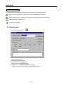
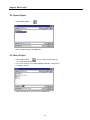
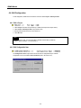
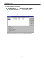
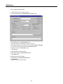
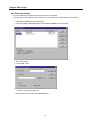
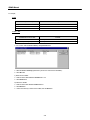
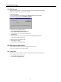
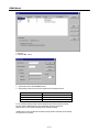
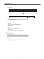
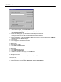
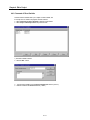
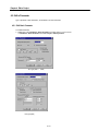
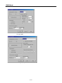
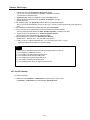
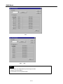
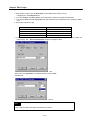
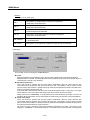
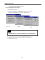
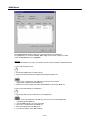
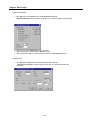
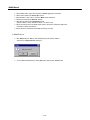
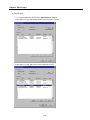
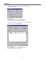
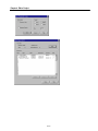
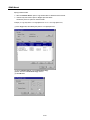
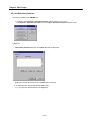
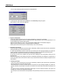
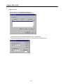
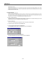
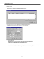
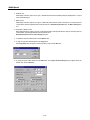
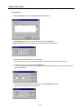
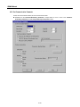
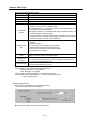
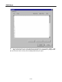
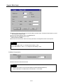
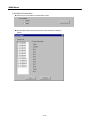
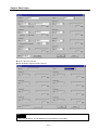
Chapter 4. Edit a Project
Chapter4 Edit a Project
Project is a basic element of GLOFA PLC. Basically, one project can be created for each PLC system. Project consists of
Configuration part, Parameter part and Included Library files. Configuration part is software part such as Global variables, Access
variables, Resource contents and etc.. Parameter part is a hardware part such as basic parameters, I/O parameters, link parameters
and etc. And Library files can be added or deleted in Included Library Files part.
Items
Project
Configuration
Configuration Global Variable
Access Variable
Resource
Resource Global Variable
Task Definition
Program Definition
Direct Variable Comment
Parameter
Basic Parameter
I/O Parameter
High Speed Link Parameter
Redundancy Parameter
Communication Parameter
Included library files
Descriptions
Define all the PLC systems
Set definition about PLC program
Variable which can be used in the configuration
Accessible variable list from other Configurations
CPU module
Variable which can be used in all resources within a project
Definition of program executive conditions
Definition of each program and it's executive conditions
Comment list using in direct variable
Defined content for the hardware in PLC system
Definition of basic hardware parameter
Described content on input/output module
Described content on high speed link parameters
Described content on input/output circuit and fault mask (for GMR only)
Described content on communication (for GM7 only)
File list for currently used libraries
4-1
GMWIN Manual
Reference: How to use folder
You can use the tree list to see briefly or detail tree list by clicking a mouse or pressing the right/left arrow key.
: Opened folder. If you click this folder, it changes into closed folder and lower branch is disappeared.
: Folder that can be opened. If you click this folder, it changes into opened folder and lower branch is appeared
: Unable to open folder (it describes an item).
: This folder means each item.
4.1. Create a Project
◆ Select Project - New Project (
).
◆ Enter the Project File Name.
◆ Select Base Type option radio button.
◆ Input the writer name in the Writer text box.
◆ Input the comment in the Comments text box.
◆ Click OK button. Then Define Program dialog box appears.
( Refer to the section 5.1 for more information of Define Program dialog box )
4-2
Chapter 4. Edit a Project
4.2. Open a Project
◆ Select Project - Open... (
).
◆ Select a desired project and click Open button.
4.3. Save a Project
◆ Select Project – Save(
). If you save already existing project file,
no message will be displayed.
◆ If you save a new file or save by selecting Project - Save As…, a dialog box will
be displayed as below.
◆ Enter the file name that you want to save and click Save button.
4-3
GMWIN Manual
4.4. Edit Configuration
To edit configuration, double-click on the each list of tree list or select Project - Edit Project Item.
4.4.1. Edit a Project
◆ Select Project in the lists of Project window( or double-click Project in the Project window )
◆ Select Project - Edit Project Item in the pull-down menu.
◆ Edit the project with the same way used in section 4.1.
◆ Click OK button.
Note
If you change PLC type, you must reload library (besides standard library) selectively.
(Refer to detail comment in "10.2 load Library ")
4.4.2. Edit Configuration Item
The Configuration Item in Project window shows the name of configuration that you selected.
Configuration name can be edited in Basic Parameters (refer to the section 4.5.1).
4-4
Chapter 4. Edit a Project
4.4.3. Edit a Configuration Global Variable
Configuration Global Variable can be used commonly for all programs in several resources.
So, it can be used only in GM1 that several resources can exist in.
◆ Select Configuration Globals in the Project window list.
◆ Select Project - Edit Project Item(or double-click the Configuration Globals in the Project window).
Description item in the above dialog box shows the content of the selected global variable in detail.
4-5
GMWIN Manual
1) Add a Configuration Global variable
◆ Click the Add... button in the above dialog box.
◆ Enter the Variable name in the Add/Edit Global Variables text box.
◆ Select Variable type in the Variable Kind list box.
◆ Select Data Type for Variable at list box or option radio button.
◆ Select Memory Allocation for Variable by option radio button in Memory Allocation.
◆ If you want to set an initial value, type it in the Initial Value text box.
◆ Enter the comment in the Comments text box.
◆ Click OK button.
2) Delete Configuration of Global Variable
◆ Select item to delete in the Global Variable List box .
◆ Click Delete button.
3) Edit Configuration of Global Variable
◆ Select item to edit in the Global Variable List box.
◆ Click Edit button.
◆ Enter the data in the same way to insert.
4-6
Chapter 4. Edit a Project
4.4.4. Edit Access Variable
An access variable is used to protect the data besides declared as access variable,
when other PLC(i.e. other configuration) read or write to it's own PLC, it allows you to constrain read/write access authority.
◆ Select Access Variable at the list in Project window.
◆ Select menu Project - Edit Project item(or double-click Access Variable in the Project window).
1) Insert Access Variable
◆ Click the Add.... button.
◆ Type the Variable Name in the Access Variable Name text box.
The name is available only Capital Letter.
◆ Select or enter the Access Path in the Access Path text box.
4-7
GMWIN Manual
For example,
In GM1
Available Input for Access path
Configuration Global Variable
Resource Global Variable
Direct Variable
Example
A, VALVE1
Resource Name. Global Variable name --> RES1.a
Resource Name. Direct Variable --> RES1. %10.0.0
In GM2~GM7
Available Input for Access path
Resource Global Variable
Direct Variable(excluding GM1)
Example
Use only Global variable name ---> A
Use only Direct Variable --> %10.0.0
◆ You can also select the Access Path by clicking Browse button.
◆ Select the Access Authority option button. (Choose one of the Read or Read/Write )
◆ Click OK button.
2) Delete Access Variable
◆ Select an item to delete in Access Variable List box.
◆ Click Delete button.
3) Edit Access Variable
◆ Select an item to edit in Access Variable List box.
◆ Click Edit button.
◆ Enter in the same way to insert access variable, and click OK button.
4-8
Chapter 4. Edit a Project
4.4.5. Edit Resource
Resource is a CPU for PLC. So, you can use maximum 4 resources in GM1 when you configure
a multi-CPU.(for others, only one resource is available.)
1) View Resource Name
You can see the Resource name defined by user at Resource item of the Project window.
You can edit a resource name in the "Edit Basic Parameter".
2) Add Resource (only available for GM1)
◆ Select Configuration in Project window.
◆ Select Project - Add Project Item - Resource .
◆ Enter a resource name in the Resource Name text box .
◆ Click OK button
◆ Now, new resource is added to the Project Window and Define Program dialog box
appears as like creating a new project.
3) Delete Resource (only available for GM1)
◆ Select Resource to delete.
◆ Select Project - Delete Project Item.
4.4.6. Edit Resource Global Variable
Resource Global Variable can be used for the all programs in the resource.
The process for editing is same as Global Variable.
4.4.7. Define Task
Task defines the executive condition of a program. Its types are single, Interval, interrupt and etc.
◆ Select Define Task in Project window.
◆ Select Project - Edit Project Item.
4-9
GMWIN Manual
1) Add Task
◆ Click the Add.... button.
◆ Type the task name in the Task Name text box.
◆ Enter following number for the executive condition in the Task Number text box.
Executive Condition
Interval
Interrupt
Single
Task Number
0 ~ 31
32 ~ 47 ( GM4, 5 : 32 ~ 39)
48 ~ 63
In case of interrupt, interrupt number and the designated task number is fixed automatically.
The task number of GM6 and GM7 is setup automatically under the priority order.
GM6 and GM7 can have 8 tasks including Interval, Interrupt and Single.
Variable name for single, duration time for interval and input position of interrupt card for interrupt
are represented as a number.
4-10
Chapter 4. Edit a Project
a) In case of Single
Boolean in the Resource Global Variable
Boolean in the Direct Variable
A, VALVE1, etc.
%1X0.0.0, %QX0.1.1, %MX10, etc.
b) In case of Interval
A constant for the duration time
T#10S, T#1H10M10S10MS, etc.
c) In case of Interrupt
Interrupt Number (GM1~3 : 0 ~15, GM4~7 : 0~7)
0, 1, 2 ... 15
◆ Select priority in the Priority list box. You can select priority number from 0 to 7,
and smaller number has higher priority.
◆ Click OK button.
2) Delete Task
◆ Select an item to delete in the Define Task list box.
◆ Click Delete button.
3) Edit Task
◆ Select an item to edit in the Define Task list box.
◆ Click Edit button.
◆ Enter in the same way to add a task, and click OK button.
4.4.8. Define a Program
The defined program in this process is the real program to be executed in PLC.
There are 2 kinds of program, one is scan program and the other is task-defined program.
When several scan programs exist, they execute the program in the defined order.
And the program defined as task is executed according to the condition of the task.
1) Add a Program
◆ Select Project - Add Project Item - Program in the pull down menu.
◆ And the dialog box appears as below.
4-11
GMWIN Manual
◆ Enter the instance(Program) name in Instance Name text box.
◆ Choose one between scan program(Single) and define task program(Task)
in the Execution Condition option.
◆ In case of task-defined program, you can enter the task name directly in the Task text box.
In other way, you can select one of the tasks already defined in the Task List dialog box
by clicking Browse button, and click OK button.
◆ Input the program name(~.SRC) in the Program File name text box. If there is a program already created, click Browse
button and select file in the Task List dialog box.
◆ Click OK button.
◆ Then new program is added into the Project window.
2) Delete Program
◆ Select a program to delete.
◆ Select Project - Delete Project Item.
3) Edit Program
◆ Select Program in Project window.
◆ Select Project - Edit Project Item.
◆ Edit data in the same way to add a program, and click OK button.
4) Change Program Order
◆ A program execution order is set as the order(from up to down) in the project tree list.
To change the order,
◆ Select a program item at the list in project window.
◆ Change order step by step using Project - UP(Program) or Project - Down(Program).
4-12
Chapter 4. Edit a Project
4.4.9. Comment of Direct Variable
Comment of Direct Variable allows you to explain on Direct Variable, and
it is exactly same as content in the program comments windows.
◆ Select Comments for Direct Variables at the list in Project window.
◆ Select Project - Edit Project item in the pull-down menu.
1) Add Direct Variable Comment
◆ Click the Add.... button.
◆ Type the Direct Variable name in the Direct Variable name text box (%I0.3.0).
◆ Enter the comment in the Comment text box.( LAMP1 ).
4-13
GMWIN Manual
◆ Click OK button.
2) Delete Comment for Direct Variables
◆ Select an item to delete in the Comment for Direct Variables list box.
◆ Click Delete button.
3) Edit the Comment for Direct Variable
◆ Select an item to edit in the Comment of Direct Variable list box.
◆ Click Edit button.
◆ Enter data in the same way to add a comment, and click OK button.
4-14
Chapter 4. Edit a Project
4.5. Edit a Parameter
Type of parameter : "Basic Parameter", "I/O Parameter" and "Link Parameter".
4.5.1. Edit Basic Parameter
To set Basic Parameter,
◆ Double-click on the "Parameters - Basic Parameters" in Project window, or move a cursor
to "Parameters - Basic Parameters" and Select "Project - Edit Project Item".
PLC type (GM2 ~ GM5)
PLC type (GM1)
4-15
GMWIN Manual
PLC type (GM6)
PLC type (GM7)
4-16
Chapter 4. Edit a Project
◆ Enter the PLC name in the "Configuration (PLC) Name" text box.
You can form PLC name with maximum 8 characters of alphabets and numbers.
And it becomes a configuration name.
◆ "Applied PLC Ver" shows you available PLC version in the GMWIN Version.
◆ Setup the permission of the remote access in "Remote Access Right" check box.
(Default : permission)
◆ Set Hot Restart option. If the "Hot Restart" option is checked, hot restart will be operated.
Then you must set the hot restart time, and you can set it from " 1 second" to "23 hour 59 minute 59 second" with second
scale.
◆ Set Cold Restart or Warm Restart by clicking option radio box in Restart Mode.
◆ Choose one mode of scan synchronization and scan synchronization in the GM1 Multi CPU
system by clicking option radio button in the "Multi- CPU Running Mode". (available for only GM1)
◆ Type the resource name in the text box of " Set Resource(CPU) Properties".
Resource name is formed with 8 characters of alphabet and digit.
◆ Set the watchdog time in the text box of "Watchdog Timer Duration".
Maximum time is "65535 ms" with "1 ms" scale. (GM7 : Max. 5000ms)
◆ In GM7, you can set ‘Software On/Off Delay Time’ and ‘Pulse Catch Input (%I0.0.x)’ in Input
property box. Please refer the GM7 user’s manual for details.
Note
1. Refer to the PLC User Manual about Remote Access Authority, Restart and %M area.
2. In case of GM1, it is available for resource 0 ~ 3.
3. In case of GM1, it has Multi-CPU Running setting mode.
4. In case of GM5, it has RS-422 speed setting mode.
5. In case of GM6, it has computer network setting mode.
6. In case of GM7, it has input property setting mode.
7. In case of GM6 and GM7, they do not support hot restart function.
4.5.2. Set I/O Parameter
To set the I/O Parameter,
◆ Double-click on the "Parameters - I/O Parameters" in Project window, or move a cursor
to "Parameters - I/O Parameters" and select "Project – Edit Project Item".
4-17
GMWIN Manual
GM1
GM2 ~ GM6
Note
In case of GM1, CPU configuration item (see above figure) is added.
(I/O type is set as DEF_EMPTY)
In case of GM7, it has no I/O parameter setting.
4-18
Chapter 4. Edit a Project
◆ Select the base number to set in the "Base Select", and the setting content of base you choose
is displayed in the "I/O configuration set".
◆ If you click "All Reset" in the "Base Select", then I/O parameters in all bases are changed into default value.
◆ If you click the "Reset" in the "I/O configuration set", then I/O parameter in the selected base slot is changed into default
value.
◆ Base setting range with PLC type
PLC type
GM1
GM2
GM3,4
GM6
Range
Base 0 ~ 31
Base 0 ~7
Base 0 ~ 3
Base 0 ~ 1
◆ If you want to set the I/O parameter of each slot, select the slot number in the "I/O configuration set" by clicking slot
number button. Then "Base Slot I/O Parameter" dialog box is displayed as below.
GM1
Select an item at the "Type Select", and select the number of I/O in the "Point".
Click OK button.
GM2~6
Note
In case of GM1, the option of CPU select and Redundancy are added.
4-19
GMWIN Manual
Reference
I/O type used as default value
I/O type
Content
DEF_I
When power is on, the input module in a selected slot is registered as
default value at the I/O refresh table.
DEF_O
When power is on, the output module in a selected slot is registered as
default value at the I/O refresh table.
DEF_IO
When power is on, the input/output module in a selected slot is registered
as default value at the I/O refresh table.
DEF_SP
When power is on, the special module in a selected slot is registered as
default value at the I/O refresh table.
DEF_MODULE
When power is on, the module in a selected slot is registered as default value
at the I/O refresh table.
DEF_EMPTY
When power is on, the selected slot is registered as empty slot at the I/O refresh table.
1) Base Setup
In case of GMR, you have to set a Base in the Base select box.
u Local A
Single input/output(I/O) can be installed only CPU A. And I/O module of digital content can be installed for Single I/O.
Setting each base as ‘Local A’ in the Base Selection box makes Single I/O and this system can be used for the part no
required backup to save the cost of redundancy.
u Redundancy Input/Output
CPU-A and CPU-B are operated using the same program simultaneously. When the system needs the data
synchronization during the operating, they synchronize data each other. If the operating is stop by disorder of master
CPU, the stand-by CPU maintain it’s operating continuously. At this time, the input/output connected to the master CPU in
base set as redundancy input/output gets OFF.
In this system, both of the master CPU and stand-by CPU control the input/output modules. For input data, you can apply
the data it had two or more same value in comparing the input values of Master, Stand-by and Transfer.
Setting up each base as ‘Redundancy’ in the Base Selection box makes Redundancy input/output. You have to set
both bases with the same number. And you set the transfer I/O location for the input comparison and the output feedback.
u Transfer Input/ Output
CPU-A and CPU-B are operated using the same program simultaneously. When the system needs the data
synchronization during the operating, they synchronize data each other. If the operating is stop by disorder of master
CPU, the stand-by CPU maintain it’s operating continuously. At this time, the input/output of each base set as transfer I/O
are continuously executed without any change of this status.
This system can call as a redundancy CPU because Redundancy input/output is not setting. This system is set by
setting up as ‘Transfer I/O’ in the parameter setting part. The stand-by CPU reads the information in the input/output
4-20
Chapter 4. Edit a Project
module periodically and check any fault of the connection.
4.5.3. Set the High Speed Link Parameter
To set the High Speed Link Parameter,
◆ Double-click on the "Parameters - Link Parameters" in Project window, or move a cursor
to "Parameters - Link Parameters" and select "Project - Edit Project Item".
GM1~ GM3
GM4, GM6
GM5
Note
The configuration for setting High Speed Link Parameter according to PLC type is like the above figure.
GM1/2/3 : High Speed Link 1 ~ 4 , GM4 / 6 : High Speed Link 1 ~ 2, GM5 : High Speed Link 1
If you click the High Speed Link Number button in the High Speed Link Parameter dialog box,
then "High Speed Link" dialog box will be displayed, which shows the list of registered item
and setting information of selected link.
4-21
GMWIN Manual
The "High Speed Link" dialog box allows you to setup the information of Link Setup and
each registered List. You can use the "Delete", "Edit", "Copy" and etc. button, or "Del" key to delete
an item and "Ctrl-V/Ctrl-C" key to "Copy/Paste".
Reference
Method of multi-selection has two ways, one is selection in order, the other is selection of scattered items in list.
1) How to select multi-items in order.
◆ Click the first registered item you wanted in the list.
◆ Drag a mouse to the final item in the desired list with pressing the left button of it.
◆ Move a cursor to registered list with "Tab" key, and move the cursor to the first
registered item in the desired list with "Arrow" key.
◆ Move the cursor to the final item in the desired list with "Arrow" key by pressing "Shift" key.
2) How to make a multi-selection for scattered items.
◆ By pressing "Ctrl" key, click mouse button on each registered item.
◆ Move a cursor to the registered list with "Tab" key, and move cursor to the first registered item
in the desired list with "Arrow" key.
◆ Press the "Shift + F8" key, and cursor start to blink.
◆ Move cursor to the desired item with "Arrow" key.
◆ Select each registered item with "Space" key.
◆ If you finish the selection, Press "Shift + F8" key.
4-22
Chapter 4. Edit a Project
1) Set Link Information
◆ Click "Edit" button at the "Link Set" area in the "High Speed Link Set" then
"High Speed1Link Set" dialog box appears, which allows you to setup the information for the link setting.
◆ Select a network type in "Network Type" option radio button.
◆ Select the slot number of the link module in "Slot Num" List box.
◆ Select the self station number to save the High Link Parameter in the "Self-Stat Num" text box.
2) Set Entry List
◆ Click "Edit" button at Entry List box after selecting registered list number, then
" High Speed Link Item Edit " dialog box appears, which allow you to setup the information of the
entry link list.
4-23
GMWIN Manual
◆ Select whether Station Type is local or remote in "Station Type" option radio button.
◆ Set the station number in the "Station No" text box.
◆ Select whether it is data to send or receive in "Mode" option radio button.
◆ Set the block number in the "Block No" text box.
◆ Select the send period in the "Send Period" list box.
(A:20ms, B:50ms, C:100ms, D:200ms, E:500ms, F:1S, G:5S, H:10S)
◆ Set the send/receive area in the "Area" option radio box. Each area is selected by option button
and address is fixed in each text box.
◆ Set the data size to communicate in the "Size" text box.(by word size)
3) Delete Entry List
◆ Click "Delete" button or "Del" key, after selecting the entry list number to delete at
entry list box in "High Speed Link" dialog box.
◆ You can delete the selected item by clicking "OK" button, otherwise click "Cancel" button.
4-24
Chapter 4. Edit a Project
4) Copy Entry List
◆ To copy the list within Entry List each other in "High Speed Link" dialog box,
(1) Press "Ctrl - C" to copy, after selecting the item to copy using a cursor or mouse.
(2) Press "Ctrl - V" to paste, after moving a cursor to the location you want.
4-25
GMWIN Manual
◆ Click "Copy" button, after selecting the entry item number at the entry list box in the
"High Speed Link" dialog box.
A) Copy Between Links
◆ Select "Between Links " option to copy a selected list to other link.
◆ Select the Link number to paste in "Target" option radio button.
Example) To copy the entry list 0.1.2.3 in High Speed Link 1 to 0.1.2.3 in High Speed Link 2,
(1) Select the entry list 0.1.2 in the "High Speed Link 1".
(2) Click "Copy" button
(3) Choose the "Between Links " in "Link Parameter Copy" dialog box
(4) Select "Link 2" in "Target" box and click OK button.
4-26
Chapter 4. Edit a Project
4-27
GMWIN Manual
B) Copy Between Entries
◆ Select the "Between Entries" option to copy selected entries to other link list in the same link.
◆ Enter the entry Item number to paste in "Target" option radio button.
selected entry Items are copied from selected number.
Example) To copy entry Items 0.1.2 in High Speed Link 1 to 10.11.12 in High Speed Link 1,
(1) Click "Copy" button, after selecting entry Items 0.1.2 in High Speed Link 1.
(2) Choose "Between Entries" at the "Link Parameter Copy"
(3) Enter "10" in the "Link Parameter Copy" text box.
(4) Click OK button.
4-28
Chapter 4. Edit a Project
4.5.4. Set Redundancy Parameter
This function is available only for GM1RED PLC.
◆ Double-click on the Parameter - Redundancy Parameter in Project window or move a cursor
on the Parameter - Redundancy Parameter and choose Project - Edit Project properties in pull-down menu.
1) Base Set
At Redundancy Parameter dialog box, click the Base Set… button for setting base.
Double-click on the item that you want to set or click Edit button to set the base.
◆ To delete entry items, select the items and click Delete… button.
◆ To copy entry items, select the items and click Copy button.
4-29
GMWIN Manual
You can copy by entering the position of the base and clicking OK button.
◆ To edit entry items, select the items and click Edit button. Then Redundancy dialog box appears.
Select the item you want to edit and click OK button.
◆ Single Input/Output(I/O)
Local A and Local B are operated by the same program simultaneously, and the data is synchronized
by transferring inputted data from Local A to Local B. When system stops operating by Local A disorder, input/output of Local
A stops operating and all connected outputs get OFF.
Single I/O can be installed only in Local A. And only I/O modules of digital contacts can be installed for Single I/O.
Single I/O is made by setting each base as 'Single input/output' in the setting part.
And this system can be used for the part not to require backup to save cost for redundancy
◆ Redundancy Input/Output
Local A and Local B are operated by the same program simultaneously. When the system needs the data synchronization
during the operating, they synchronize data each other.
If a system stops operating by disorder of master CPU, the stand-by CPU starts operating immediately and continues its
operating. At this time, the input/outputs connected to the master CPU in bases set as redundancy input/output get OFF.
In this system, both of master CPU and stand-by CPU control the input/output modules.
For input data, the data can be adapted as the input data after comparing the data among Master, Stand-by and the
transferred value.
Redundancy input/output is set by setting up each base as 'Redundancy input/output' in the setting part. And both bases of
Local A and Local B must be set as the same number. And you set the transfer I/O location for the input comparison and the
output feedback.
◆ Transfer input/output
Local A and Local B are operated by the same program simultaneously. When the system needs the data synchronization
during the operating, they synchronize data each other.
If the master CPU is out of order, the system stops and the stand-by CPU starts operating immediately and continues its
operating. At this time, the input/outputs of each base set as transfer I/O are continuously executed without any change of the
status.
This system can call as a redundancy CPU because an input/output is not for the redundant mechanism. This system is set
by setting up as "Transfer I/O" in the parameter setting part.
The stand-by CPU reads the information in the input/output module periodically and checks any fault of the connection all the
time.
4-30
Chapter 4. Edit a Project
2) Input Circuit Set
The below dialog box is for setting triple redundancy input.
Click Circuit Set button in the Redundancy Parameter dialog box.
If you double-click the item in the Input Circuit Set dialog box, or click Edit button,
the Input Circuit Set dialog box appears. It allows you to set input circuit for the appropriate item.
4-31
GMWIN Manual
Triple redundancy input
Triple redundancy input allows you to use that data as input value of the program after selecting identified 2 data of 3 data
compared to the inputted data. So, you must have 2 input modules mounted on the same redundancy base slot and 1 input
module mounted on the transfer base.
To set the Input Circuit Item,
◆ Position of Redundancy Base Input
Indicates the position and channel of input module mounted on a redundancy base for the triple redundancy input. There is
only one item for fixing a position because input module of both Local A and B must be on the same base slot. And the
designated base must the base set as Redundancy I/O in the Base Set dialog box.
◆ Position of Transfer Base Input
Indicates the position and channel of input module mounted on a transfer base for the triple redundancy input. And the
designated base must be set as Transfer I/O in the Base Set dialog box.
◆ Setting Time Observation
It is time value for allowing temporary disagreement of input value by delay of the input module.
◆ To delete the entry item, select the item and click Delete button.
◆ To copy the entry item, select the item and click Copy button.
Then Copy Entry dialog box appears. Enter the position to copy, and click OK button.
◆ To edit the entry item, select the item and click Edit button.
Then Input Circuit Set dialog box appears. Enter the data and click OK button.
4-32
Chapter 4. Edit a Project
3) Output Circuit Set
Click the output circuit setting button in Redundancy Parameter dialog box.
Double-click on the item to set or click on Edit button in the Output Circuit Set dialog box.
Then Output Circuit Set dialog box appears. It allows you to set the selected item.
◆ Position of Output Word
Indicates the position and channel of redundancy output module. At this time the designated base
must be the base set as Redundancy I/O in the Base Setting dialog box.
◆ Location of Feedback Input Word
When setting redundancy output as O-F type, it indicates the position and channel of feedback input module. At this time, the
designated base must be the base set as Redundancy/Translate I/O in the Base Setting dialog box.
4-33
GMWIN Manual
◆ Feedback Time
When setting redundancy output as O-F type, it indicates the time interval for admitting temporary disagreement of a output
value and feedback input.
◆ Master control
When setting redundancy output as O-F type, it indicates the position and the number of the output to cut off the power and
contact number. And the designated base must be the base set as Redundancy/Transfer I/O in the Base Setting dialog
box.
◆ Observation of Master control
When setting redundancy output as O-F type, it indicates the position of the input that observe output to cut off the power and
contact number. And the designated base must be the base set as
Redundancy/Transfer I/O in the Base Setting dialog box.
◆ To delete the entry item, select the item and click Delete button.
◆ To copy the entry item, select the item and click Copy button.
Then Copy Entry dialog box appears. Enter the position to copy and click OK button.
◆ To edit the entry item, select the item and click Edit button. Then Output Circuit Setting dialog box appears. Enter the
desired value, and click OK button.
4-34
Chapter 4. Edit a Project
4) Fault Mask Set
Click the Fault Mask set… button in the Redundancy Parameter dialog box.
In Fault Mask Set dialog box, if you double-click on the item to set or click Edit button,
Fault Mask Set dialog box appears, which helps to set the input circuit for the appropriate item.
◆ The Position of module to be continued in case of disorder
When a machine is out of order, you can select the position of module to be continued at any base setting status.
◆ To delete the entry items, select the item and click Delete button.
◆ To copy the entry items, select the item and click Copy button. Then Copy Entry dialog box appears. Enter the position to
copy and click OK button.
◆ To edit the entry items, select the item and click Edit button. Then Fault Mask Set dialog box
appears. Enter the desired value and click OK button.
4-35
GMWIN Manual
4.5.5. Set Communication Parameter
In GM7, select Communication Method, Protocol and Transmission Mode.
u Double-click on the Parameter-Redundancy Parameter in Project window or move a cursor to the ParameterRedundancy Parameter and select Project-Edit Project Properties in Menu.
4-36
Chapter 4. Edit a Project
u Set the Communication Method as follows.
Item
Contents
Self Station No.
0-31 are selectable. (* Note 1)
Baud Rate
You can set 1200, 2400, 4800, 9600, 19200, 38400, 57600 bps.
Data Bit
You can set 7 or 8 Bits. ( *Note 2)
Parity Bit
You can set None, Even and Odd.
Stop Bit
You can set 1 or 2 Bit(s) (* Note 3)
• RS232C Null Modem or RS422/485 : Select it to communicate with the internal function
of GM7’s basic unit or Cnet I/F module(G7L-CUEC).
• RS232C Dedicated Line : On communication with Cnet I/F module(G7L-CUEB), if you
use a Dedicated Line, select this channel.
Communication
• RS232C Dial Up Modem : On communication with Cnet I/F module(G7L-CUEB), if you
Channel
use the Dial Up Modem, select this channel.
Note) A Communication of RS232C Dedicated Modem or RS232C Dial Up Modem is
available at the Cnet I/F module(G7L-CUEB) supports RS232C only and no available
at the Cnet I/F module (G7L-CUEC) supports RS422/485.
• It is a waiting time of an answer frame after transmitting required frame in the GM7 is set
as Master.
• Default value is 500ms.
Timeout in Master • You have to set it under the consideration of the maximum
Mode
period of Master PLC transmission and receiving(Tx/Rx).
• If you set the less value than the maximum period of Master
PLC transmission and receiving.
Master
/ Slave
Read Status of
Slave PLC
Transmission Mode
If you set the Master, it become the subject in the communication system and it allows
reading and writing the data in the selected device(PLC).
Set it to read the Status of GM 7 basic unit is designated as Slave.
Do no select it except monitoring the status of slave. It can reduce communication speed.
(You can set it in the dedicated protocol only)
ASC II or RTU Mode is selectable.
(You can set it in the Modbus Protocol only)
*Note 1) In Modbus, do not set the broadcast station number with ‘0’.
It is became one factor of a wrong operation.
In GM7, Broadcast is not supported.
*Note 2) In Modbus, set 7Bits in the ASC II box and set 8 Bits in the RTU mode.
*Note 3) In Modbus, please set the Stop Bit as ‘1’ when you set the Parity Bit, and set
‘2’ if you not set the Parity Bit.
1) Private Communication
u Set the Protocol as Dedicated Line, and select Master or Slave.
If you selected Master, Entry List button appears.
u Click the Entry List button, then Private 1 dialog box appears.
4-37
GMWIN Manual
The above dialog box allows you to set the information of each registered List. You can use the “Delete’, ‘Edit’,
‘Copy’ and etc. button, or ‘Del’ key to delete the multi-selected items and ‘Ctrl-V/Ctrl-C’ key to Copy and Edit.
u Click the desired number in the Entry List then the Entry List Set dialog box appears.
u
4-38
Chapter 4. Edit a Project
u Select the Send button in Mode when you want Data writing to the Slave station, and select the Receive button if you want
Data reading from the Slave station.
u Set the Slave Number(Opposite station) in the Station No.box.
u Set the data size in the Size(Word) box in word.
Max. 60 words are available.
u Set Tx/Rx area in the Area box. Select each area by option button, and designate the address in each input box.
Note
1.If you select %MW0 : Enter ‘0’ in the input box after selecting ‘%MW’.
2.If you select %QW0.1.0 : Enter ‘0.1.0’ in the input box after selecting ‘%QW’.
2) Modbus Communication
u Set the Protocol with Modbus, and select Master or Slave.
u Select ASCII in the Transmission Mode box.
Note
1. Modbus communication use the function block(MOD0102,MOD0203,MOD0506,MOD1516).
Refer to GM7 Manual ‘8.3 Modbus Protocol Communication’ for more details.
4-39
GMWIN Manual
3) User Defined Communication
u Set the Protocol as User Defined, and select Master or Slave.
u Click the desired number in the Frame List then the Frame Information Set dialog box
appears.
4-40
Chapter 4. Edit a Project
u Set Tx or Rx in the Tx/Rx box.
u Enter the Header, Segment and Tail in each box.
Note
Refer to the GM7 Manual “8.2 User Defined Protocol Communication for more details.
4-41