1
User’s Manual
LG Programmable Logic Controller
Cnet I/F Module
GLOFA-GM
G3L-CUEA
G4L-CUEA
G6L-CUEB
G6L-CUEC
G7L-CUEB
G7L-CUEC
LG INDUSTRIAL SYSTEMS
This user’s manual describes functions of Cnet I/F module.
Please read this manual carefully to understand the functions thoroughly prior to system design.
Revision record
Revision record
1st edition
1st revision
Date of issue revised
Contents revised
1 print
- GM7 Cnet I/F module added
- Functions of frame editor Version 2.0 added
st
2000.01.10
Contents
Chapter 1 Introduction žžžžžžžžžžžžžžžžžžžžžžžžžžžžžžžžžžžžžžžžžžžžžžžžžžžžžžžžžžžžžžžžžžžžžžžžžžžžžžžžžžžžžžž 1-1~1-7
1.1 Module selection per CPU type žžžžžžžžžžžžžžžžžžžžžžžžžžžžžžžžžžžžžžžžžžžžžžžžžžžžžžžžžžžžžžžžžžžžžžžžžž 1-2
1.2 Functions of Version 2.0 žžžžžžžžžžžžžžžžžžžžžžžžžžžžžžžžž žžžžžžžžžžžžžžžžžžžžžžžžžžžžžžžžžžžžžžžžžžžžžžž 1-3
1.2.1 Version check žžžžžžžžžžžžžžžžžžžžžžžžžžžžžžžžžžžžžžžžžžžžžžžžžžžžžžžžžžžžžžžžžžžžžžžžžžžžžžžžžžžžžžžžžžž 1-3
1.2.2 Added functions introduction of Version 2.0žžžžžžžžžžžžžžžžžžžžžžžžžžžžžžžžžžžžžžžžžžžžžžžžžžžžžžžžžž 1-6
1.2.3 Established functions žžžžžžžžžžžžžžžžžžžžžžžžžžžžžžžžžžžžžžžžžžžžžžžžžžžžžžžžžžžžžžžžžžžžžžžžžžžžžžžžžž 1-7
1.2.4 Frame editor Version 2.0 žžžžžžžžžžžžžžžžžžžžžžžžžžžžžžžžžžžžžžžžžžžžžžžžžžžžžžžžžžžžžžžžžžžžžžžžžžžž 1-7
1.2.5 Added function of Version 2.0 žžžžžžžžžžžžžžžžžžžžžžžžžžžžžžžžžžžžžžžžžžžžžžžžžžžžžžžžžžžžžžžžžžžžžžžž 1-7
Chapter 2 Definition of termsžžžžžžžžžžžžžžžžžžžžžžžžžžžžžžžžžžžžžžžžžžžžžžžžžžžžžžžžžžžžžžžžžžžžžžžžžžžžžžž 2-1~2-6
Chapter 3 Product specification žžžžžžžžžžžžžžžžžžžžžžžžžžžžžžžžžžžžžžžžžžžžžžžžžžžžžžžžžžžžžžžžžžžžžžžžžž 3-1~3-12
3.1 General specification žžžžžžžžžžžžžžžžžžžžžžžžžžžžžžžžžžžžžžžžžžž žžžžžžžžžžžžžžžžžžžžžžžžžžžžžžžžžžžžžžžžž 3-1
3.2 Performance specifications žžžžžžžžžžžžžžžžžžžžžžžžžžžžžžžžžžžžžžžžžžžžžžžžžžžžžžžžžžžžžžžžžžžžžžžžžžžž 3-2
3.3 Cable specifications žžžžžžžžžžžžžžžžžžžžžžžžžžžžžžžžžžžžžžžžžžžžžžžžžžžžžžžžžžžžžžžžžžžžžžžžžžžžžžžžžžžžžž 3-4
3.4 Terminating resistance žžžžžžžžžžžžžžžžžžžžžžžžžžžžžžžžžžžžžžžžžžžžžžžžžžžžžžžžžžžžžžžžžžžžžžžžžžžžžžžžžž 3-5
3.5 Structure žžžžžžžžžžžžžžžžžžžžžžžžžžžžžžžžžžžžžžžžžžžžžžžžžžžžžžžžžžžžžžžžžžžžžžžžžžžžžžžžžžžžžžžžžžžžžžžžžž 3-7
3.5.1 Part names of G3L-CUEA žžžžžžžžžžžžžžžžžžžžžžžžžžžžžžžžžžžžžžžžžžžžžžžžžžžžžžžžžžžžžžžžžžžžžžžžžžžžžž 3-7
3.5.2 Part names of G4L-CUEA žžžžžžžžžžžžžžžžžžžžž žžžžžžžžžžžžžžžžžžžžžžžžžž žžžžžžžžž žžžžžžžžžžžžžžžžžžžžžž 3-8
3.5.3 Part names of G6L-CUEB žžžžžžžžžžžžžžžžžžžžžžžžžžžžžžžžžžžžž žžžžžžžžžžžžžžžžžž žžžžžžžžžžžžžžžžžžžžžžž 3-9
3.5.4 Part names of G6L-CUEC žžžžžžžžžžžžžžžžžžžžžžžžžžžžžžžžžžžžžžžžžžžžž žžžžžžžž žžžžžžžžžžžžžžžžžžžžžžž 3-10
3.5.5 Part names of G7L-CUEB žžžžžžžžžžžžžžžžžžžžžžžžžžžžžžžžžžžžžžž žžžžžžž žžžžžžžžžžžžžžžžžžžžžžžžžžžžžž 3-11
3.5.6 Part names of G7L-CUEC žžžžžžžžžžžžžžžžžžžžžž žžžžžžžžžžžžžžžžžžž žžžžžžžžžžžžžžžžžžžžžžžžžžžžžžžžžžž 3-12
Chapter 4 Performance specification žžžžžžžžžžžžžžžžžžžžžžžžžžžžžžžžžžžžžžžžžžžžžžžžžžžžžžžžžžžžžžžžžžžž 4-1~4-33
4.1 Operating mode setting žžžžžžžžžžžžžžžžžžžžžžžžžžžžžžžžžžžžžžžžžžžžžžžžžžžžžžžžžžžžžžžžžžžžžžžžžžžžžžžžžž 4-1
4.1.1 Channel operation in interlocking mode žžžžžžžžžžžžžžžžžžžžžžžžžžžžžžžžžžžžžžžžžžžžžžžžžžžžžžžžžžžžžžž 4-3
4.1.2 Channel operation in stand-alone mode žžžžžžžžžžžžžžžžžžžžžžžžžžžžžžžžžžžžžžžžžžžžžžžžžžžžžžžžžžžžžžž 4-4
4.1.3 Channel operation in self diagnosis mode (Loop Back) žžžžžžžžžžžžžžžžžžžžžžžžžžžžžžžžžžžžžžžžžžžžž 4-5
4.2 Method of serial interfacežžžžžžžžžžžžžžžžžžžžžžžžžžžžžžžžžžžžžžžžžžžžžžžžžžžžžžžžžžžžžžžžžžžžžžžžžžžžžžž 4-6
4.2.1 RS-232C interface žžžžžžžžžžžžžžžžžžžžžžžžžžžžžžžžžžžžžžžžžžžžžžžžžžžžžžžžžžžžžžžžžžžžžžžžžžžžžžžžžžž 4-6
4.2.2 RS-422 interface žžžžžžžžžžžžžžžžžžžžžžžžžžžžžžžžžžžžžžžžžžžžžžžžžžžžžžžžžžžžžžžžžžžžžžžžžžžžžžžžžžžžžžžž 4-9
4.3 How to set transmission specifications žžžžžžžžžžžžžžžžžžžžžžžžžžžžžžžžžžžžžžžžžžžžžžžžžžžžžžžžžžžžžžžžžž 4-11
4.3.1 Setting items žžžžžžžžžžžžžžžžžžžžžžžžžžžžžžžžžžžžžžžžžžžžžžžžžžžžžžžžžžžžžžžžžžžžžžžžžžžžžžžžžžžžžžžžžžž 4-11
4.3.2 How to set žžžžžžžžžžžžžžžžžžžžžžžžžžžžžžžžžžžžžžžžžžžžžžžžžžžžžžžžžžžžžžžžžžžžžžžžžžžžžžžžžžžžžžžžžžžžž 4-12
4.3.3 Reading setting values žžžžžžžžžžžžžžžžžžžžžžžžžžžžžžžžžžžžžžžžžžžžžžžžžžžžžžžžžžžžžžžžžžžžžžžžžžžžžžž 4-16
4.3.4 Transmission specification setting of Gm7 series žžžžžžžžžžžžžžžžžžžžžžžžžžžžžžžžžžžžžžžžžžžžžžžžžžž 4-17
4.4 How to connect to modem žžžžžžžžžžžžžžžžžžžžžžžžžžžžžžžžžžžžžžžžžžžžžžžžžžžžžžžžžžžžžžžžžžžžžžžžžžžžžž 4-19
4.4.1 Connection to dedicated modem (RS-232C) žžžžžžžžžžžžžžžžžžžžžžžž žžžžžžžžžžžžžžžžžžžžžžžžžžžžžžžž 4-20
4.4.2 Connection to dial-up modem (RS-232C) žžžžžžžžžžžžžžžžžžžžžžžžžžžžžžžžžžžžžžžžžžžžžžžžžžžžžžžžžžž 4-27
Chapter 5 Frame Editor žžžžžžžžžžžžžžžžžžžžžžžžžžžžžžžžžžžžžžžžžžžžžžžžžžžžžžžžžžžžžžžžžžžžžžžžžžžžžžžžžžžž 5-1~5-43
5.1 Basic functions žžžžžžžžžžžžžžžžžžžžžžžžžžžžžžžžžžžžžžžžžžžžžžžžžžžžžžžžžžžžžžžžžžžžžžžžžžžžžžžžžžžžžžžžžžž 5-1
5.2 Screen configuration and menu žžžžžžžžžžžžžžžžžžžžžžžžžžžžžžžžžžžžžžžžžžžžžžžžžžžžžžžžžžžžžžžžžžžžžžžžž 5-2
5.2.1 Basic parameter setting žžžžžžžžžžžžžžžžžžžžžžžžžžžžžžžžžžžžž žžžžžžž žžžžžžžžžžžžžžžžžžžžžžžžžžžžžžžžžžžž 5-6
5.2.2 Frame setting žžžžžžžžžžžžžžžžžžžžžžžžžžžžžžžžžžžžžžžžžžžžžžžžžžžžžžžžžžžžžžžžžžžžžžžžžžžžžžžžžžžžžžžžžž 5-7
5.2.3 Frame writing/reading žžžžžžžžžžžžžžžžžžžžžžžžžžžžžžžžžžžžžžžžžžžžžžžžžžžžžžžžžžžžžžžžžžžžžžžžžžžžžžžž 5-23
5.2.4 Monitor function žžžžžžžžžžžžžžžžžžžžžžžžžžžžžžžžžžžžžžžžžžžžžžžžžžžžžžžžžžžžžžžžžžžžžžžžžžžžžžžžžžžžžž 5-27
5.3 Managing function of flash memory žžžžžžžžžžžžžžžžžžžžžžžžžžžžžžžžžžžžžžžžžžžžžžžžžžžžžžžžžžžžžžžžžžžž 5-31
5.3.1 Writing of flash memory žžžžžžžžžžžžžžžžžžžžžžžžžžžžžžžžžžžžžžžžžžžžžžžžžžžžžžžžžžžžžžžžžžžžžžžžžžžžžžž 5-31
5.3.2 Reading of flash memory žžžžžžžžžžžžžžžžžžžžžžžžžžžžžžžžžžžžžžžžžžžžžžžžžžžžžžžžžžžžžžžžžžžžžžžžžžžžž 5-34
5.4 Changing of online mode žžžžžžžžžžžžžžžžžžžžžžžžžžžžžžžžžžžžžžžžžžžžžžžžžžžžžžžžžžžžžžžžžžžžžžžžžžžžžž 5-35
5.4.1 Changing of local operating mode žžžžžžžžžžžžžžžžžžžžžžžžžžžž žžžžžžžžžžžžžžžžžžžžžžžžžžžžžžžžžžžžžžž 5-35
5.4.2 Changing of remote operating mode žžžžžžžžžžžžžžžžžžžžžžžžžžžžžžžžžžžžžžžžžžžžžžžžžžžžžžžžžžžžžžžžž 5-39
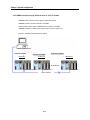
Chapter 6 System configuration žžžžžžžžžžžžžžžžžžžžžžžžžžžžžžžžžžžžžžžžžžžžžžžžžžžžžžžžžžžžžžžžžžžžžžžžžž 6-1~6-11
6.1 System configuration availabležžžžžžžžžžžžžžžžžžžžžžžžžžžžžžžžžžžžžžžžžžžžžžžžžžžžžžžžžžžžžžžžžžžžžžžžžž 6-1
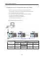
6.1.1 1:1 connection (no modem) to PC žžžžžžžžžžžžžžžžžžžžžžžžžžžžžžžžžžžžžžžžžžžžžžžžžžžžžžžžžžžžžžžžžžž 6-1
6.1.2 1:1 dedicated modem connection to PC žžžžžžžžžžžžžžžžžžžžžžžžžžžžžžžžžžžžžžžžžžžžžžžžžžžžžžžžžžžžž 6-2
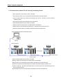
6.1.3 Modem connection to PC & communication between Cnet I/F modulesžžžžžžžžžžžžžžžžžžžžžžžžžžž 6-3
6.1.4 Communication between PC and Cnet using interlocking channelžžžžžžžžžžžžžžžžžžžžžžžžžžžžžžžžž 6-4
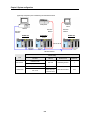
6.1.5 Interlocking & stand-alone channel communicationžžžžžžžžžžžžžžžžžžžžžžžžžžžžžžžžžžžžžžžžžžžžžžžžž 6-5
6.1.6 Dedicated communication to PC & other company’s RS-422 communication žžžžžžžžžžžžžžžžžžžžž 6-6
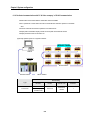
6.1.7 Optical modem communication for mobile communicationžžžžžžžžžžžžžžžžžžžžžžžžžžžžžžžžžžžžžžžžžž 6-7
6.1.8 Wireless modem communication between revolution bodies žžžžžžžžžžžžžžžžžžžžžžžžžžžžžžžžžžžžžžž 6-8
6.1.9 TM/TC communication system žžžžžžžžžžžžžžžžžžžžžžžžžžžžžžžžžžžžžžžžžžžžžžžžžžžžžžžžžžžžžžžžžžžžžž 6-9
6.2 System configuration unavailable žžžžžžžžžžžžžžžžžžžžžžžžžžžžžžžžžžžžžžžžžžžžžžžžžžžžžžžžžžžžžžžžžžžžž 6-10
6.2.1 Dial-up modem communication between Cnet I/F modulesžžžžžžžžžžžžžžžžžžžžžžžžžžžžžžžžžžžžžžž 6-10
6.2.2 GMWIN connection using RS-422 channel of Cnet I/F module žžžžžžžžžžžžžžžžžžžžžžžžžžžžžžžžžžž 6-11
Chapter 7 Communication program žžžžžžžžžžžžžžžžžžžžžžžžžžžžžžžžžžžžžžžžžžžžžžžžžžžžžžžžžžžžžžžžžžž 7-1~7-132
7.1 User defined communication žžžžžžžžžžžžžžžžžžžžžžžžžžžžžžžžžžžžžžžžžžžžžžžžžžžžžžžžžžžžžžžžžžžžžžžžžžž 7-1
7.1.1 Introduction žžžžžžžžžžžžžžžžžžžžžžžžžžžžžžžžžžžžžžžžžžžžžžžžžžžžžžžžžžžžžžžžžžžžžžžžžžžžžžžžžžžžžžžžžžžž 7-1
7.1.2 User defined operation žžžžžžžžžžžžžžžžžžžžžžžžžžžžžžžžžžžžžžžžžžžžžžžžžžžžžžžžžžžžžžžžžžžžžžžžžžžžžžžž 7-2
7.1.3 User defined Function Block (SND_MSG ,RCV_MSG) žžžžžžžžžžžžžžžžžžžžžžžžžžžžžžžžžžžžžžžžžžžžžž 7-5
7.1.4 Example of user defined programming žžžžžžžžžžžžžžžžžžžžžžžžžžžžžžžžžžžžžžžžžžžžžžžžžžžžžžžžžžžžž 7-12
7.1.5 User defined communication for Gm7 series žžžžžžžžžžžžžžžžžžžžžžžžžžžžžžžžžžžžžžžžžžžžžžžžžžžžžž 7-25
7.2 Dedicated communication slave žžžžžžžžžžžžžžžžžžžžžžžžžžžžžžžžžžžžžžžžžžžžžžžžžžžžžžžžžžžžžžžžžžžžžž 7-34
7.2.1 Introduction žžžžžžžžžžžžžžžžžžžžžžžžžžžžžžžžžžžžžžžžžžžžžžžžžžžžžžžžžžžžžžžžžžžžžžžžžžžžžžžžžžžžžžžžž 7-34
7.2.2 Frame structure žžžžžžžžžžžžžžžžžžžžžžžžžžžžžžžžžžžžžžžžžžžžžžžžžžžžžžžžžžžžžžžžžžžžžžžžžžžžžžžžžžžžžž 7-35
7.2.3 List of commands žžžžžžžžžžžžžžžžžžžžžžžžžžžžžžžžžžžžžžžžžžžžžžžžžžžžžžžžžžžžžžžžžžžžžžžžžžžžžžžžžžžž 7-38
7.2.4 Data type žžžžžžžžžžžžžžžžžžžžžžžžžžžžžžžžžžžžžžžžžžžžžžžžžžžžžžžžžžžžžžžžžžžžžžžžžžžžžžžžžžžžžžžžžžžžž 7-40
7.2.5 Execution of commands (Ex.) žžžžžžžžžžžžžžžžžžžžžžžžžžžžžžžžžžžžžžžžžžžžžžžžžžžžžžž žžžžžžžžžžžžžžžž 7-42
7.3 Dedicated communication master (communication between Cnets)žžžžžžžžžžžžžžžžžžžžžžžžžžžžžžžž 7-94
7.3.1 Introduction žžžžžžžžžžžžžžžžžžžžžžžžžžžžžžžžžžžžžžžžžžžžžžžžžžžžžžžžžžžžžžžžžžžžžžžžžžžžžžžžžžžžžžžžžž 7-94
7.3.2 Function Block for dedicated communicationžžžžžžžžžžžžžžžžžžžžžžžžžžžžžžžžžžžžžžžžžžžžžžžžžžžžžž 7-95
7.3.3 How to use dedicated Function Blockžžžžžžžžžžžžžžžžžžžžžžžžžžžžžžžžžžžžžžžžžžžžžžžžžžžžžžžžžžžžžžž 7-97
7.3.4 Dedicated communication master for G7L-CUECžžžžžžžžžžžžžžžžžžžžžžžžžžžžžžžžžžžžžžžžžžžžžžžž 7-102
7.4 Other company’s dedicated mode žžžžžžžžžžžžžžžžžžžžžžžžžžžžžžžžžžžžžžžžžžžžžžžžžžžžžžžžžžžžžžžžžž 7-109
7.4.1 Introduction žžžžžžžžžžžžžžžžžžžžžžžžžžžžžžžžžžžžžžžžžžžžžžžžžžžžžžžžžžžžžžžžžžžžžžžžžžžžžžžžžžžžžžžžž 7-109
7.4.2 Operating mode & downloading of communication driver žžžžžžžžžžžžžžžžžžžžžžžžžžžžžžžžžžžžžžžž 7-110
7.4.3 Specifications of A. B communication driver žžžžžžžžžžžžžžžžžžžžžžžžžžžžžžžžžžžžžžžžžžžžžžžžžžžžžž 7-114
7.4.4 Specifications of MODBUS communication driver žžžžžžžžžžžžžžžžžžžžžžžžžžžžžžžžžžžžžžžžžžžžžžž 7-119
7.5 GMWIN remote connection žžžžžžžžžžžžžžžžžžžžžžžžžžžžžžžžžžžžžžžžžžžžžžžžžžžžžžžžžžžžžžžžžžžžžžžžžž 7-122
7.5.1 Introduction žžžžžžžžžžžžžžžžžžžžžžžžžžžžžžžžžžžžžžžžžžžžžžžžžžžžžžžžžžžžžžžžžžžžžžžžžžžžžžžžžžžžžžžžž 7-122
7.5.2 GMWIN remote connection žžžžžžžžžžžžžžžžžžžžžžžžžžžžžžžžžžžžžžžžžžžžžžžžžžžžžžžžžžžžžžžžžžžžžžžž 7-122
7.5.3 Remote connection between Cnet I/F modulesžžžžžžžžžžžžžžžžžžžžžžžžžžžžžžžžžžžžžžžžžžžžžžžžžž 7-129
Chapter 8 Exercising program žžžžžžžžžžžžžžžžžžžžžžžžžžžžžžžžžžžžžžžžžžžžžžžžžžžžžžžžžžžžžžžžžžžžžžžžžžžž 8-1~8-66
8.1 TM ( Tele Metering) system using dedicated modemžžžžžžžžžžžžžžžžžžžžžžžžžžžžžžžžžžžžžžžžžžžžžžžžžž 8-1
8.1.1 Exercising program žžžžžžžžžžžžžžžžžžžžžžžžžžžžžžžžžžžžžžžžžžžžžžžžžžžžžžžžžžžžžžžžžžžžžžžžžžžžžžžžžžžž 8-2
8.2 Communication system between Cnet I/F modules using optical modem žžžžžžžžžžžžžžžžžžžžžžžžžžžž 8-8
8.2.1 Exercising program žžžžžžžžžžžžžžžžžžžžžžžžžžžžžžžžžžžžžžžžžžžžžžžžžžžžžžžžžžžžžžžžžžžžžžžžžžžžžž 8-9
8.3 GMWIN connection using dial-up modemžžžžžžžžžžžžžžžžžžžžžžžžžžžžžžžžžžžžžžžžžžžžžžžžžžžžžžžžžžžžž 8-21
8.3.1 Exercising program žžžžžžžžžžžžžžžžžžžžžžžžžžžžžžžžžžžžžžžžžžžžžžžžžžžžžžžžžžžžžžžžžžžžžžžžžžžžžžžž 8-21
8.4 Communication with GOLDSEC MJUC24 žžžžžžžžžžžžžžžžžžžžžžžžžžžžžžžžžžžžžžžžžžžžžžžžžžžžžžžžžžžž 8-25
8.4.1 Exercising program žžžžžžžžžžžžžžžžžžžžžžžžžžžžžžžžžžžžžžžžžžžžžžžžžžžžžžžžžžžžžžžžžžžžžžžžžžžžžžžžžž 8-25
8.5 Communication with MASTER-K 1000Hžžžžžžžžžžžžžžžžžžžžžžžžžžžžžžžžžžžžžžžžžžžžžžžžžžžžžžžžžžžžžž 8-30
8.5.1 Exercising program žžžžžžžžžžžžžžžžžžžžžžžžžžžžžžžžžžžžžžžžžžžžžžžžžžžžžžžžžžžžžžžžžžžžžžžžžžžžžžžžžž 8-30
8.6 Communication with HEX communication equipment žžžžžžžžžžžžžžžžžžžžžžžžžžžžžžžžžžžžžžžžžžžžžžž 8-36
8.6.1 Exercising program žžžžžžžžžžžžžžžžžžžžžžžžžžžžžžžžžžžžžžžžžžžžžžžžžžžžžžžžžžžžžžžžžžžžžžžžžžžžžžžžž 8-36
8.7 Example of using G7L-CUECžžžžžžžžžžžžžžžžžžžžžžžžžžžžžžžžžžžžžžžžžžžžžžžžžžžžžžžžžžžžžžžžžžžžžžžžž 8-45
8.7.1 Dedicated communication master žžžžžžžžžžžžžžžžžžžžžžžžžžžžžžžžžžžžžžžžžžžžžžžžžžžžžžžžžžžžžžžžžž 8-45
8.7.2 User’s definition žžžžžžžžžžžžžžžžžžžžžžžžžžžžžžžžžžžžžžžžžžžžžžžžžžžžžžžžžžžžžžžžžžžžžžžžžžžžžžžžžžžžžžžžžžžž 8-53
Chapter 9 Diagnosis function žžžžžžžžžžžžžžžžžžžžžžžžžžžžžžžžžžžžžžžžžžžžžžžžžžžžžžžžžžžžžžžžžžžžžžžžžžžžžžžžžžž 9-1~9-6
9.1 Loop-Back self diagnosis žžžžžžžžžžžžžžžžžžžžžžžžžžžžžžžžžžžžžžžžžžžžžžžžžžžžžžžžžžžžžžžžžžžžžžžžžžžžžžžžžžžžžžžžž 9-1
9.1.1 Principle of operationžžžžžžžžžžžžžžžžžžžžžžžžžžžžžžžžžžžžžžžžžžžžžžžžžžžžžžžžžžžžžžžžžžžžžžžžžžžžžžžžžžžžžžž 9-1
9.1.2 Procedure of Loop-Back self diagnosisžžžžžžžžžžžžžžžžžžžžžžžžžžžžžžžžžžžžžžžžžžžžžžžžžžžžžžžžžžžžžžžžžž 9-2
9.1.3 Operation of Loop-Back test LED žžžžžžžžžžžžžžžžžžžžžžžžžžžžžžžžžžžžžžžžžžžžžžžžžžžžžžžžžžžžžžžžžžžžžžžžž 9-3
9.2 Diagnosis during power onžžžžžžžžžžžžžžžžžžžžžžžžžžžžžžžžžžžžžžžžžžžžžžžžžžžžžžžžžžžžžžžžžžžžžžžžžžžžžžžžžžžžžžžž 9 -6
Chapter 10 Installation and Testing operationžžžžžžžžžžžžžžžžžžžžžžžžžžžžžžžžžžžžžžžžžžžžžžžžžžžžžžžžžžžž 10-1~10-9
10.1 Installation and testing operationžžžžžžžžžžžžžžžžžžžžžžžžžžžžžžžžžžžžžžžžžžžžžžžžžžžžžžžžžžžžžžžžžžžžžžžžž 10-1
10.1.1 Mounting and installation žžžžžžžžžžžžžžžžžžžžžžžžžžžžžžžžžžžžžžžžžžžžžžžžžžžžžžžžžžžžžžžžžžžžžžžžžžžžž 10-2
10.1.2 Cautions during system installationžžžžžžžžžžžžžžžžžžžžžžžžžžžžžžžžžžžžžžžžžžžžžžžžžžžžžžžžžžžžžžžžžžž 10-4
10.1.3 Testing operationžžžžžžžžžžžžžžžžžžžžžžžžžžžžžžžžžžžžžžžžžžžžžžžžžžžžžžžžžžžžžžžžžžžžžžžžžžžžžžžžžžžžžžž 10-6
10.2 Maintenance and Check žžžžžžžžžžžžžžžžžžžžžžžžžžžžžžžžžžžžžžžžžžžžžžžžžžžžžžžžžžžžžžžžžžžžžžžžžžžžžžžžžž 10-8
10.2.1 Daily check žžžžžžžžžžžžžžžžžžžžžžžžžžžžžžžžžžžžžžžžžžžžžžžžžžžžžžžžžžžžžžžžžžžžžžžžžžžžžžžžžžžžžžžžžžžž 10-8
10.2.2 Regular check žžžžžžžžžžžžžžžžžžžžžžžžžžžžžžžžžžžžžžžžžžžžžžžžžžžžžžžžžžžžžžžžžžžžžžžžžžžžžžžžžžžžžžžžž 10-9
Chapter 11 Troubleshooting žžžžžžžžžžžžžžžžžžžžžžžžžžžžžžžžžžžžžžžžžžžžžžžžžžžžžžžžžžžžžžžžžžžžžžžžžžž 11-1~11-11
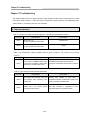
11.1 Abnormal operations žžžžžžžžžžžžžžžžžžžžžžžžžžžž žžžžž žžžžžžžžžžžžžžžžžžžžžžžžžžžžžžžžžžžžžžžžžžžžžžžž 11-1
11.2 T roubleshooting by each error code žžžžžžžžžžžžžžžžžžžžžžžžžžžžžžžžžžžžžžžžžžžžž žžžžžžž žžžžžžžžžžž 11-3
11.2.1 Error code ERR-1, ERR- 2 : hardware & system error žžžžžžžžžžžžžžžžžžžžžžžžžž žžžžžžžžžžžž žžžžžžž 11-3
11.2.2 Error code ERR-3 : communication command error žžžžžžžžžžžžžžžžžžžžžžžžžžžžžžžžžžžžžžžžžžžžžžžž 11-5
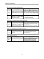
11.2.3 Error code ERR -4, ERR-5 : Receive monitor data error žžžžžžžžžžžžžžžžžžžžžžžžžžžžžžžžžžžžžžžžžžžž 11-7
11.2.4 Error code ERR -6, ERR-7 : Transmission monitor data error žžžžžžžžžžžžžžžžžžžžžžžžžžžžžžžžžžžžž 11-8
11.2.5 Error code ERR-8, ERR-9 : Error on dedicated communication žžžžžžžžžžžžžžžžžžžžžžžžžžžžžžžžžžžž 11-9
11.2.6 Error code ERR-10 : error on GMWIN connection žžžžžžžžžžžžžžžžžžžžžžžžžžžžžžžžžžžžžžžžžžžžžžžž 11-11
Appendix žžžžžžžžžžžžžžžžžžžžžžžžžžžžžžžžžžžžžžžžžžžžžžžžžžžžžžžžžžžžžžžžžžžžžžžžžžžžžžžžžžžžžžžžžžžžžžžžžžžžžž A-1~A-15
A.1 LED indication specificationžžžžžžžžžžžžžžžžžžžžžžžžžžžžžžžžžžžžžžžžžžžžžžžžžžžžžžžžžžžžžžžžžžžžžžžžžžžžžžžžžžžžžžžž A-1
A.1.1 Applicable type žžžžžžžžžžžžžžžžžžžžžžžžžžžžžžžžžžžžžžžžžžžžžžžžžžžžžžžžžžžžžžžžžžžžžžžžžžžžžžžžžžžžžžžžžžžžžžžžž A-1
A.1.2 LED indication specification during normal operationžžžžžžžžžžžžžžžžžžžžžžžžžžžžžžžžžžžžžžžžžžžžžžžžžžžžžžžžž A-1
A.1.3 LED indication specification during abnormal operation žžžžžžžžžžžžžžžžžžžžžžžžžžžžžžžžžžžžžžžžžžžžžžžžžžžžž A-5
A.1.4 LED indication specification during power on žžžžžžžžžžžžžžžžžžžžžžžžžžžžžžžžžžžžžžžžžžžžžžžžžžžžžžžžžžžžžžžžž A-6
A.2 Error code table žžžžžžžžžžžžžžžžžžžžžžžžžžžžžžžžžžžžžžžžžžžžžžžžžžžžžžžžžžžžžžžžžžžžžžžžžžžžžžžžžžžžžžžžžžžžžžžžžžžž A-7
A.2.1 Error code for user defined communicationžžžžžžžžžžžžžžžžžžžžžžžžžžžžžžžžžžžžžžžžžžžžžžžžžžžžžžžžžžžžžžžžžžž A-7
A.2.2 Error code for dedicated slave communicationžžžžžžžžžžžžžžžžžžžžžžžžžžžžžžžžžžžžžžžžžžžžžžžžžžžžžžžžžžžžžžž A-9
A.2.3 Error code for dedicated master communication žžžžžžžžžžžžžžžžžžžžžžžžžžžžžžžžžžžžžžžžžžžžžžžžžžžžžžžžžžžž A-11
A.3 Dimensions of appearancežžžžžžžžžžžžžžžžžžžžžžžžžžžžžžžžžžžžžžžžžžžžžžžžžžžžžžžžžžžžžžžžžžžžžžžžžžžžžžžžžžžžžžž A-12
Chapter 1 Introduction
Chapter 1 Introduction
This user’s manual describes Cnet (Computer network) I/F module of GLOFA PLC network system. Cnet is GLOFA
PLC network system using computer link module. Cnet has the connection function with different model to
communicate with communication devices of various different type protocols such as other company’s PLC and
computer, etc., and the function of modem communication to control remote PLC, and it has the following
characteristics.
q Because communication speed and communication mode (protocol, etc.) are directly controlled by user using
program operative in Frame Editor of Windows environment, connection with other company’s products is easy.
q Separate operations by channels are available through controlling each of other company’s protocol for channels
RS-232C and RS-422 (RS-485), and saving and using the protocol data controlled by user in internal flash
memory (128kbyte) are possible.
q Variable reading/writing and program reading/writing are possible by using dedicated protocol.
q Dedicated communication function suitable to multi-drop configuration connectable up to 32 units is provided.
q With modem communication function built-in, remote PLC can be controlled by GMWIN connection, dedicated
communication, and user defined communication.
q Communication port, RS-232C/RS-422 (RS-485) can be used by setting it to stand-alone or interlocking channel.
q Various communication speeds can be set from 300bps to 76,800bps.
q 1:1/1:N/N:M communication (if RS-422 channel used) is available.
q Communication types of full-duplex (RS-422/RS-232C) and half-duplex (RS-485) are supported.
q Channel RS-422 can be used as multi-drop communication channel, RS-485 by basic parameter setting.
q Modules can be mounted up to 8 units for GM1, GM2 and GM3, 4 units for GM4 and GM6, and 1 unit for GM7
(available only on the main base. And as linked with the basic module using an extended connector in case of
GM7.)
q With satisfactory self-diagnosis function and Loop-Back diagnosis function, diagnosis of errors is easy to make.
q With private functions of other products’ built-in, access is easy to such protocol as Modbus, A. B DF1. Ver.2.0
1-1
Chapter 1 Introduction
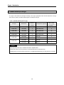
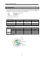
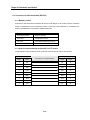
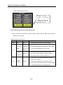
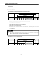
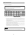
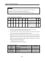
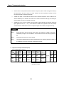
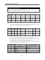
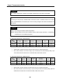
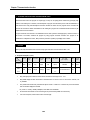
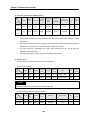
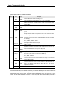
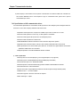
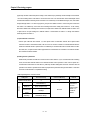
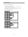
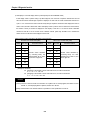
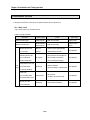
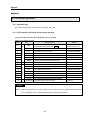
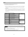
1.1 Module selection per CPU type
As 4 types of the modules are developed according to CPU types, appropriate module shall be selected for CPU type
and its service. [Table1.1] describes selection guide of module per CPU type.
[Table1.1] Module selection per CPU type
Number of
Module name
GLOFA-GMR[Note1]
G3L-CUEA
2
RS-422
GLOFA-GM1
G3L-CUEA
2
RS-232C/RS-422
8
GLOFA-GM2
G3L-CUEA
2
RS-232C/RS-422
8
GLOFA-GM3
G3L-CUEA
2
RS-232C/RS-422
8
GLOFA-GM4
G4L-CUEA
2
RS-232C/RS-422
4
G6L-CUEB
1
RS-232C
4
G6L-CUEB
1
RS-422
4
G7L-CUEB
1
RS-232C
1
G7L-CUEC
1
RS-422
1
GLOFA-GM6
GLOFA-GM7
channel
Configuration supported
Max. number
CPU type
mountable[Note2]
8[Note3]
Remark
[Note1] RS-422 channel only is available if mounted on duplicated base.
[Note2] This module can not be mounted on an extended base but on the basic base only.
[Note3] However, it can be mounted on slots No. 0~3 of duplicated extended base (for 8 slots) with max. 8 modules.
1-2
Chapter 1 Introduction
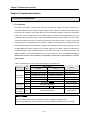
1.2 Functions of Version 2.0
This module has been operated in various application fields at home and abroad since released along with steady
increasing performance via continuous Version-Up to answer the diverse requests of customers and to reinforce the
reliability. Cnet I/F module has performed functional upgrade to Ver.2.0 reflected by the diverse requests of customers on
the basis of convenience, compliance and flexibility for users. Cnet I/F module Ver.2.0 has been designed so kept along
with the lower versions of products for functional compliance to use the established functions as same as 100%. Thus,
refer to this user’s manual for only added functions.
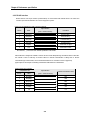
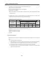
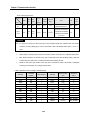
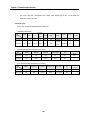
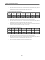
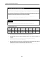
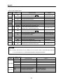
1.2.1 Version check [Note1]
O/S versions of Cnet I/F module are classified into CPU ROM O/S Ver. and Flash Memory O/S Ver. with the
differences below.
O/S Type
Class
Function
CPU O/S
FLASH O/S
Ver.2.0
Saving
location
Ver.2.0
Initial running and flash memory managing
CPU ROM
Ver.1.7 or less[Note2]
Performs all module
functions
CPU ROM
Ver. check
Using GMWIN’s I/O information function
Ver. Up
CPU ROM change
CPU ROM change
Function
Execution of all other functions than initial running
N/A
Flash memory
N/A
Ver. check
Using Frame Editor
N/A
Ver. Up
Using Frame Editor, upgrade by S/W
N/A
Saving
location
Remark
[Note1] Cnet I/F module versions are classified as based on CPU O/S Ver. Namely, functions for Ver. 2.0 or later
mean that CPU O/S is of Ver.2.0 or later.
[Note2] Since modules of Ver.1.7 or less have CPU O/S only, O/S upgrade via flash memory is unavailable.
1-3
Chapter 1 Introduction
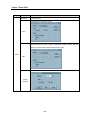
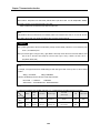
1) CPU O/S Ver. check
Cnet Ver.2.0 performs the most basic functions for initial running and flash memory operation and Ver.1.7 or less
performs all functions of Cnet. CPU O/S can be upgraded only by CPU change of Cnet I/F module. Versions of
Cnet I/F modules are classified on the basis of CPU O/S with the following procedure for version check.
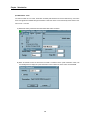
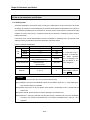
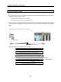
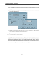
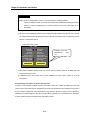
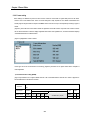
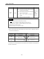
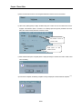
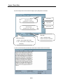
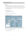
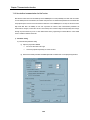
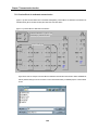
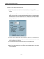
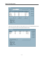
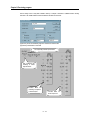
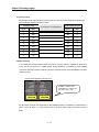
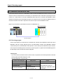
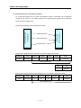
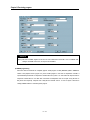
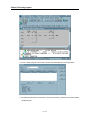
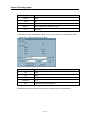
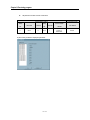
A) If [I/O info … ] selected after GMWIN [Online] connection, I/O information dialog box is displayed as below.
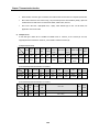
B) If applicable base is selected from I/O information dialog box, slot number in bold is displayed as a menu
available to select for communication module and special module. Click equivalent slot number to ‘GLOFA
Cnet’ to display the dialog box as in [Figure 1.1]. The succeeding figure to V in Vx.x indicates the version.
[Figure1.1] CPU O/S Ver. information
(a) Version information of Ver.1.7
(b) Version information of Ver. 2.0
1-4
Chapter 1 Introduction
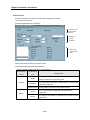
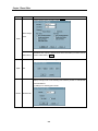
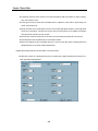
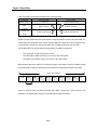
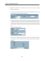
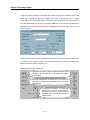
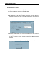
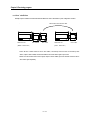
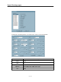
2) FLASH O/S Ver. check
For Cnet I/F module Ver. 2.0 or later, all functions to embody Cnet functions are saved in flash memory, and version
check and upgrade are available through Frame Editor. Flash O/S version can be checked by Frame Editor if CPU
O/S is of Ver. 2.0 or later.
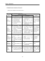
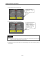
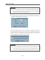
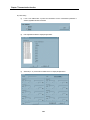
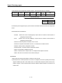
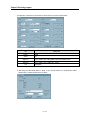
A) Select flash memory information with Frame Editor after Online connection.
B) Select slot number and O/S on which Cnet I/F module is mounted from the system information screen, and
click reading button to display the system information screen as below for version check of FLASH ROM.
1-5
Chapter 1 Introduction
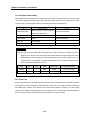
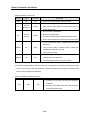
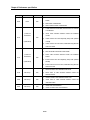
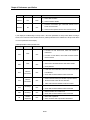
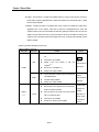
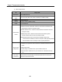
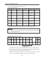
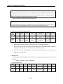
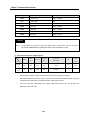
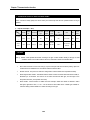
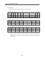
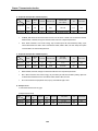
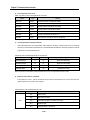
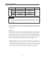
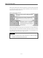
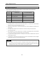
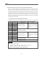
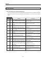
1.2.2 Added functions introduction of Version2.0
[Table1.2] shows configuration of main functions of Ver.2.0.
[Table1.2] Configuration of main functions added to Ver.2.0.
Comparison between contents
Items
Ver.1.0 ~ 1.7
Ver.2.0 or later
Remark
Mode change during operation
is available with On-line mode
added to module.
l Mode change with Frame
Editor
l Operating mode change is
available by remote control via
RS-232C channel.
Mode is changeable
by remote control
(only for RS-232C
channel).
Communication between Cnet
I/F modules is easy with
master function added to
dedicated mode.
l Communication between Cnet
I/F modules is available using
dedicated ‘Function Block’
without frame definition.
Slave operation is
same as established
dedicated mode
operation (lower Ver.
of Cnet I/F module
can be used).
A.B DF1 server protocol driver
built-in
l Modbus ASCII/RTU server
protocol driver built-in
Service is available
by downloading
communication
library in frame
editor.
l
Operating mode of module is
set via H/W using switch.
l Mode change during
operation is unavailable.
l No mode change function in
Frame Editor
l
On-line
Mode change
Communication
between
Cnet I/F modules is inconvenient as provided only with
dedicated
communication
slave function.
l Frame definition and GMWIN
program need to be composed in user defined mode.
l
Master
functions of
dedicated
communication
No communication driver of
main other company’s protocol
l Protocol is defined and
composed by user with
Frame Editor in user defined
mode.
l
l
other
company’s
communication
driver built-in
Support of
HEX input for
constant edit
Flash
memory
operation
Only ASCII data can be
input.
l Specified as ARRAY if HEX
input.
l
l
CPU change is required as
Cnet O/S uses internal ROM
of built-in CPU for Ver.-Up.
l
HEX can be set in constant
area.
Zero(00) code can’t
l Trans. data is transmitted in be input.
not ASCII but HEX.
l
l
l
1-6
Ver.-Up easy and
Flash memory is used by O/S.
additional functions
Other company’s dedicated
of other company’s
protocol can be used as
driver under considownloaded to flash memory.
deration
Chapter 1 Introduction
1.2.3 Established functions
Ver. 2.0 has been designed in 100% of compliance with the established versions and hardware configuration is the
same as the former versions of products as upgraded via software Ver.-Up without hardware change. Accordingly,
mounting and communicating connection with PLC CPU, user defined communication, dedicated communication,
GMWIN connection, modem communication function, etc. are available as same as in the established functions.
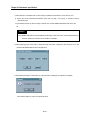
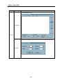
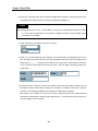
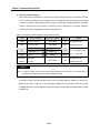
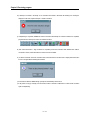
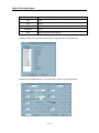
1.2.4 Frame Editor Version 2.0
To make additional configuration of Cnet Ver. 2.0 available, Frame Editor also shall be of Ver. 2.0. Since Frame
Editor Ver. 2.0 has been designed to keep compliance with the established program, the service for the former
versions of modules is allowed. However, the added functions in this user’s manual are available only for Cnet Ver.
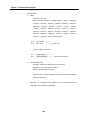
2.0. Select Help in the upper menu of Frame Editor to check the version. The screen below shows Frame Editor
information of Ver. 2.0.
1.2.5 Added function of Version2.0
This user’s manual describes the additional functions via module Ver.-Up and the established functions of Cnet
functions together. The additional functions provided only in Cnet Ver. 2.0 are so displayed as with Ver.2.0, and the
functions displayed with the mark above are available not in the former versions but only in Ver. 2.0.
1-7
Chapter 2 Definition of terms
Chapter 2 Definition of terms
This chapter describes the communication terms used in this user’s manual.
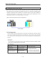
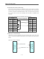
1) Communication type
A) Simplex
This is the communication type that data is transferred in constant direction. Information can not be transferred in
the reverse direction.
B) Half-Duplex
Data is transferred in two-way with one cable if time interval provided, though it can’t be transferred
simultaneously.
C) Full-Duplex
Data is simultaneously transferred and received in two-way with two cables.
2) Transmission type
This is divided into the following 2 types in consideration of the speed, safety and economy on transmission in binary
(bit composed of 0 and 1).
A) Serial transmission
This type transmits bit by bit via 1 cable. The speed of transmission is slow, but the cost of installation is low and
the software is simplified.
RS-232C, RS-422 and RS-485 are the examples.
Recv.
Trans.
2-1
Chapter 2 Definition of terms
B) Parallel transmission
This type is used in printer, etc., which transmits data in unit of 1 byte, so the speed is high and the accuracy of data
is reliable. However, the longer the transmission distance is, the higher the cost of installation is geometrically.
Trans.
Recv.
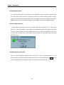
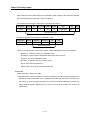
3) Asynchronous communication
This communication type transmits characters one by one synchronously in serial transmission. At this time,
synchronous signal (Clock, etc.) is not transmitted. Character code is transmitted with a start bit attached to the head of 1
character, and it is finished with a stop bit attached to the tail.
* For transmitting KOREA
Transmission
direction à
Stop Bit Parity Bit Data Bit
2-2
Start Bit
Chapter 2 Definition of terms
4) Protocol
This is communication rule established in relation between the transmission side and the receiving side of information in
order to send and accept information between two computers/terminals or more without error, effectively, and reliably.
In general, this specifies call establishment, connection, structure of message exchange form, re-transmission of error
message, procedure of line inversion, and character synchronization between terminals, etc.
5) BPS(Bits Per Second) and CPS(Characters Per Second)
BPS is a unit of transfer rate that represents how many bits are transferred per second. CPS is the number of the
characters transferring for a second. Generally, one character is 1Byte (8Bits), so CPS is the number of byte which
can be transferred per second.
6) Node
Node is a term that means the connected nodes of the data in the network tree structure, generally network is
composed of a great number of nodes, and is also expressed as the station number.
7) Packet
Packet, a compound term of package and bucket used for packet exchange type to send information as divided in a
unit of packet, separates transfer data into the defined length and adds a header that presents the opposite addresses
(station No., etc.) into it.
8) Port
Port is meant to be the part of the data process devices which sends or receives the data from a remote control
terminal in data communications, but in Cnet serial communication is meant to be the RS-232C or RS-422 port.
9) RS-232C
RS-232C is the interface to link a modem with a terminal and to link a modem with a computer, and is also the serial
communications specification established by EIA according to the recommendations of the CCITT. This is also used to
link the null modem directly as well as the modem linkage. The disadvantage is that the transfer length is short and
only 1 : 1 communication is available, and the specifications which recover this disadvantage are RS-422 and RS-485.
10) RS-422/RS-485
As one of the serial transmission specifications, its transfer length is long and multi (1 : N) connections are available
compared to RS-232C. The difference of these two specifications is that RS-422 uses 4 signals of TX(+), TX(-), RX(+)
and RX(-), while RS-485 has 2 signals of (+) & (-), where data is sent and received through the same signal line.
Accordingly, RS-422 executes the full-duplex type of communication and RS-485 executes the half-duplex type of
communication.
2-3
Chapter 2 Definition of terms
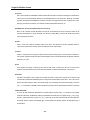
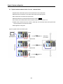
11) Half Duplex Communication
Two-way communication is available, however simultaneous communication of transmission & receiving isn’t
available. This communication type is applied to RS-485 for instance. It is used a lot for multi-drop communication type
which communicates via one signal line by several stations. Half Duplex Communication results from the transmission
characteristic performed by stations one by one not allowing simultaneous transmission by multi stations due to the data
damage of data impact caused by the simultaneous multi-transmission of the stations. The figure below shows an
example of structure based on Half Duplex Communication. Each station in communication with the terminal as linked
with each other can send or receive data via one line so to execute communication with all stations, where multi-master
is advantageously available.
Master station
]
Master station
Master station
Master station
Master station
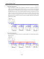
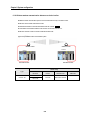
12) Full Duplex Communication
Two way-communication of simultaneous transmission & receiving is available. This communication type is applied to
RS-232C & RS-422.
Master station
Slave station
Slave station
2-4
Slave station
Slave station
Chapter 2 Definition of terms
Since the transmission line is separated from the receiving line, simultaneous transmission & receiving is available
without data impact, so called as Full Duplex Communication. The figure shows an example of structure based on RS422 of Full Duplex Communication. Since transmission terminal of the master station and receiving terminals of the
slave stations are connected to one line, and transmission terminals of the slave stations are linked with receiving
terminal of the master station, the communication between slave stations is unavailable with the restricted function of
multi-master.
13) BCC(Block Check Character)
As serial transmission may have signals distorted due to noise in transmission line, BCC is used as data to help
receiving side to check the signals if normal or distorted and to detect errors in signals as compared with the received
BCC after calculating BCC by receiving side itself using the data input to the front terminal of BCC.
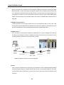
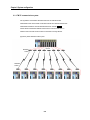
14) GMWIN function
This is the function to remotely perform programming, reading/writing user’s program, debugging, and monitor ing,
etc. without moving the physical connection of GMWIN in the network system where PLC is connected to Cnet I/F
module. Especially, it is convenient to control a remote PLC via modem.
Imaginary connection
RS-232C
Cable
Dial-up
Modem
RS-232C Cable
Aerial circuit
Aerial circuit
Dial-up
Modem
Relay station
* GMWIN : Programming software of GLOFA PLC for Windows.
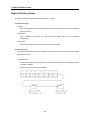
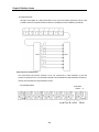
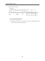
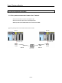
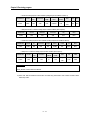
15) Frame
Frame is composed of transmitted and received data as in a specified form in data communication including additional
information of segment [station No., commands, parameter by command], control characters [ ENQ, ACK, EOT, ETX ]
for synchronization, parity for detecting error, and BCC. The structure of frame used for serial communication of Cnet
is as follows.
2-5
Chapter 2 Definition of terms
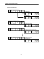
[Structure of general TX / RX frame]
Required frame
No.
Parameter by command
Segment
Result
Command
No.
treated
BCC
Station
Tail
ETX
Tail
ACK
Segment
Header
BCC
Command
EOT
ENQ
Header
Station
(1) Header : ASCII value indicating frame start.
(2) Tail : ASCII value indicating frame end.
(3) BCC (Block Check Character) : BCC as of check data for TX / RX frame is to inspect reliability of data with
such various methods as ADD, OR, EXR and MULTIPLY.
2-6
Chapter 3 Product specification
Chapter 3 Product specification
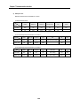
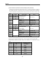
3.1 General specification
[Table 3.1] describes the environmental, electric and mechanical specifications of this module.
[Table 3.1] General specification
No.
Item
Specification
1
Operating temp.
2
Storage temp.
-25℃~+70℃
3
Operating moist
5~95%RH, non-condensing
4
Storage moist
Related specifications
0℃~+55℃
5~95%RH, non-condensing
For discontinuous vibration
Frequency
Acceleration
Amplitude
-
0.075mm
9.8 ㎨(1G)
-
10≤f< 57 ㎐
5
Vibration proof
57≤f≤150 ㎐
For discontinuous vibration
Frequency
Acceleration
Amplitude
-
0.035mm
4.9 ㎨(0.5G)
-
10≤f< 57 ㎐
57≤f≤150 ㎐
6
Impact proof
Each 10
IEC 61131-2
times in X,Y,Z
directions
* Max. impact acceleration:147 ㎨(15G)
* Authorized time :11 ㎳
* Pulse wave : Sign half-wave pulse (Each 3 times in X,Y,Z directions)
IEC 61131-2
Square wave impulse noise
±1,500V
Test spec. reference of LG
Industrial Systems
Voltage : 4kV(contact discharging)
IEC 61131-2,IEC 1000-4-2
27 ~ 500MHz, 10 V/m
IEC 61131-2,IEC 1000-4-3
Static electric discharging
Radiation electromagnetic field noise
7
Number
Noise proof
Power
Fast
Segment
module
Transient / burst
noise
Voltage
Digital
I/O
(24V or
more)
2kV
1kV
Digital I/O
(below 24V)
Analog I/O
communication
interface
0.25kV
IEC 61131-2,
IEC 1000-4-4
Ambient
No corrosive gas or dust
conditions
9 Operating height 2000m or less
8
10
Pollution level
2 or less
11
Cooling type
Natural air cooling
Remark
[Note1]
IEC(International Electrotechnical Commission): International non-governmental organization, which promote
international cooperation, establish international standard, and administer valuation system to its suitableness for
international standards of electric and electronic tech fields.
[Note2]
Pollution level: An index indicating pollution level of the operating environment which decides insulation
performance of the devices. For instance, Pollution level 2 indicates the state generally that only non-conductive
pollution occurs. However, this state contains temporary conduction due to condensing.
3-1
Chapter 3 Product specification
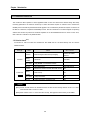
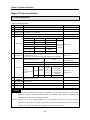
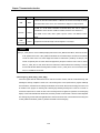
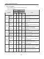
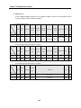
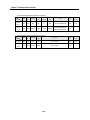
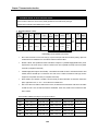
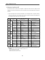
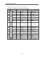
3.2 Performance specifications
[Table 3.2] Performance specification
Item
Specification
Remark
Serial communication
channel
RS-232C channel
RS-232C standards conformed
GM3/4/6/7
RS-422/485 channel[Note1]
RS-422/485 standards conformed
GM3/4/6/7
Modem connection
function
Remote communication[Note2] with external devices is available via public
telephone line by connecting external modem to the module.
Operating mode
(Operating mode can
be set by operating
switch for RS-232C
/422 channels respectively)
Data
type
Dedicated mode
Supporting multi-drop / 1:1 communication with
dedicated protocol of LG Industrial Systems
GM3/4/6/7
GMWIN mode
PLC remote control is available through
GMWIN connection function
GM3/4/6/7
User defined mode
Operated by user defined protocol
(for other company’s interface)
GM3/4/6/7
On-line mode
Ver. 2.0
Set by software when editing frame without
change of the mode switch
Other company’s
Dedicated Mode Ver.2.0
Interface[Note3] with other companies such
as Modbus and A.B DF1
GM3/4/6/7
With Frame Editor, basic parameter can be
selected[Note4] / GM7 is set in GMWIN
communication parameter.
GM3/4/6/7
Data Bit
7 or 8
Stop Bit
1 or 2
Parity
Even/Odd/None
Channel select
Stand-alone/interlocking channels can be selected
by operating mode switch [Note5]
Set in GMWIN communication parameter.
Synchronization type
Transmission
speed (bps)
Station No. setting
GM3/4/6/7
Asynchronous type
GM3/4/6
GM3/4/6
GM7
GM3/4/6/7
Any speed of 300/600/1200/2400/4800/9600/19200/38400/57600/
76800bps can be selected [Note6]
GM3/4/6
Any speed of 1200/2400/4800/9600/19200/38400/57600bps can be
selected [Note6]
GM7
Setting with Frame Editor(GM7 is set in GMWIN communication parameter)
is available up to 32 stations from 0 to 31 (valid only if operating mode is in
the dedicated mode or other company’s dedicated mode)
GM3/4/6/7
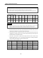
3-2
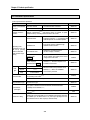
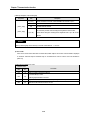
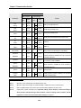
Chapter 3 Product specification
Item
Specification
Remark
Transmission
distance
RS-232C : Max. 15m(extendible by using modem)
RS-422 : Max. 500m
GM3/4/6/7
Diagnosis function
Loop-Back diagnosis / Indication of operation status with 16 LEDs during
operation (with 8 LEDs for GM6)
GM3/4/6
G3L-CUEA
160mA or less
G4L-CUEA
160mA or less
Current
G6L-CUEB
160mA or less
Consumption
G6L-CUEC
160mA or less
G7L-CUEB
100mA or less
G7L-CUEC
100mA or less
G3L-CUEA
375g
G4L-CUEA
211g
G6L-CUEB
94g
G6L-CUEC
102g
G7L-CUEB
195g
G7L-CUEC
193g
Weight
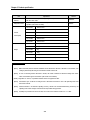
Remark
[Note1] With Frame Editor, RS-422 channel of GM3/4/6 can be selected from RS-422 or RS-485. In case of GM7, autosetting is performed by the wiring of communication module on basic unit.
[Note2] In case of connecting channel RS-232C to modem, the modem connection is selected in setting menu of RS232C communication type of Frame Editor. (G6L-CUEC is unavailable)
[Note3] Regardless of Version, only Modbus interface function is supported for GM7.
[Note4] Transmission spec. can be set according to each of RS-232C and RS-422 in case of the operating mode of the
stand-alone channel.
[Note5] Channel selection is set between operating mode by channel and stand-alone/interlocking channel by the
operating mode switch. Change of channel mode is impossible during operation.
[Note6] 76,800bps is provided in RS-422 or RS-485, and can be used in Cnet I/F module Ver. 1.3 or later.
3-3
Chapter 3 Product specification
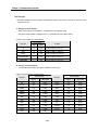
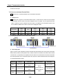
3.3 Cable specifications
When using communication channel, RS-422 or RS-485, twisted pair cable for RS-422 shall be used in consideration of
communication distance and speed. [Table 3.3] describes recommended specifications of cable. Also when using other cable
than recommended, the cable conformed to characteristics in [Table 3.3] shall be used.
q Item
.: Low Capacitance LAN Interface Cable
q Type
: LIREV-AMESB
q Size
.: 2P X 22AWG(D/0.254 TA)
q Manufacturer : LG Cable Co., Ltd
[Table 3.3] Specifications of twisted pair cable
1) Electric characteristics
Test item
Conductor resistance
Unit
Ω / km
Withstanding voltage(DC)
V/1min
Insulation resistance
Static electricity capacity
Characteristics impedance
MΩ - km
Pf / M
Ω
Characteristics
59 or less
Withstands for 1 min.
at 500V
1,000 or more
45 or less
120 ± 12
2) Characteristics of appearance
Item
Core number
Size
Conductor
Composition
Outer dia.
Thickness
Insulator
Outer dia.
Pair
AWG
No. / mm
mm
mm
mm
Solid cable
2
22
1 / 0.64
0.64
0.55
1.64
[Figure 3.1] Structural drawing
Conductor
Insulator
AL / MYLER Tape
Ground
Braided material
3-4
Test conditions
Normal temp.
Stranded cable
2
22
7 / 0.254
0.76
0.55
1.76
In air
Normal temp
1kHz
10MHz
Chapter 3 Product specification
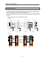
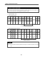
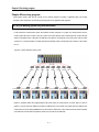
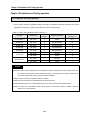
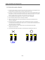
3.4 Terminating resistance
For communication via RS-422 channel, terminating resistance from external must be connected. Terminating resistance has
the function to prevent distortion of signal by reflected wave of cable for long-distance communication, and the same resistance
(1/2W) as characteristic impedance of cable must be connected to terminal of network.
When using the recommended cable in 3.3, connect terminating resistance of 120Ω to both ends of cable. Also when using
other cable than recommended, the same resistance (1/2W) as characteristic impedance of cable must be connected to both
ends of cable.
1)
How to connect terminating resistance during RS-422 connection
q GM3/4/6 unit
PLC #1
PLC #2
PLC #(N-1)
PLC #N
q GM7 unit
RXA
RXA
RXA
RXA
RXB
RXB
RXB
RXB
TXA
TXA
TXA
TXA
TXB
TXB
TXB
TXB
SG
SG
SG
SG
・
・
・
・
・
・
・
・
PLC #2
PLC #(N-1)
PLC #1
3-5
PLC #N
Chapter 3 Product specification
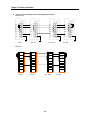
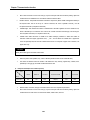
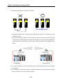
2)
How to connect terminating resistance during RS-485 connection
q GM3/4/6 unit
PLC #1
PLC #2
PLC #(N-1)
PLC #N
q GM7 unit
RXA
RXA
RXA
RXA
RXB
RXB
RXB
RXB
TXA
TXA
TXA
TXA
TXB
TXB
TXB
TXB
SG
SG
SG
SG
・
・
・
・
・
・
・
・
PLC #2
PLC #(N-1)
PLC #1
3-6
PLC #N
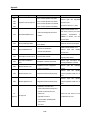
Chapter 3 Product specification
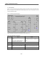
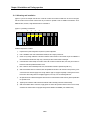
3.5 Structure
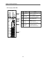
3.5.1 Part names of G3L-CUEA
G3L-CUEA
RS-232C
RS-422
RUN/BPS
TX/BPS
RX/BPS
ACK/DATA- BIT
NAK/PARITY
ERR/EVEN- ODD
MODEM/STOP-BIT
SYS-RUN
RUN/BPS
TX/BPS
RX/BPS
ACK/DATA- BIT
NAK/PARITY
ERR/EVEN- ODD
RS-485/STOP-BIT
SYS-ERR
No.
①
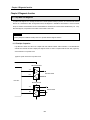
①
Indication of operating status of G3L-CUEA
section
(see Appendix A)
②
Display switch
③
Mode switch
③
MODE
④
⑤
RS-232C
④
RS-422
RDA
RDB
⑤
SDB
SG
FG
3-7
Contents
LED displaying
②
DISPLAY
SDA
Name
Switch for indication of parameter and
station number (see Appendix A)
Setting of operation mode
(see 4.1)
RS-232C
RS-232C connector for
Connector
connection with external devices
RS-422/485
RS- 422/485 connector for
Connector
connection with external devices
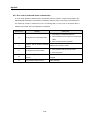
Chapter 3 Product specification
3.5.2 Part names of G4L-CUEA
G4L-CUEA
RUN/BPS
TX/BPS
RX/BPS
ACK/DATA
NAK/PARITY
ERR/EVEN-ODD
MODEM/STOP
SYS-RUN
RS-232C
RUN/BPS
TX/BPS
RX/BPS
ACK/DATA
NAK/PARITY
ERR/EVEN-ODD
RS-485/STOP
SYS-ERR
No.
①
RS-422
②
DISPLAY
①
④
RS-232C
Indication of operating status of G4L-
section
CUEA (see Appendix A)
Display switch
③
Mode switch
④
⑤
Switch for indication of parameter and
station number (see Appendix A)
Setting of operation mode
(see 4.1)
RS-232C
RS-232C connector for
Connector
connection with external devices
RS-422/485
RS- 422/485 connector for
Connector
connection with external devices
RS-422
RDA
RDB
SDA
Contents
LED displaying
②
③
MODE
Name
⑤
SDB
SG
FG
3-8
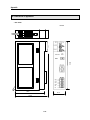
Chapter 3 Product specification
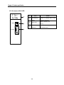
3.5.3 Part names of G6L-CUEB
RUN
TX
RX
ACK
NAK
COM-ERROR
MODEM
SYS-RUN/ERR
①
G6L-CUEB
MODE
No.
①
②
②
③
RS-232C
Name
Contents
LED displaying
Indication of operating status of G6L-
section
CUEB (see Appendix A)
Mode switch
Setting of operation mode
(see 4.1)
RS-232C
Connector for connection
Connector
with external devices
③
3-9
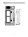
Chapter 3 Product specification
3.5.4 Part names of G6L-CUEC
RUN
TX
RX
ACK
NAK
COM-ERROR
RS-485
SYS-RUN/ERR
No.
①
①
G6L-CUEC
②
MODE
②
③
SDA
SDB
Name
Contents
LED displaying
Indication of operating status of G6L-
section
CUEC (see Appendix A)
Mode switch
Setting of operation mode
(see 4.1)
RS-422/485
Connectors for connection
Connector
with external devices
③
RDA
RDB
SG
FG
RS-422 / 485
3-10
Chapter 3 Product specification
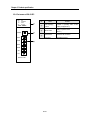
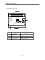
3.5.5 Part names of G7L-CUEB
¬
GLOFA
PWR
TX
RX
G7L-CUEB
CTS
DSR
CD
¯
PROGRAMMABLE
LOGIC
CONTROLLER
D-SUB
®
-
No.
TM/TC MODE
ON Ö OFF
Name
Contents
①
LED displaying section
See LED display.
②
RS-232C connector
Connectors for connection with external
devices
③
Mode switch
For selecting of TM/TC operation
¯
For extended connector
Connectors for connection with digital I/O
module and special module
3-11
Chapter 3 Product specification
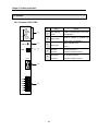
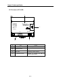
3.5.6 Part names of G7L-CUEC
¬
GLOFA
PWR
G7L-CUEC
®
RXD
PROGRAMMABLE
LOGIC
CONTROLLER
TXD
-
No.
Name
Contents
①
RS-422/485 interface
Connectors for connection
with external devices
②
LED displaying section
See LED display.
③
For extended connector
Connectors for connection with digital I/O
module and special module
3-12
Chapter 4 Performance specification
Chapter 4 Performance specification
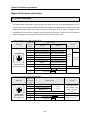
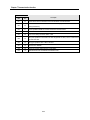
4.1 Operation mode setting
The operation mode of this module is set with operation mode switch on the front, and interlocking/stand-alone mode or
operation mode for each channel is determined according to the operation mode. Setting method of operation mode is after
selecting required mode adjusting switch values of operation mode with power off, set by power on. Operation mode is
unchangeable even if switch values of operation mode are changed during operation, so surely after power off, change the
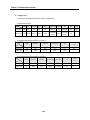
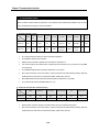
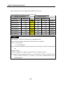
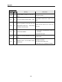
switch values. [Table4.1] & [Table4.2] describe the operation modes according to switch values.
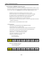
[Table4.1] Operation mode of G3L-CUEA/G4L-CUEA
Switch value
Switch type
of operation
mode
0
1
2
8
7
9
6
5
0
4
1
3
2
Applicable module
(G3L-CUEA/G4L-CUEA)
Operation mode
RS-232C
Remark
RS-422
User defined communication User defined communication
Dedicated communication
mode[Note1]
Dedicated communication
User defined communication User defined communication
3
Dedicated communication
Dedicated communication
4
User defined communication
Dedicated communication
5
Dedicated communication
User defined communication
6
GMWIN
User defined communication
7
GMWIN
Dedicated communication
Loop-Back
Loop-Back
8
Interlocking
Flash writing mode Ver. 2.0
Off-line
mode
[Note3]
Stand-alone
mode[Note2]
Self-diagnosis mode
[Note4]
On-line mode Ver. 2.0 [Note5]
9
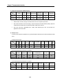
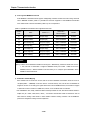
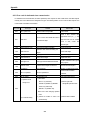
[Table4.2] Operation mode of G6L-CUEB/G6L-CUEC
Switch value
Switch type
of operation
Operation mode
Remark
mode
8
7
9
6
5
0
4
1
3
2
0
User defined communication
1
Dedicated communication
2
GMWIN service
3
Loop-Back
Off-line
4~7
Not used
Applicable module
8
Flash writing mode Ver. 2.0
(G6L-CUEB/CUEC)
9
On-line mode Ver. 2.0
4-1
mode
G6L-CUEC doesn’t
support GMWIN service
(supports only G6LCUEB)
Not used in Ver.1.0 [Note6]
Chapter 4 Performance specification
Remark
[Note1]
In interlocking mode, main channel is set to RS-232C, RS-422 channel is operated as data path of channel
RS-232C (channel RS-422 disabled), and transmission spec. is operated according to setting value of RS232C.
[Note2]
RS-232C/RS-422 channels are operated separately in stand-alone mode
[Note3] Off-line mode sets the operation mode with mode switch. (existing mode)
[Note4]
Supported only in Ver.2.0 or later and used for downloading of library file of other company’s dedicated
communication protocol with flash memory of Cnet I/F module.
[Note5] Supported only in Ver.2.0 or later and used for setting the operation mode of module with Frame Editor.
[Note6] When setting in mode not used, do not set Cnet I/F module because both channels of RS-232C/RS-422 are
not operated.
[Note7] Separate setting of operation mode for GM7 series isn’t required, however, the operation is decided according
to communication parameter of GMWIN.
4-2
Chapter 4 Performance specification
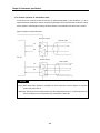
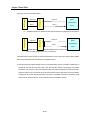
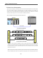
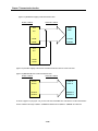
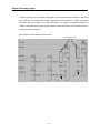
4.1.1 Channel operation in interlocking mode
In interlocking mode, channels RS-232C and RS-422 are operated as interlocked with each other. In other words, the
data received via channel RS-232C is sent via channel RS-422, and the data received via channel RS-422 is sent via
channel RS-232C in reverse.
In interlocking mode, main channel is automatically set to RS-232C, data is transmitted/received via channel RS-232C
only, and the data is received via channel RS-422 is automatically sent via channel RS-232C without receiving into Cnet
I/F module.
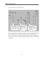
[Figure4.1] Data flow in interlocking mode
RS-232C
RS-232C cable
RS-422 channel
RS-422 cable
Data flow
Remark
[Note1] In interlocking mode, data is transmitted/received in accordance with setting values of channel RS-232C
transmission spec. and the transmission spec. of RS-422 can be ignored.
[Note2] In interlocking mode, modem can not be connected to RS-232C. During connecting modem, it must be
used only after setting to the stand-alone mode. In case that modem is set to be used in interlocking mode,
channel RS-232C is operated as in null modem mode.
[Note3] GM6 and GM7 series don’t support interlocking mode.
4-3
Chapter 4 Performance specification
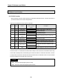
4.1.2 Channel operation in stand-alone mode
In stand-alone mode, channels RS-232C and RS-422 are operated independently to allow simultaneous Tx / Rx in
separate transmission specifications. Therefore, transmission specifications can be set per RS-232C and RS-422 channel,
and the operation is started/stopped according to channels. Data flow of each channel in stand-alone mode is as below.
[Figure 4.2] Data flow in stand-alone mode
RS-232C channel
RS-232C cable
TX
RX
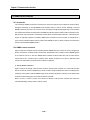
PLC cpu
RS-422 channel
RS-422 cable
TX
RX
Remark
[Note1] Mode change during operation is unavailable. The mode switch value of the front shall be set to required
position surely after power off.
[Note2] Each operation per channel shall be started surely after setting transmission spec. of channels RS-232C and
RS-422 and writing for each channel of RS-232C and RS-422 in Frame Editor.
4-4
Chapter 4 Performance specification
4.1.3 Channel operation in self diagnosis mode(Loop-Back)
Loop-Back diagnosis is a function to check if communication channel is normally operated by itself without connection with
external devices, and is operated only if the mode switch is in Loop-Back mode. For the details of operation method, see
‘Chapter 9 Diagnosis function’.
4-5
Chapter 4 Performance specification
4.2 Method of serial interface
4.2.1 RS-232C interface
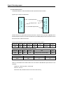
Channel RS-232C uses 9-pin connector (Female) for communication with external devices. The names and functions of
pins and data directions are as shown in the figure below.
[Figure 4.3] Pin specifications of 9-pin connector for RS-232C
Signal direction
(Cnet<-->external
devices)
Pin No.
Name
Contents
Description
1
CD
Carrier Detect
Reports carrier detection of DCE to DTE
2
RxD
Received Data
Received data signal
3
TxD
Transmitted Data
4
DTR
5
SG
Signal Ground
6
DSR
Data Set Ready
Reports communication ready of DCE to DTE
7
RTS
Request To Send
Requests data transmission from DTE to DCE
8
CTS
Clear To Send
9
RI
Ring
Transmitted data signal
Data Terminal
Reports communication ready of DTE to DCE
Ready
Ground line for signal
Reports data transmission available from DCE
to DTE
Reports ringing tone received from DCE to DTE
Channel RS-232C can communicate with external devices directly and also with remote communication devices using
modem. When connecting modem, communication type of RS-232C must be set to ‘modem’with Frame Editor, and when
not using modem, it must be set to null modem. But when the channel mode is as interlocked, modem can not be connected
because it is operated as in null modem even if set to modem.
Remark
[Note1] DTE:Data Terminal Equipment (Cnet I/F module)
[Note2] DCE:Data Communication Equipment (external modem)
4-6
Chapter 4 Performance specification
1) How to connect RS-232C connector during modem connection
Cnet I/F module can communicate with devices of long distance as connected with modem. Modem and RS-232C
channel shall be connected as in [Figure4.4] below.
[Figure 4.4] Cable connection between RS-232C and modem
Cnet(9-PIN)
Pin No.
Name
1
Connection No. and signal direction
Modem side(25-PIN)
Name
Pin No.
CD
CD
8
2
RXD
RXD
3
3
TXD
TXD
2
4
DTR
DTR
20
5
SG
SG
7
6
DSR
DSR
6
7
RTS
RTS
4
8
CTS
CTS
5
9
RI[Note]
RI
22
[Note] No. 9, RI signal is not used in Cnet I/F module.
2) How to connect connector for RS-232C in null modem mode
In null modem, connector can be connected in 7-wire (with handshake) or 3-wire (without handshake) type.
[Figure 4.5] as of 7-wire connection shows connection drawing when controlling CD(Carrier Detect) signal line by
external devices.
[Figure 4.5] Connection of 7-wire type (with handshake)
Cnet(9-PIN)
Computer/communication
Connection No. and signal direction
devices
Pin No.
Name
Name
1
CD
CD
2
RXD
RXD
3
TXD
TXD
4
DTR
DTR
5
SG
SG
6
DSR
DSR
7
RTS
RTS
8
CTS
CTS
9
RI
RI
4-7
Chapter 4 Performance specification
If CD signal is not controlled by external devices, it must be connected in 3-wire type connection as in [Figure 4.6].
Recent PC does not control CD signal line, so when connecting with PC, it must be connected in 3-wire type.
[Figure 4.6] Connection of 3-wire type (without handshake)
Cnet(9-PIN)
Computer/communication
Connection No. and signal direction
devices
Pin No.
Name
Name
1
CD
CD
2
RXD
RXD
3
TXD
TXD
4
DTR
DTR
5
SG
SG
6
DSR
DSR
7
RTS
RTS
8
CTS
CTS
9
RI
RI
Remark
[Note1]
When in null modem communication via RS-232C channel, wiring without handshake shall be
performed on the side of Cnet I/F module as in [Figure4.6] even if only 3 wires are used in external
devices.
[Note2]
If not wired as in [Figure4.6], transmission in Cnet I/F module isn’t available, however, receiving via
Cnet I/F module is allowed.
4-8
Chapter 4 Performance specification
4.2.2 RS-422 interface
Channel RS-422 uses 6-pin connector (Terminal Block) for communication with external devices. The names and
functions of pins and data directions are as shown in [Figure 4.7] below.
[Figure 4.7] Pin specifications of 6-pin connector for RS-422
Signal direction
Pin No.
Name
1
RDA(RXA)
Received data(+)
2
RDB(RXB)
Received data(-)
3
SDA(TXA)
Transmitted data(+)
4
SDB(TXB)
Transmitted data(-)
5
S.G(SG)
Ground line for signal
6
F.G
Ground line for frame
(Cnet<-->external devices)
Description
q Contents in ( ) of the name mean terminal specification of G7L-CUEC.
Channel RS-422 is designed as available to connect RS-422 and RS-485(multi-drop) with external devices. When RS422 channel is used as multi-drop, set channel RS-422 to RS-485 communication in setting menu of RS-422
communication type of Frame Editor, and use the terminals of RS-422 as connected as shown in [Figure4.9].
[Figure4.8] shows an example of connecting communication cable in RS-422 communication.
[Figure 4.8] RS-422 connection
Computer link side
Signal direction
(Cnet<--->external devices)
External communication device
Pin No.
Name
1
RDA(RXA)
SDA
2
RDB(RXB)
SDB
3
SDA(TXA)
RDA
4
SDB(TXB)
RDB
5
S.G(SG)
S.G
6
F.G
F.G
4-9
Chapter 4 Performance specification
[Figure 4.9] RS-485 connection
Computer link side
Signal direction
External communication
(Cnet<--->external devices)
device
Pin No.
Name
1
RDA(RXA)
SDA
2
RDB(RXB)
SDB
3
SDA(TXA)
RDA
4
SDB(TXB)
RDB
5
S.G(SG)
S.G
6
F.G
F.G
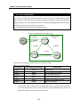
[Figure4.9] shows how to connect RS-485 multi-drop communication. In case of multi-drop communication, to connect with
external devices, RDA and SDA, RDB and SDB of RS-422 channel shall be connected each other. At this time halfduplex communication is run sharing Tx/Rx line, so RS-422 channel mode shall be applied as set to RS-485 in Frame
Editor.
Remark
[Note1] G7L-CUEC does not use Frame Editor and is designed to be set automatically by communication parameter
of GMWIN.
4-10
Chapter 4 Performance specification
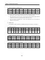
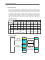
4.3 How to set transmission specifications
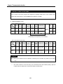
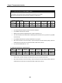
4.3.1 Setting items
Transmission specifications of transmission speed and data type of data/stop bit are set by Frame Editor in this module.
Accordingly, user is required to set the following items in accordance with the transmission specifications of the system to be
used. Transmission specifications set via Frame Editor are to write by Cnet I/F module. Since the contents with the writing
completed are saved in flash memory of computer link inside, they are still saved as unchanged if powered off until rewritten in Frame Editor.
In stand-alone mode, channels RS-232C/RS-422 shall be set separately. In interlocking mode, only RS-232C needs
setting because they are operated by transmission specifications of RS-232C channel.
[Table 4.3] Transmission specifications
Item
Setting value
Basic value[Note1]
Data Bit
7 or 8
8bit
Data
Stop Bit
1 or 2
1bit
type
Start Bit
1
1bit
Parity
Even/Odd/None
None
Transmission speed(bps)
RS-232C channel mode
300/600/1200/2400/4800/
9600/19200/38400/76800[Note2]
Modem/null modem[Note3]/
38400bps
Null modem
dedicated modem
RS-422 channel mode
RS-422 / RS-485[Note4]
Remark
If in stand-alone mode, 2
channels of RS-232C/RS422
operate
separately,
and if in interlocking mode,
they are operated in RS232C setting mode.
RS-422
*Dedicated mode
Station No.
0 ~ 31
0
[Note5]
*Other company’s dedicated
mode Ver.2.0
Remark
[Note1] Basic value means the basic value as set as released from the factory.
[Note2] 76800bps is provided for RS-422/RS-485 channel and serviceable in module Ver. 1.3 or later. Speed of RS232C channel is allowed up to 38400bps.
[Note3] Modem mode can be set only if in operation mode separate. If in interlocking mode, it is operated with null
modem mode.
[Note4] If set to RS-485, RS-422 channel is converted to half-duplex communication mode.
[Note5] Station No. is valid only in dedicated mode and other company’s dedicated mode and can be set differently
according to each channel of RS-232C/RS-422. In user defined and GMWIN modes, station No. set is
insignificant.
4-11
Chapter 4 Performance specification
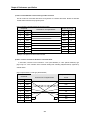
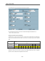
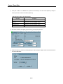
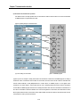
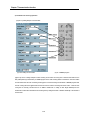
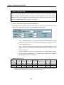
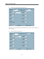
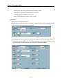
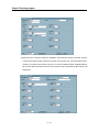
4.3.2 How to set
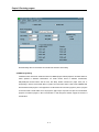
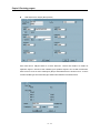
Transmission specifications are set by Frame Editor with the setting sequence as below.
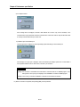
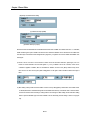
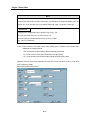
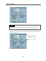
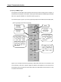
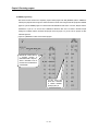
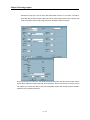
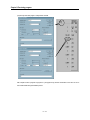
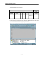
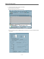
1) Run Frame Editor in Windows.
2) The following initial setting screen is displayed
Selection area of
communication
channel
Setting area
of basic
parameter
Setting area
of user defined
frame
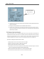
3) Select communication channel to set in the above screen.
4) Select communication type referring to the table below.
[Table 4.4] Example of criteria for selection of communication type
Communication
Communication
channel
type
Modem
RS-232C
Null modem
Dedicated modem
RS-422
RS-422
RS-485
Selection criteria
For communication with remote PC or remote connection with GMWIN via
public line (telephone line) using dial-up modem
For communication with local PC or external devices as connected with
cable directly. (within 15m)
For line-dedicated communication using dedicated modem
For 1:N communication of full-duplex type with external devices.
(within 500m)
For multi-drop communication of half-duplex type with external devices.
( within 500m)
4-12
Chapter 4 Performance specification
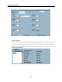
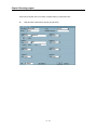
5) Enter station No. for dedicated mode or other company’s dedicated mode. Station No. can be set from 0 to 31.
6) Set the other basic parameters(communication speed, data bit, parity , and stop bit) in accordance with the
communication type.
7) If parameters have been set, write according to channels. First, connect GMWIN cable between CPU of PLC and
PC.
Remark
[Note1] GMWIN cable shall be connected between RS-232C port of PLC CPU and PC. If linked with RS-232C port
of Cnet I/F module, the connection via Frame Editor isn’t available.
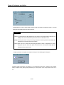
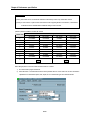
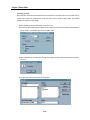
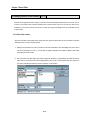
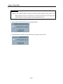
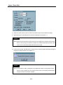
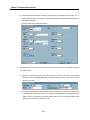
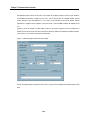
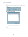
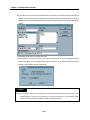
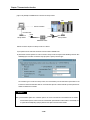
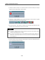
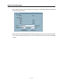
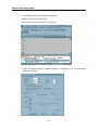
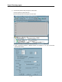
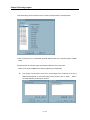
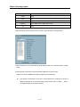
8) Select [Option]-[port] in Frame Editor to display the dialog box below. Continuously select serial port of PC side
connected with GMWIN cable and click on the [OK] button.
.
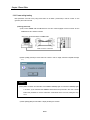
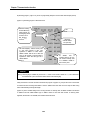
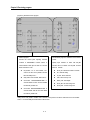
9) Select [Online]-[Connect] to connect with PLC. If the screen below is displayed, the connection is completed.
If the connection failed, two causes are expected as follows.
4-13
Chapter 4 Performance specification
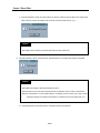
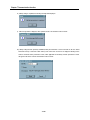
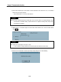
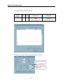
A) If no response in time
If the message above is displayed, RS-232C cable between PC and PLC may not be connected, or the
connection status may be abnormal. Check the connection status of RS-232C cable to verify that RS-232C cable
is correctly connected with loader port of PLC CPU.
B) If failed to open communication port
The message below is displayed as caused separately by abnormal setting of communication port.
If the message ‘Can’t open port’is displayed, check communication port setting in option menu of Frame Editor if
set as repeated with the mouse or other devices, and then try re-connection.
Remark
[Note1] PLC connection is unavailable with Frame Editor if connected with PLC in GMWIN program. If the
message above ‘Can’t open port’is displayed, check if GMWIN is connected in GMWIN program.
[Note2] To the contrary, connection to GMWIN as connected via Frame Editor isn’t allowed
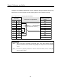
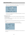
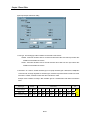
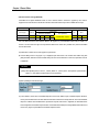
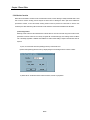
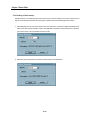
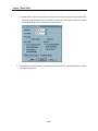
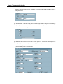
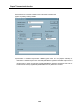
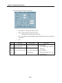
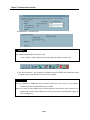
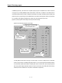
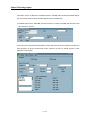
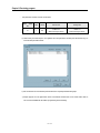
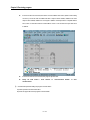
10) After the connection is completed, select [Online]-[Write] to write parameters.
4-14
Chapter 4 Performance specification
In Write dialog box as above, set the position where the module to be written is mounted with slot No., and select
writing with communication option set to ‘basic parameter’.
Remark
[Note1] If user defined frame has been prepared, let it set to frame in communication option to write frame only.
Similarly to this, if ‘All’is selected, basic parameter and frame can be written at a time.
[Note2] Check the power status of PLC prior to writing of parameter or frame. If powered off while writing, data
in flash memory of Cnet I/F module may be crushed.
[Note3] Switch over PLC to STOP mode when writing parameter and frame. If writing while PLC running,
writing error may occur. In this case, power off and then let it on back to perform writing again after
switching over PLC to STOP mode
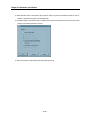
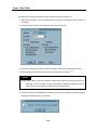
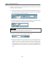
If writing of parameters is completed, the completion message as in the following figure is displayed.
If parameter writing is performed, Cnet operation of the correspondent channel stops. Therefore, after parameter
writing is completed, select [Online]-[Change RUN/STOP] to switch operation of the correspondent channel over to
run.
4-15
Chapter 4 Performance specification
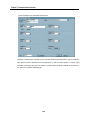
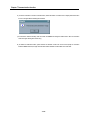
Select the slot No. of computer link module and the channel of operation to switch over in the dialog box for
operation change and click on [Run] button to start the correspondent channel.
In these methods, run the correspondent channel to start operation after basic parameters are set and written
according to channels RS-232C/RS-422.
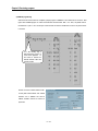
4.3.3 Reading setting values
Basic parameters saved in flash memory of Cnet I/F module can be confirmed by reading through Frame Editor or
checking through LED display.
How to read basic parameters through Frame Editor is specified as follows.(refer to ‘Appendix A, LED indication
specification’for checking through LED display.)
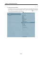
1) Select [Online]-[Connect] in basic screen of Frame Editor to finish the connection with PLC. How to connect is same as
in 4.3.2.
2) Select [Online]-[Read] to display the dialog box below if the connection has been completed.
Enter Cnet’s slot No., communication type and communication option herein and then select [Read].
If reading is finished, the basic values which have been read are displayed in basic screen of Frame Editor and can
be saved in a file.
4-16
Chapter 4 Performance specification
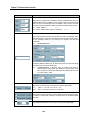
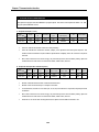
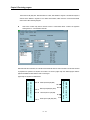
4.3.4 Transmission specification setting of GM7 series
Transmission specification of GM7 series is composed as set inside the communication parameter of GMWIN without Frame
Editor.
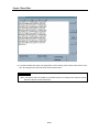
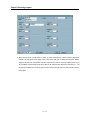
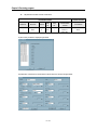
1) Select and execute the communication parameter after GMWIN is started.
2) Select communication type of the communication parameter in accordance with the contents to set.
Setting area of basic
parameters of GM7
unit
4-17
Chapter 4 Performance specification
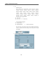
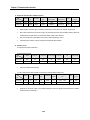
3) Select self-station number, communication speed, parity bit, data bit, stop bit and communication channel of Cnet I/F
module to communicate among items in communication type.
4) If parameter setting of communication type is completed, enter protocol and transmission mode below and then select
writing of communication parameter for program.
5) Start and execute the correspondent program after writing is performed.
4-18
Chapter 4 Performance specification
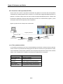
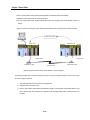
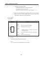
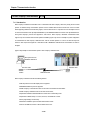
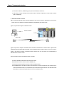
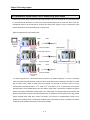
4.4 How to connect to modem
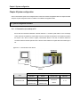
Cnet I/F module has a function for long-distance communication via RS-232C channel using public line. How to connect to
public line using Cnet I/F module is as follows
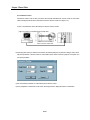
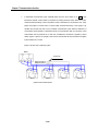
1) Dedicated modem communication via dedicated line
2) Dial-up modem communication via normal telephone line
Since these two types of communication differ from each other according to characteristics of the line, they shall be used with
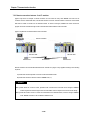
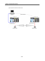
modem connection as set differently by Frame Editor. [Figure4.10] shows long-distance communication using dedicated
modem.
`[Figure 4.10] Example of dedicated modem communication
RS-232C Cable
MODEM
RS-232C CABLE
MODEM
Dedicated line
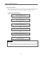
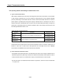
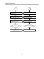
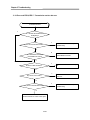
Connection sequence of this module to the modem is as below.
Set the basic parameter of Cnet I/F module as agreed with modem.
↓
Set the initial value of dedicated modem or dial-up modem.
↓
Connect modem to Cnet I/F module with modem connection cable.
↓
If abnormal
Power on Cnet I/F module and modem, and check if LED on.
↓
If normal
Modem communication starts operation.
4-19
→
Refer to chapter 4, for
troubleshooting.
Chapter 4 Performance specification
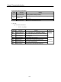
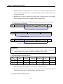
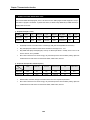
4.4.1 Connection to dedicated modem (RS-232C)
4.4.1.1 Modem selection
Performance of dedicated modem communication with Cnet I/F module depends on the condition and status of dedicated
modem and dedicated line. Since low-performance modem or inferior line causes deterioration of communication, the
modem as specified below is recommended for reliable communication.
Item
Specification
Communication speed
More than 2400 bps
Flow control
CTS/RTS Flow Control
Line control
Full-duplex/Half-duplex (2-line/4-line)
RTS-CTS delay
Within 500msec
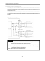
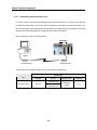
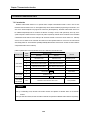
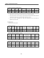
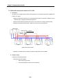
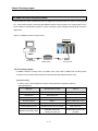
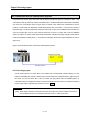
4.4.1.2 How to connect dedicated modem with Cnet I/F module
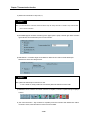
Connect dedicated modem with Cnet I/F module via RS-232C channel using 9-pin cable as wired as below.
Cnet(9-PIN)
Pin No.
Name
1
Connection No. and signal direction
Modem side(25-PIN)
Name
Pin No.
CD
CD
8
2
RXD
RXD
3
3
TXD
TXD
2
4
DTR
DTR
20
5
SG
SG
7
6
DSR
DSR
6
7
RTS
RTS
4
8
CTS
CTS
5
9
RI
RI
22
4-20
Chapter 4 Performance specification
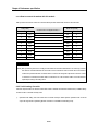
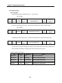
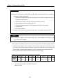
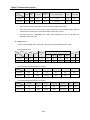
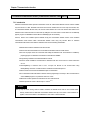
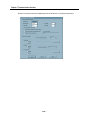
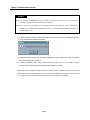
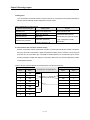
4.4.1.3 Dedicated modem setting
Most dedicated modems are designed to set operation mode via dip switch or LED display window according to modem
manufacturers. Operation type needs setting as agreed with communication type with Cnet I/F module referring to user’s
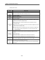
manual for modem. The following items related to communication with Cnet I/F module shall be set.
Item
Setting contents
Remark
Select according to modem speed and
Communication speed
status of communication line
Same as Cnet I/F module
Data type
Asynchronous 10 bit[Note1]
Set to basic setting values of Cnet
RTS-CTS delay
0msec
Set to the smallest value
DTR control
ON compulsorily
Communication mode
Set according to 4-line/2-line
Remark
[Note1] Data type needs setting agreed with communication type of Cnet I/F module as in asynchronous type as
supported only by Cnet I/F module. The number of bits shall be calculated according to setting values of data
bit/stop bit/parity bit of basic parameters in Cnet I/F module. Start bit of Cnet I/F module is always set to 1 and
parity bit possesses 1 bit regardless of Even/Odd. The table below shows an example of setting the number
of bits according to basic parameters set in Cnet.
Start
Data
Stop
Parity
Number of bits
Ex. of Data-Bit calculation
1 always
8
1
None
10 bits
1 + 8 + 1 + 0 = 10 bits
1 always
7
0
Even
9 bits
1 + 7 + 0 + 1 = 9 bits
4.4.1.4 How to set
Cnet I/F module shall be set to stand-alone channel for dedicated modem communication and is, regardless of operation
mode available to communicate distantly via dedicated modem in all the modes of user defined, dedicated communication
and GMWIN modes. [Table4.3] shows operation modes where modem connection is available. As in Table, modem
connection is not available in interlocking mode but only in stand-alone mode. If connecting with modem after interlocking
mode is set, beware of modem communication which isn’t available due to null modem operation.
4-21
Chapter 4 Performance specification
Remark
[Note1] This module can be connected with dedicated modem/dial-up modem only via RS-232C channel.
[Note2] For such modems as optical modem and wireless modem supporting RS-422 communication, communication
via RS-422 channel is available without additional setting in Cnet I/F module.
[Table4.5] Switches available to connect with modem
Switch value
Module type
G3L-CUEA
G4L-CUEA
G6L-CUEB
G6L-CUEC
0
Unavailable
Unavailable
Available
Unavailable
1
Unavailable
Unavailable
Available
Unavailable
2
Available
Available
Available
Unavailable
3
Available
Available
Unavailable
Unavailable
4
Available
Available
Not used
Not used
5
Available
Available
Not used
Not used
6
Available
Available
Not used
Not used
7
Available
Available
Not used
Not used
8
Unavailable
Unavailable
Unavailable
Unavailable
9
Available if set to stand-alone channel in Ver. 2.0
Ver.2.0
G6L-CUEB module only available in Ver. 2.0
Ver.2.0
Basic setting sequence of Cnet I/F module with Frame Editor is as follows.
1)
Run Frame Editor program in Windows.
2)
Select RS-232C of communication channel in basic parameter items of Frame Editor and set such transmission
specifications of communication speed, data, stop bit, etc. as in transmission type set in dedicated modem.
4-22
Chapter 4 Performance specification
3)
Set communication type to dedicated modem in basic parameter setting in Figure above. (Basic value is set to null
modem)
4)
Write basic parameters and change communication in [Online] connection of Frame Editor to switch RS-232C
channel over to communication run.
5)
If switched to communication run, operation setting of Cnet I/F module is completed and the setting contents are
saved in flash memory of the module as reserved even if powered off.
4.4.1.5 Troubleshooting for dedicated modem
If basic setting of Cnet I/F module and dedicated modem is completed, connect Cnet I/F module with dedicated modem
using modem connection cable and start normal communication with power on. At this moment communication can be
checked if normal or not through LED display of Cnet I/F module and dedicated modem. Only LED of RS-232C
channel in Cnet I/F module is related with modem operation. In dedicated modem, user’s manual for dedicated modem
shall be referred to according to makers due to different specification of LED display.
4-23
Chapter 4 Performance specification
1) Module’s LED status before communication starts
G4L-CUEA
RUN/BPS
TX/BPS
RX/BPS
ACK/DATA
NAK/PARITY
ERR/EVEN-ODD
MODEM/STOP
SYS-RUN
RS-232C
RUN/BPS
TX/BPS
RX/BPS
ACK/DATA
NAK/PARITY
ERR/EVEN-ODD
RS-485/STOP
SYS-ERR
RUN/BPS : always ‘ON’
MODEM/STOP : always
‘ON’
SYS-RUN : dimly ‘ON’
RS-422
2) Module’s LED status during normal communication
G4L-CUEA
RUN/BPS
TX/BPS
RX/BPS
ACK/DATA
NAK/PARITY
ERR/EVEN-ODD
MODEM/STOP
SYS-RUN
RS-232C
RUN/BPS
TX/BPS
RX/BPS
ACK/DATA
NAK/PARITY
ERR/EVEN-ODD
RS-485/STOP
SYS-ERR
RUN/BPS : always ‘ON’
TX/BPS : if in transmission, ‘ON’
RX/BPS : if in receiving, ‘ON’
ACK/DATA : refer to [Note1]
MODEM/STOP : always ‘ON’
SYS-RUN : dimly ‘ON’
RS-422
Remark
[Note1] ACK and NAK are turned ON if normal response is transmitted when communicating in dedicated mode. Refer
to Chapter 7 for details of dedicated mode in this user’s manual.
3) Troubleshooting for module: If module’s LED status is abnormal differently as above, refer to checklist in [Table4.4] to
shoot the trouble.
4-24
Chapter 4 Performance specification
[Table4.6] Checklist for module’s LED
LED type
If normal
If abnormal
RUN
ON
OFF
TX
Flash if in
transmission
Action to take
1) ..Run RS-232C channel operation using Frame Editor
1) Check cable connection between module and dedicated modem
No flash
2) Check setting of mode program and station number based on
module operation mode
1) Check connection of dedicated line
RX
Flash if in
receiving
No flash
2) Check status of dedicated line
3) Check cable connection between module and dedicated modem
4) Check if data is transmitted from the other station’s dedicated modem
1)
Check if communication speeds of dedicated modem and module
are identical
ERROR
OFF
Flash
2)
Check if data bit setting of dedicated modem is identical with
calculated basic-setting values of module
MODEM
ON
3)
Check connection of cable
1)
Download communication type of RS-232C channel as set to
dedicated modem via Frame Editor
OFF
2)
Let channel operation mode set to stand-alone mode
4) LED display & Troubleshooting for dedicated modem: Since LED specification for dedicated modem differs according to
makers, user’s manual for modem shall be referred to. [Table4.5] describes how to troubleshoot in dedicated modem
based on common specification of LED display.
[Table4.7] Checklist for dedicated module’s LED
LED type
If normal
If abnormal
Action to take
1) If module’s TX LED doesn’t flash, follow LED Checklist to
TXD
Flash
OFF
troubleshoot
2) If module’s TX LED flashes, check cable connection between
module and dedicated modem
4-25
Chapter 4 Performance specification
LED type
If normal
If abnormal
Action to take
1) Check if data is transmitted from the other station’s dedicated
RXD
Flash
OFF
modem
2) Check status of dedicated line
3) Check connection status of dedicated line
1)
If TXD LED doesn’t flash either, follow the action for TXD LED
to troubleshoot
1) Flash if in
RTS
transmission
2)
OFF
Check cable connection between module and dedicated
modem
3)
2) ON always
If RTS control is set to ON compulsorily, always ‘ON’operated
normally
4)
If RTS control is set to EIA control, it shall flash along with TXD
LED to be normal
1) Check if RTS LED flashes (CTS will flash only if RTS flashes)
2) Shoot the trouble of RTS LED to let RTS flash
1) Flash if in
CTS
transmission
3) Check cable connection between module and dedicated
OFF
modem
4) If RTS control is set to ON compulsorily, always ‘ON’operated
2) ON always
normally
5) If RTS control is set to EIA control, it shall flash along with TXD
LED to be normal
1) Check if module is set to dedicated modem mode
DTR
ON always
OFF
2) Check status of cable connection between module and
dedicated modem
DSR
ON always
OFF
1)
Check if module is set to dedicated modem mode
2)
Check status of cable connection between module and
dedicated modem
DCD
ON always
OFF
1)
Check status of dedicated line
2)
Check connection status of dedicated line
4-26
Chapter 4 Performance specification
4.4.2 Connection to dial-up modem (RS-232C)
Cnet I/F module has a function for long-distance communication using public line. This function allows the long-distance
communication by connecting external modem to module in PC or remote devices equipped with telephoning function via
public line. In connection of dial-up modem and Cnet I/F module not equipped with telephoning function, connection shall
be performed by telephoning via external modem linked with this module in PC or external devices. [Figure4.11] shows
an example of system structure using dial-up modem and public line.
[Figure4.11] System structure of dial-up modem communication
C-
Imaginary connection
RS-232C Cable
RS-232C CABLE
Dial-up modem
Dial-up modem
Aerial circuit
Aerial circuit
Relay station
4.4.2.1 Dial-up modem selection
In communication with modem, line may not be connected depending on performance of modem and status of public line,
and line connection may be released while exchanging data even after once connected, due to great influences on quality
of data communication caused by quality of public line, status of relay station and performance of dial-up modem. Therefore,
selection of such a reliable modem as specified and recommended in the table below is most important.
Item
Specification
Communication speed
More than 14400 BPS
Flow control
CTS/RTS Flow Control
Command
Hayes complied, AT Command supported
Error correction
Error correction function in data transmission
Carrier wave control
Control function of carrier wave transmission
4-27
Chapter 4 Performance specification
4.4.2.2 How to connect the modem with this module
Dial-up modem and Cnet I/F module are connected with 9-pin cable via RS-232C channel as wired as below.
Cnet (9-PIN)
Pin No.
Name
1
Connection No. and Signal direction[Note1]
Mode side (25-PIN)
Name
Pin No.
CD
CD
8
2
RXD
RXD
3
3
TXD
TXD
2
4
DTR
DTR
20
5
SG
SG
7
6
DSR
DSR
6
7
RTS
RTS
4
8
CTS
CTS
5
9
RI
RI
22
Remark
[Note1] Dial-up modem if purchased is usually provided with DTE connection cable built-in as an accessory, however
this cable for connection between PC and modem can be connected to Cnet I/F module. Since most external
modems are provided with DTE connection cable to connect to PC along with 9-pin female connector on DTE
as reversed in connection, the built-in cable is not allowed to use. The connection cable is to be manufactured
separately according to the wiring above.
4.4.2.3 Initial setting of module
Follow the sequence below via Cnet I/F module after modem is selected and connection cable is wired, to initialize dial-up
modem and set to connection stand-by mode.
1)
Operation mode setting : Set mode switch value of module correctly to desired position. Operation mode can be set
only in the range shown in [Table4.3] (Modem connection is unavailable in interlocking mode)
4-28
Chapter 4 Performance specification
Connect interface cable linked as specified in 4.4.2.2 for pin connection, to RS-232C port of this module and DTE
connection terminal of the modem.
A) Connect the phone line to line terminal of modem.
B) Let modem and PLC powered on.
C) Run Frame Editor to set communication type of RS-232C channel to modem and input initializing command.[Note1]
Remark
[Note1] Each maker provides modem with various functions while communication control mode is to be set by user.
Mode setting of modem operation shall be set by initializing command of modem like this, and the operation
modes between 2 modems to use shall be set surely identical. The basic value of initializing command is ‘ATZ’.
And since the initializing command differs according to modems, AT command specified in user’s manual for
modem shall be input.
2)
Set transmission specification of communication speed, data and stop bit in basic parameter items.[Note1]
Remark
[Note1] Beware of the following items when setting basic parameters.
1) Communication speed and setting values of data and stop bit in setting items of basic parameters are the
transmission specification not between modem and modem but between DTE(Cnet I/F module) and
DCE(modem).
2) Set basic parameters to basic values and communication speed to max. speed of modem
3) If modem is used supporting communication speed of more than 56kbps, set communication speed of Cnet I/F
module to 38400bps as of max. speed.
4-29
Chapter 4 Performance specification
3)
Write basic parameters and change communication in [Online] connection of Frame Editor to switch RS-232C
channel over to communication run.
4)
If switched to communication run, operation setting of Cnet I/F module is completed and the setting contents are saved
in flash memory of the module as reserved even if powered off.
5)
If setting of the module is completed with all the items above input, initialize modem by powering PLC and dial-up
modem ‘OFF’and then ‘ON’again. If modem is initialized normally, initial LED status is as below.
LED status of modem initialized
G4L-CUEA
RUN/BPS
TX/BPS
RX/BPS
ACK/DATA
NAK/PARITY
ERR/EVEN-ODD
MODEM/STOP
SYS-RUN
RS-232C
RUN/BPS
TX/BPS
RX/BPS
ACK/DATA
NAK/PARITY
ERR/EVEN-ODD
RS-485/STOP
SYS-ERR
RS-422
4-30
RUN/BPS : always ‘ON’
TX/BPS : once ‘ON’[Note]
RX/BPS : once ‘ON’[Note]
MODEM/STOP : always
‘ON’
Chapter 4 Performance specification
Remark
[Note1] TX LED of module flashes in a cycle of 1 second until modem is completely initialized.
If modem is initialized normally, TX LED and RX LED flash almost simultaneously indicating that normal
response of modem to initializing request of modem is performed. In this case, TX/RX LEDs are no
more flashing.
6) The case in which the initializing described in (9) is completed normally indicates that modem and Cnet I/F module
are normally standing by with the following LED status kept until communication starts via telephoning from the
other PC or communication devices.
LED status in stand-by mode
G4L-CUEA
RUN/BPS
TX/BPS
RX/BPS
ACK/DATA
NAK/PARITY
ERR/EVEN-ODD
MODEM/STOP
SYS-RUN
RS-232C
RUN/BPS
TX/BPS
RX/BPS
ACK/DATA
NAK/PARITY
ERR/EVEN-ODD
RS-485/STOP
SYS-ERR
RUN/BPS : always ‘ON’
MODEM/STOP : always
‘ON’
SYS-RUN : dimly ‘ON’
RS-422
7) After modem is initialized normally, modem and Cnet I/F module in stand-by status wait for RING signal until
received from the other modem.
8) If telephoned by the other modem prior to modem initializing, the module doesn’t respond out of normal
communication.
4.4.2.4 Answering to telephone and modem communication
If modem in local connection is initialized normally, communication with PLC is available by telephoning via the other
modem. However, this module supports not telephoning via Cnet but only answering function to telephone. If in the state of
on-line connection by telephoning, data communication in long distance is allowed via modem and the on-line state is
maintained as it is until the telephone is hung up by the other station compulsorily or by communication error. LED display
of Cnet I/F module in normal communication status is described as follows.
4-31
Chapter 4 Performance specification
LED status during normal communication
G4L-CUEA
RUN/BPS
TX/BPS
RX/BPS
ACK/DATA
NAK/PARITY
ERR/EVEN-ODD
MODEM/STOP
SYS-RUN
RUN/BPS
TX/BPS
RX/BPS
ACK/DATA
NAK/PARITY
ERR/EVEN-ODD
RS-485/STOP
SYS-ERR
RS-232C
RUN/BPS : always ‘ON’
TX/BPS : if in transmission,
‘ON’
RX/BPS : if in receiving, ‘ON’
MODEM/STOP : always ‘ON’
SYS-RUN : dimly ‘ON’
RS-422
4.4.2.5 Troubleshooting for dial-up modem communication
1) Modem communication of module can be checked if operated normally through LED display. Refer to Checklist in
[Table4.6] to shoot the trouble.
[Table4.8] Checklist for module’s LED
LED type
RUN
If normal
ON
If abnormal
Action to take
OFF
1) ..Run RS-232C channel operation using Frame Editor
Flash
1) Check cable connection between module and modem
Flash once
continuously
2) Reset modem initializing command referring to modem manual
initially
in a cycle of 1 3) Tx/Rx LEDs shall initially flash once to be normal
TX
second
Flash if in
Transmission
1) Check cable connection between module and modem
No flash
2) If in user mode, check setting of PLC program and frame
3) If in dedicated mode, check setting of station No.
1) Check if phone line is connected to line terminal of modem
RX
Flash if in
receiving
2) Check status of public line
No flash
3) Check if data is transmitted from the other station’s modem
4) Check cable connection between module and modem if RX LED
of modem flashes while LED of module doesn’t flash.
4-32
Chapter 4 Performance specification
LED type
If normal
If abnormal
ERROR
OFF
Flash
Action to take
1) Check cable connection
2) Check if modem is deficient
1) Download communication type of RS-232C channel as set to
MODEM
ON
modem via Frame Editor
OFF
2) Check if channel operation mode is set to stand-alone mode
2) LED display & Troubleshooting for dial-up modem : Since LED specification for dial-up modem differs according to
makers, user’s manual for modem shall be referred to. [Table4.7] describes how to troubleshoot in dial-up modem based
on common specification of LED display.
[Table4.9] Checklist for dial-up module’s LED
LED type
If normal
If abnormal
Action to take
1) If module’s TX LED doesn’t flash, follow LED Checklist to
TXD
Flash
OFF
troubleshoot
2) If module’s TX LED flashes, check cable connection between
Cnet and modem
1) Check if phone line is connected to line terminal
RXD
Flash
OFF
2) Check if data is transmitted from the other station’s modem
3) Check public line
RTS
CTS
Flash if in
transmission
Flash if in
transmission
1) If TXD LED doesn’t flash either, follow the action for TXD LED
2) Check cable connection between module and modem
1) Check if RTS LED flashes (CTS will flash only if RTS flashes)
OFF
DTR
ON always
OFF
DSR
ON always
OFF
CD
ON after
telephoned
to troubleshoot
OFF
OFF
2)
Shoot the trouble of RTS LED to let RTS flash
3)
Check cable connection between module and modem
1) Check if module is set to modem mode
2) Check cable connection between module and modem
1) Check if module is set to modem mode
2) Check cable connection between module and modem
1) Check status of public line
2) Check connection status of phone line to line terminal
4-33
Chapter 5 Frame Editor
Chapter 5 Frame Editor
5.1 Basic functions
Frame Editor is a WINDOWS application to set basic operation mode of Cnet I/F module and to operate Run/Stop frame
download, etc. Frame Editor is also upgraded to Ver.2.0 to fit the functions of module Ver.2.0 and is developed to be in 100%
compliance with former versions of Frame Editors along with additional functions to support supplemented features of Cnet
Ver.2.0. Updated version of Frame Editor can be used through downloads in Internet Home Page of LG Industrial
Systems(http://www.lgis.lg.co.kr/fa). This manual is based on Frame Editor Ver.2.0 for instruction of its functions. Basic functions
of Frame Editor are as follows.
q Setting of basic parameters
q Frame edit for user mode
q Reading/Writing of frame and basic parameters
q Switching of module operation
q Monitoring of TX/RX frame
q Saving of frame and parameter files Ver. 2.0
q Change of online mode Ver. 2.0
q Management of flash memory Ver. 2.0
Frame Editor can be used with its execution program of FEDIT20.EXE as copied to desired folder and run without additional
installation.
Remark
[Note1] GM7 series doesn’t use Frame Editor. Parameter and protocol required for communication can be composed in
communication parameters inside GMWIN.
5-1
Chapter 5 Frame Editor
5.2 Screen configuration and menu
[Figure 5.1] shows the initial screen when Frame Editor is run for setting of communication channel, basic parameters and
frame.
[Figure 5.1] Basic screen of Frame Editor
Radio button to
select channel
Setting area of basic
communication
parameters and modem
initializing command
Frame list
Information area of
defined frame
The upper menu bar of Frame Editor has functions described in [Table 5.1]
[Table5.1] Menus
Type
File
Online
Menu
Function
New
Creat new frame file
Open
Open existing frame file
Save
Save edited frame current in file
Save as
Save edited frame current in new file
Open Lib
Open library file for other company’s dedicated driver(Added to Ver.2.0)
Exit
End Frame Editor
Connect
Connect to PLC(Connected via GMWIN port of CPU module)
5-2
Chapter 5 Frame Editor
Type
Menu
Disconnect
Function
Disconnect to PLC
Read parameters and frame in module
Read
Write parameters and frame in module. Communication channel to perform Write with
depends on communication channel setting in the basic screen
Online
Write
Run or Stop the operation of each channel
Change
Run/Stop
5-3
Chapter 5 Frame Editor
Type
Menu
Function
Change operation mode of module in online. Ver. 2.0
Online change
mode
Online
Write/Read other company’s dedicated driver saved in flash memory and check Cnet O/S
Flash memory
version of flash memory. Ver. 2.0
Select communication port to use among COM1 ~ COM4.
Option
Port
Display receiving monitor screen indicating data received by module. It is activated after
connected with PLC
① Dialog box for selecting port to monitor
Monitor
Receive frame
5-4
Chapter 5 Frame Editor
Type
Menu
Function
- Receiving monitor screen
Receive frame
Monitor
Display data transmitted via this module on the screen by reading through Frame Editor
Send frame
Transmission monitor can use RS-232C channel only.
5-5
Chapter 5 Frame Editor
5.2.1 Basic parameter setting
Basic parameters are for setting communication specification of communication module to decide communication speed,
parity , data bit, stop bit and modem service as required. If modem communication is applied, command for initializing
modem shall be input. (Command for initializing modem may depend on makers, however, mostly set to ‘ATZ’.) [Table 5.2]
describes items of basic parameters which are to be set basically. Basic parameters are set respectively according to
channels of RS-232C and RS-422 with setting values saved respectively per communication channel. [Figure 5.2] shows
setting screen of each item in basic parameter screen.
[Table5.2] Setting items of basic parameters
Setting item
Contents
Set module station No. used in dedicated mode and other
Station
company’s dedicated mode
Remark
stations 0~31
If communication channel is RS-232C, set to communication type Null modem / Modem /
of RS-232C channel
Type
Dedicated modem
If communication channel is RS-422, set to communication type of
RS-422 channel
RS-422/RS-485
Baud Rate
Set communication speed per channel
300~76800 bps[Note1]
Data bit
Number of data bits in asynchronous communication type
7~8 bits
Number of stop bits required for asynchronous communication
Stop bit
type
1~2 bits
Parity
Number of parity bits for checking data error
None/Even/Odd
Init command
Initializing command of dial-up modem if modem used
Default value is ATZ
Monitor Entry
Number of monitors registerable in dedicated mode
4X32 or 16X20
Remark
[Note1] Communication speeds can be set up to 38400bps for RS-232C channel and up to 76800bps for RS-422
channel
5-6
Chapter 5 Frame Editor
5.2.2 Frame setting
Frame setting is for definition of protocol to allow Cnet I/F module to communicate as agreed with protocol of the other’s
device if used in user defined mode. Frame is a basic setting item surely required for user defined communication and
TX/RX program using this shall be composed in GMWIN. Frame edit can be set up to 64 respectively according to types of
frames.
[Figure5.2] shows the main screen when 3 frames are registered. Frame edit screen is composed of two screens for frame
list and frame information. Frame list displays registered frame names and registration No., and frame information displays
summarized information for selected frames.
[Figure 5.2] Registration screen of frames
Frame type can be set for transmission and receiving. [Figure5.3] describes how to register frames with 3 examples of
frame registration.
1) Transmitted frame setting (SEND)
[Figure 5.2] describes how to register ‘SEND’ frame as of No.1 transmitted frame in frame list. No.1 frame is supposed to
be transmitted frame in the structure as below.
Trans.
sequence
Header
<-------------------------------------------------------------------------------------------------------
Tail
Frame body
Frame type
Header
Trans. frame
ENQ
0
0
W
B
ASCII code
H05
H30
H30
H57
H42
Command (CONST)
Data (ARRAY)
5-7
Variable data (4-byte)
Tail
EOT
H04
BCC
Chapter 5 Frame Editor
q Transmission sequence means sequence of such data transmitted in serial communication as Header, Constant,
Array, Tail and BCC in order.
q Frame type according to method when transmitted frame is registered in Frame Editor is divided usually into
header, tail and frame body.
q Header and tail are used to tell the start from the end of frame mainly with special characters. Occasionally header
and tail are not provided for some protocols, however, they are recommended to use for reliable communication
along with special codes like STX, EOT and ETX.
q Frame body is divided into Array where Tx / Rx data is set and Constant area of station No. and command.
q Transmitted frame means transmitted data via communication channel.
q ASCII codes displayed in HEX of transmitted data with ‘H’ in front of each figure which is indicating HEX unit of
HEXdecimal figures do not contain actually transmitted data.
Register the transmitted data above in Frame Editor as in sequence below.
A) Double-click on frame No. to edit in frame list of [Figure 5.2] with mouse to display frame edit screen as below. It is a
blank space before initial registration.
5-8
Chapter 5 Frame Editor
B) Frame name : Input frame name. Max. 16 characters of English letters and figures can be input as a frame name,
and registered name shall be the same as used for PLC programming in GMWIN.[Note1]
Remark
[Note1] When inputting name, do not use ‘_UDATA_SEND’ or ‘_UDATA_RCV’, which performs special function. Refer
to 7.1 User defined communication for more information. If identical frame name is used as repeated, normal
communication is not available.
C) TX/RX : Input Send for transmission and Receive for receiving.
D) Header : As of an area indicating the start of data frame, such control characters as ENQ (Enquiry,ASCII code of
H05), STX (Start of Text, ASCII code of H02) and ACK (Acknowledge, ASCII code of H06) can be applied, and in
addition, signs of (:, ;, {, . . . } and figures can be selected at user’s option. Max. 8 control characters are allowed
for use as continued. Header shall be surely set bound up with ‘[’ and ‘]’ like ‘[ENQ]’. The following example is for
header setting.
E) Frame body setting : Frame body is used for area setting to which actual data including commands are to be
transmitted. For sorting out these, setting according to max. 8 segments is available in Frame Editor. To input per
segment is to sort constantly transmitted data area (CONST) from variable data area (ARRAY).
Since CONST area and ARRAY area may be used as mixed, setting shall be performed as agreed with those
respectively in several segments. Segments shall be applied from No. 1 as in transmission sequence of frames. Do
not insert a segment unused in the middle.
5-9
Chapter 5 Frame Editor
q CONST : Set data which is constant with invariable features to Constant. Fixed area like command or
station number of frame is applicable for this. CONST data shall be set as classified into HEX. or ASCII
with max.30 byte available.
q ARRAY : Variable area which is changeable data whose contents are variable like TX/RX data is
applicable for this. If set to ARRAY, TX/RX data is meant to be changeable based on frame, thus
specified number of data can be transmitted and received by setting the number of data. The size set in
ARRAY size area shall be the same as the actual number of data to be transmitted and received. The
number of data on the basis of ASCII code’s length can be set up to 240 byte with total length of frame
limited to 256 byte.
[Table 5.3] describes setting items of frame body.
[Table 5.3] Setting of data type
Setting item
Data type
Contents
l
Used if set figures are transmitted/received as they
are
HEX
l
HEX. figures only available.
l
Setting of the even number of data only
available[Note1]
CONST
ASCII
l
Data of ‘00’ is unavailable.[Note2]
l
Setting up to 30 byte available
l
Used if set figures or ASCII codes in characters are
transmitted/received
l
Character setting available.
l
Setting up to 15 byte available
l
SD area data of PLC program F/B is converted into
ASCII code when transmitted.
ARRAY
[Note3]
Convert
l
Remark
Data if received is sent to RD area of PLC program
F/B as converted into HEX.
l
HEX. figures only available.
l
Setting up to 120 byte of data available.
5-10
Ver.2.0
Used for
communication in
HEX. figures
Used for
communication in
characters
Communication
in figures only
available.
ASCII data out
of HEX. range
is regarded as
an error.
Chapter 5 Frame Editor
Setting item
Data type
Contents
l
Remark
SD area data of PLC program F/B is not converted
into ASCII code when transmitted.
l
ARRAY
None
[Note3]
Data if received is sent to RD area of PLC program
F/B as not converted into HEX.
l
TX/RX of data in figures and characters are
available.
l
Communication
available
In characters
and figures
Setting up to 120 byte of data available.
Remark
[Note1] It means that the number of data shall be set in unit of byte
Ex. HEX. input : 0123456789 à setting available (The number of data is 10)
HEX. input : 012345678 à setting unavailable (The number of data is 9)
[Note2] If data is ‘00’, it shall be set to Array.
[Note3] Array setting up to 4 of 8 segments is available.
[Table 5.4] shows transmitted data flow when data type is set to Convert or None. It is supposed that 4 byte data
of ’12 34 56 78 ’ is transmitted in PLC.
[Table5.4] Example of transmitted data conversion based on data type setting
Classification
If Convert selected
If None selected
Data of PLC side
‘1 2 3 4 5 6 7 8’
‘1 2 3 4 5 6 7 8’
ASCII conversion
No ASCII conversion
‘31 32 33 34 35 36 37 38’
‘1 2 3 4 5 6 7 8’
Data
conversion
Correspondent
device
As for [Table5.4], if not converted into ASCII, data of PLC transmission area is transmitted as it is causing data to be
sent in HEX. to the other device.
5-11
Chapter 5 Frame Editor
[Table 5.5] Example of received data conversion based on data type setting
Classification
If Convert selected
If None selected
Data of PLC side
‘1 2 3 4 5 6 7 8’
‘31 32 33 34 35 36 37 38’
ASCII conversion
No ASCII conversion
‘31 32 33 34 35 36 37 38’
‘31 32 33 34 35 36 37 38’
Data
conversion
Correspondent
device
[Table5.5] shows that desired HEX data can be received by setting the data type to Convert in Cnet when ASCII code
is transmitted by the correspondent device. If None is selected, ASCII code is directly sent to PLC as received. In case
of communication in character data, receiving of character data is available if the data type ‘None’ is selected.
Input the right data area as described below after setting CONST and ARRAY in segment type.
q If segment type is CONST, input fixed area of frame
q If segment type is ARRAY transmission, set one of SD1, SD2, SD3 and SD4.
q If segment type is ARRAY receiving, set one of RD1, RD2, RD3 and RD4.
Data size needs setting only for ARRAY up to 120 byte per segment. As max. length of one frame is limited to 256 byte,
the total data length of 8 segments shall be set not more than 256 byte. The figure below describes for the details.
1 frame : Max. 256 byte
Header
SEG 1
SEG 2
SEG 3
SEG 4
SEG 5
SEG 6
SEG 7
SEG 8
Tail
Max. length per segment: 120 byte
[Figure 5.4] shows the frame edit screen where ASCII data ‘00WB’ of CONST type is input in segment 1 and
CONVERT is set to ARRAY type in segment 2 in accordance with the setting method above.
5-12
Chapter 5 Frame Editor
[Figure5.4] Transmitted frame setting
(a) CONST data input (00WB)
(b) ARRAY data input (4-byte)
Since the structure of transmitted data is classified into fixed data area of ‘00WB’ and variable data area of ‘12345678’,
‘00WB’ of ASCII type is input in CONST area and Convert is selected in ARRAY area for transmission of variable data
area with 4 byte of transmission data designated as in [Figure5.4]. 2 segments are used for CONST and ARRAY data
in the figure.
F) Set tail : Tail as of an area to sort out the end of frame can be set with control character, signal, figure, etc. as in
header. If several characters are used with signals of ‘[‘ and ‘]’ available to be set as in header, max.8 can be
continued as applied. In addition, BCC is serviceable for detection of errors in tail. [BCC] shall be surely set for
BCC service. For BCC service, press [BCC setting] button on the right to select calculation method and range of
BCC.
G) BCC setting : BCC provides check information on frame error by setting [BCC] to tail for BCC check. If BCC check
is selected, BCC data is transmitted along with for transmitted frame and only correct BCC value of received data is
received for received frame according to setting method. The next figure is BCC setting screen when BCC setting
button is pressed with BCC type and mode available to be set. Exercising of basic setting is shown as in [Figure
5.5].
5-13
Chapter 5 Frame Editor
[Figure 5.5] Example of BCC basic setting
¬ Data Type : Set selecting type of BCC calculation result to ASCII or HEX in frame.
q ASCII : Insert BCC calculation result as converted into ASCII data in BCC area with 2 byte of BCC value
available to be transmitted and received.
q HEX. : Insert BCC calculation result as converted into HEX. data in BCC area with 1 byte of BCC value
available to be transmitted and received.
- Check Rule : As of menu to set BCC calculation type, it can specify calculation types of Default, Sum, Multiplication
or Exclusive OR, and range. Regardless of calculation types, calculation is performed based on ASCII code values
if the frame is of ASCII, and based on frame HEX values if the frame is of HEX.
Example of BCC calculation according to BCC calculation type set is described below with ASCII communication
frame.
Frame type
Header
Frame body
Tail
Frame contents
STX
ENQ
0
0
R
S
B
2
0
0
EOT
BCC
ASCII code
H02
H05
H30
H30
H52
H53
H42
H32
H30
H30
H04
As
BCC calculation range
H[0]
H[1]
S[0]
S[1]
S[2]
S[3]
S[4]
S[5]
S[6]
S[7]
T[0]
set
5-14
Chapter 5 Frame Editor
DEFAULT
Insert lower 1 byte of the HEX decimal-summing results of data from 2nd to [BCC] except the 1st date into [BCC]
area. Summing area is fixed. (H[1] ~ [BCC-1])
Calculation Ex.
In exercising frame, add ASCII codes in calculation range of H[1] ~ T[0] in HEX.
(05 + 30 + 30 + 52 + 53 + 42 + 32 + 30 + 30 + 04) = 1E2
Use only lower byte in result 1E2 for BCC
BCC value = (HEX.:E2 / ASCII:4532)
SUM 1
User can set summing area in BCC range area. The other sections are the same as Default.
(Ex. : Set H[0] ~ T[0] in the range if BCC range is to be from the 1st data of header to tail)
Calculation Ex.
In exercising frame, add ASCII codes in calculation range of H[0] ~ T[0] in HEX.
(02 + 05 + 30 + 30 + 52 + 53 + 42 + 32 + 30 + 30 + 04) = 1E4
Use only lower byte in result 1E4 for BCC
BCC value = (HEX.:E4 / ASCII:4534)
SUM 2
Function for data mask of BCC calculation results in SUM 1 is added. Masks are classified into &(AND), |(OR), and
^(Ex-OR). (Ex : In case the mask is set to [& F0] with the setting range of H[0] ~ T[0] by SUM 1 of BCC type)
Calculation Ex.
In exercising frame, add ASCII codes in calculation range of H[0] ~ T[0] in HEX.
(02 + 05 + 30 + 30 + 52 + 53 + 42 + 32 + 30 + 30 + 04) = 1E4
Use the result from AND calculation between lower byte ‘E4’ and ‘F0’ in result 1E4 for BCC.
BCC value = (HEX.:E0 / ASCII:4530)
5-15
Chapter 5 Frame Editor
XOR 1
Use the result from Exclusive-OR calculation of all data in setting area for BCC.
Range setting is same as in SUM 1. (Ex. : In case the range is set to H[0] ~ T[0] with BCC type of XOR 1)
Calculation Ex.
In exercising frame, perform XOR calculation of ASCII codes in calculation range of H[0] ~ T[0].
(02 ^ 05 ^ 30 ^ 30 ^ 52 ^ 53 ^ 42 ^ 32 ^ 30 ^ 30 ^ 04) = 72
BCC value = (HEX.:72 / ASCII: 3732)
XOR 2
Function for data mask of BCC calculation results in XOR 1 is added. Masks are classified into &(AND), |(OR), and
^(Ex-OR). (Ex : In case the mask is set to [& F0] with the setting range of H[0] ~ T[0] by XOR 2 of BCC type)
Calculation Ex.
In exercising frame, perform Ex-OR calculation of ASCII codes in calculation range of H[0] ~ T[0].
(02 ^ 05 ^ 30 ^ 30 ^ 52 ^ 53 ^ 42 ^ 32 ^ 30 ^ 30 ^ 04) = 72
Use the result from AND calculation between the result ‘72’ and ‘F0’ for BCC.
BCC = (HEX.:70 / ASCII:3730)
MUL 1
Use the result from Multiplication calculation of all data in setting area for BCC.
Range setting is same as in SUM 1. (Ex. : In case the range is set to H[0] ~ T[0] with BCC type of MUL 1)
Calculation Ex.
In exercising frame, perform Multiplication calculation of ASCII codes in calculation range of H[0] ~ T[0].
(02 X 05 X 30 X 30 X 52 X 53 X 42 X 32 X 30 X 30 X 04) = 00
BCC value = (HEX.:00 / ASCII: 3030)
5-16
Chapter 5 Frame Editor
MUL 2
Function for data mask of BCC calculation results in MUL 1 is added. Masks are classified into &(AND), |(OR), and
^(Ex-OR). (Ex : In case the mask is set to [| F0] with the setting range of H[0] ~ T[0] by MUL 2 of BCC type)
Calculation Ex.
In exercising frame, multiply ASCII codes in calculation range of H[0] ~ T[0].
(02 X 05 X 30 X 30 X 52 X 53 X 42 X 32 X 30 X 30 X 04) = 00
Use the result from OR calculation between the result ‘00’ and ‘F0’ for BCC.
BCC = (HEX.:F0 / ASCII:4630)
® Mask : If BCC calculation is set to SUM2 / XOR2 / MUL2, masking option of calculation result to specified data is
available with the 3 following methods.
q & : Use the result from AND calculation with data behind the signal for BCC.
q | : Use the result from OR calculation with data behind the signal for BCC.
q ^ : Use the result from Exclusive OR calculation with data behind the signal for BCC.
[Figure 5.6] shows the result of frame registration from frame name to BCC in sequence as above, and the frame
name is registered via ‘SEND’.
[Figure 5.6] Completed transmitted frame.
5-17
Chapter 5 Frame Editor
2) Received frame setting (RECEIVE)
It describes how to register ‘RECEIVE’ frame as of No.2 received frame in frame list in [Figure5.2]. No.2 frame is
supposed to be received frame in the structure as below. Received data of 6 byte means variable data of 6 byte.
Trans. sequence
Header <------------------------------------------------------------------------------------------------ Tail
Frame body
Frame type
Header
Trans. frame
ACK
0
0
R
B
ASCII code
H06
H30
H30
H52
H42
Command (CONST)
Data (ARRAY)
Variable data (6 byte)
Tail
BCC
ETX
H03
User can define the frame in the sequence below in the [Figure 5.2] if communication frame Cnet I/F module is to
receive is as above and if the figure of 6 byte behind ‘00RB’ is the contact data (variable area) which is transmitted
from the other station.
A) Double-click on frame No.2 to edit in [Figure 5.2] with mouse.
B) If frame setting screen as in [Figure 5.7] is displayed, input frame name to be received and TX/RX along with
[ACK] in header, while the name and header setting are same as in transmission. In this case, input frame name as
of ‘RECEIVE’.
Remark
[Note1] When inputting name, do not use ‘_UDATA_SEND’ or ‘_UDATA_RCV’, which performs special function.
Refer to 7.1 User defined communication for more information.
[Figure5.7] Setting of received frame type
C) If set to Receive, frame name of immediate response can be set by ‘REPLY’ input. Immediate response function is
used in protocol which informs the other station that the frame if received is normally received. Once if the immediate
response is selected and transmitted frame just like the response frame name is registered, the transmitted frame
which is registered as immediate response frame is transmitted automatically even though SEND function block isn’t
used in PLC. [Figure 5.8] describes the immediate response function.
5-18
Chapter 5 Frame Editor
[Figure 5.8] How to use immediate response
Other’s
communication
REPLY
device
Immediate response if not selected: transmits response frame by PLC programming for transmission.
RECEIVE
RECEIVE
Cnet I/F module
GLOFA PLC CPU
(b)
REPLY
RECEIVE
Cnet I/F module
GLOFA PLC CPU
(a)
RECEIVE
REPLY
Other’s
communication
device
Immediate response if selected: transmits applicable response frame immediately after received by
Cnet I/F module. (Programming in PLC is unnecessary)
If immediate response frame has been set, the same transmitted frame as the setting name shall be defined. ARRAY
data cannot be transmitted in the transmitted frame of immediate response.
D) Set received frame per segment. Setting is same as in transmitted frame, however such ARRAY variable names in
variable data area shall be surely used as RD1, RD2, RD3 and RD4. When PLC programming, data entering
variable data area is received in RD1~RD4 while RCV_MSG function block is being input. It means that the data in
setting area to RD1 array of Frame Editor among the received frames from the other station is let saved in ARRAY
variable set to RD1 of RCV_MSG function block in user program. If CONVERT is selected in Frame Editor, ASCII
data is saved as converted to figures, and as of characters as they are if NONE is selected.
5-19
Chapter 5 Frame Editor
[Figure 5.9] Processing of received data
Cnet
Ext. communication device
GLOFA CPU module
Compare headers
Header
transmission
X=1
Compared with segment X
Data
transmission
Is the segment type ‘ARRAY’ ?
If CONST,
If ARRAY,
compare the
transmit the
contents in data
same number of
items with the
byte set in the
received contents
item [Size] to RD1
if identical or not.
Length
transmission
data
transmission
of RCV_MSG.
X=X+1
Tail
transmission
Compare tails
BCC
transmission
compare BCCs
[Figure 5.10] shows the input result of CONST and ARRAY to frame segment in received frame for exercising.
[Figure 5.10] Input result for received frame
E) If segment input is completed, input [ETX] into tail and apply basic setting to [BCC] as below to complete received
frame input.
5-20
Chapter 5 Frame Editor
F) The following screen is for Frame Editor when received frame is registered.
G) As the immediate response frame is set to ‘REPLY’ in received frame setting, the transmitted frame as of
‘REPLY’ shall be composed as below.
3) Setting of immediate response frame (REPLY)
If ‘RECEIVE’ frame is received, automatic transmission of response frame is available without PLC programming by
setting of the next transmitted frame because ‘REPLY’ frame has been set to immediate response frame of RECEIVE
frame.
Trans. sequence
Header <------------------------------------------------------------------------------------------------Tail
Frame body
Tail
BCC
Frame type
Header
Trans. frame
DLE
R
C
V
-
O
K
ETX
F
7
ASCII code
H10
H52
H43
H56
H5F
H4F
H4B
H03
H46
37
Command (CONST)
Double-click on frame No.3 area in frame list of [Figure 5.2] to register transmitted frame ‘REPLY’. Registration
procedure is same as in ‘SEND’ frame and Registration result is as below.
5-21
Chapter 5 Frame Editor
4) Frame information
If frame in frame list is once clicked after frame registration, frame information screen is displayed on the right
introducing information briefly about the frame selected. Frame information provides TX/RX type, header/tail type,
BCC setting and also the number of CONST and ARRAY per segment. Next figure shows ‘SEND’ frame information
registered via transmitted frame.
5-22
Chapter 5 Frame Editor
5.2.3 Frame writing/reading
Basic parameters and frame set by using Frame Editor can be written (downloaded) to Cnet I/F module or read
(uploaded) from Cnet I/F module.
1) Writing (download)
A) First, connect GMWIN cable to COM terminal of PLC CPU module equipped on Cnet I/F module. PC and
COM terminal of PLC shall be connected.
[Figure 5.11] Connection diagram of GMWIN cable
Cable connection of RS-232C
B) Select [Online]-[Connect] in Frame Editor and connect to CPU to display connection completed message.
[Note1]
Remark
[Note1] Online connection via Frame Editor is unavailable if GMWIN program is connected. If GMWIN program
is in service, try the connection after GMWIN is disconnected surely switch PLC CPU over to STOP
before basic parameters or frame is downloaded. If downloaded in PLC run mode, writing error may
occur.
C) Select [Online]-[Write] in Frame Editor to display the dialog box as below.
5-23
Chapter 5 Frame Editor
D) Select communication channel to use among RS-232C/RS-422 in basic screen of Frame Editor.
E) Select menu [Online] [Write] to display the Write dialog box as below and set slot number where Cnet is
equipped. Communication option to download is for selecting option among basic parameters and frame.
Select ‘All’ to download basic parameters and frame at a time.
Slot number of Cnet I/F
module to write
Radio button for
data
selection to write
F) Select communication option and [Write] button to display the dialog box of Write OK as below. Herein, select
OK to start writing.
G) If download is completed, the following completion message is displayed to indicate download completed. [Note1]
5-24
Chapter 5 Frame Editor
Remark
[Note1] If frame or basic parameters are downloaded, the communication of downloaded channel stops. In
this case, switch the channel to Run mode via Change Run/Stop. It is caused by changed basic
setting for communication to stop the operation of the channel.
H) Since downloaded channel is in communication stop status, select menu [Online][Change Run/Stop] and open
the dialog box of Change Run/Stop to re-start communication.
I) The dialog box of Change Run/Stop is to stop or run the operation of the appropriate channel. Since the
channel operation stopped due to downloading, select Cnet’s slot number and appropriate channel, and press
[Run] button to switch over to communication run status and re-start the operation in communication mode
downloaded. If [Run] button is selected, the message below is displayed.
Remark
[Note1] The status of communication run or stop per channel can be checked through LED display in Cnet
module. RUN-LED if turned on means communication run, and communication stop if off per
channel. Even when PLC reset or powered back, communication is switched over to Run mode.
5-25
Chapter 5 Frame Editor
2) Reading (upload)
Basic parameters and frame data downloaded in Cnet I/F module are saved in flash memory as kept inside Cnet I/F
module even if powered off. And these data can be also saved in file by reading via Frame Editor. The following
describes the sequence of frame reading.
A) Select [Online]-[Connect] in Frame Editor and connect to PLC.
B) If connected, select [Online]-[Read] to display the Read dialog box as below and then select channel and Read
type via slot No., communication type and communication option.
C) After required items are selected, select menu [Read] to display the status in which basic parameters and frame
are read.
D) The data read can be saved in file via file saving menu.
5-26
Chapter 5 Frame Editor
5.2.4 Monitor function
When data is transmitted or received via this communication module, it needs checking if actually transmitted well or what
kind of data is received. Usually, protocol analyzer has been used for checking the data in spite of the troublesome
procurement. However, to shoot the trouble, receiving monitor function is provided for Frame Editor to view the data
received by the other station along with transmission monitor function to view the data transmitted from self-station.
1) Receiving monitor
Receiving monitor views the data transmitted from external devices via Cnet I/F module using Cnet module. If basic
parameters of Cnet I/F module are set correctly as agreed with communication type, the receiving monitor can fill the
role of monitoring regardless of different frame definition or station number setting to inspect communication status as
required.
A) First, run Frame Editor and select [Online]-[Connect] to connect with CPU.
B) Select menu [Monitor]-[Receive Frame] to display dialog box for selecting channel to monitor as below.
C) Select slot No. and Channel where module is inserted, and click on [OK] button.
5-27
Chapter 5 Frame Editor
D) If the receiving monitor screen as below is displayed, press [Start] button to start monitor.
Start monitor
View previous page
(available only in view mode)
Stop monitor
Close screen
View next page
(available only in view mode)
View option
1.HEX. : View data in HEX.
Mode selection button
1. Monitor : View currently received data
2.ASCII : View data in characters
2. View : Stop monitor to analyze received
data closely
E) If data is received by Cnet I/F module, the received data is monitored in the screen as below.
5-28
Chapter 5 Frame Editor
2) Transmission monitor
Transmission monitor is used to check and monitor data if actually transmitted from Cnet I/F module via null modem
cable connecting PC with RS-232C communication channel of Cnet I/F module as in [Figure 5.12].
A) First, connect RS-232C cable to RS-232C port of Cnet I/F module to monitor..
[Figure 5.12] How to connect transmission monitor cable
Cable connection of RS-232C
B) If [Monitor]-[Send Frame] is selected in Frame Editor, the following dialog box for parameter setting is shown, herein,
input basic parameters of Cnet I/F module as communication speed, number of data bits, parity bits and stop bits, and
then press [OK] button.
C) Set communication parameters as of RS-232C channel in Cnet I/F module.
D) Press [Start] button in transmission monitor screen as the figure below to display data which is in transmission.
5-29
Chapter 5 Frame Editor
E) To analyze transmitted data closely, press [Stop] button as in the receiving monitor and then switch monitor mode to
‘View’. By changing of View option, data can be viewed in HEX or ASCII.
Remark
[Note1] Transmission monitor is available only for RS-232C channel. For receiving monitor of RS-422 channel,
RS-232C to RS-422 converter shall be used.
5-30
Chapter 5 Frame Editor
5.3 Managing function of flash memory
Ver.2.0
Cnet O/S can be upgraded and other company’s driver also can be downloaded through flash memory of Cnet I/F used as
an area for Cnet O/S and other company’s dedicated driver. Via flash memory used as an O/S rom area, Version Up is
available by user in person, however for Cnet Ver.2.0 or later only, along with additional function to manage flash memory
for Frame Editor.
5.3.1 Write flash memory
Set Cnet mode switch to flash writing mode, supply power and open the required driver file via Frame Editor to download
Write flash memory to Cnet I/F module as below.
1) Setting of Cnet operation mode: If PLC is powered on after Cnet mode switch is set to flash writing mode, No.’0’ LED of
Cnet I/F module flashes in a cycle of 1 second. Refer to Chapter 4 Operation mode setting for details of flash writing
mode setting of Cnet I/F module.
2) Run Frame Editor and select [Open Lib] in [File] to display the dialog box for opening library file. Select the directory
where driver is saved and then choose the applicable library file to confirm. File description shows the contents and
the version of the library file where the version of the library can be checked.
5-31
Chapter 5 Frame Editor
3) Library files of AB DF1 and MODBUS are provided via downloads per Cnet I/F module respectively. Library file
names per Cnet I/F module are described in [Table 5.6].
[Table 5.6] Other company’s driver file description
File name
Description
AB34.LIB
AB DF1 Driver for G3L-CUEA/G4L-CUEA
AB6.LIB
AB DF1 Driver for G6L-CUEB/G6L-CUEC
MODBUS34.LIB
Modbus Driver for G3L-CUEA/G4L-CUEA
MODBUS6.LIB
Modbus Driver for G6L-CUEB/G6L-CUEC
4) After online connected, select [Write] via [Flash memory] in menu [Online] as below.
5) If Write flash memory is selected, the following dialog box for library writing is displayed. Select slot number therein and
then choose Write button
5-32
Chapter 5 Frame Editor
Remark
[Note1] Do not let program operation escaped from Frame Editor while downloading to flash memory or from
Windows program, nor let PC or PLC powered off. If OS data of flash memory is ever damaged, normal
operation of Cnet I/F module is unavailable. A/S shall be requested in this case.
6) If library writing is completed, the following message will be displayed.
7) If the message below is displayed, check operation mode or slot number in Cnet I/F module.
5-33
Chapter 5 Frame Editor
5.3.2 Reading of flash memory
Read flash memory is for checking the type and the version of O/S and other company’s driver saved in flash memory of
Cnet I/F module. Reading is allowed in all modes except Loop-Back mode with the following procedure as below.
1) Select Read flash memory of sub-menu in flash memory from online menu of menu bar to display the following screen
where to read flash memory information. Herein, select applicable slot and library and then press Read to check the
type and the version of driver downloaded in Cnet I/F module.
2) Select OS in system information and run Read to read the version of Cnet Flash ROM.
5-34
Chapter 5 Frame Editor
5.4 Changing of online mode
Ver.2.0
In Cnet Ver.2.0, the operation mode can be changed during operation by setting via Frame Editor besides via mode switch.
With online mode changeable all for local/remote Cnet I/F modules, the operation mode of Cnet module placed distantly can be
also changed. No.9 online mode is added to mode switch for this function, however, mode change is available using Frame
Editor only in online mode with features as below.
q Online mode is changeable by adding No.9 online mode to mode switch.
q Setting of each operation mode is available for channels RS-232C/RS422 respectively.
q Mode changeable for local/remote stations.
q Mode change for remote station is available only via RS-232C channel.
q Set operation mode is saved in flash memory as kept even if powered off.
q Reading mode available via Frame Editor.
q Other company’s dedicated mode can be set only in online mode.
5.4.1 Changing of local operating mode
The operation mode of Cnet I/F module mounted on PLC which is local-connected to Frame Editor is changeable by
virtue of this function. If mode switch is set to No.9 online mode, its setting is allowed via the changing menu of online mode
of Frame Editor. As for changing local mode, all operation modes supported in Cnet can be set per channel also to standalone or interlocking channel.
[Figure 5.13] shows structure of Cnet I/F module in local connection. Operation mode switch of Cnet I/F module mounted
on No.’0’ slot is set to No.9 and Frame Editor is connected with PLC CPU.
[Figure 5.13] Changing of local operation mode
No.9 mode switch
PC
RS-232C Cable
5-35
Cnet
Chapter 5 Frame Editor
The following is how to change online mode of Cnet I/F module in the structure of [Figure5.13].
1) Select No.9 mode switch of Cnet I/F module continuously with power on and perform online connection via
Frame Editor.
2) Select change items of online mode in online menu to enter mode change menu.
3) Set slot No.0 where Cnet I/F module is mounted and connection stage to local in online mode change box.
4) Select desired type of channel operation from channels of interlocking and stand-alone. [Note]
Remark
[Note1] Setting values are valid only in RS-232C channel for G6L-CUEB and only in RS-422 channel for
G6L-CUEC. In case of two types of modules, the operation isn’t available in interlocking mode. Basic
value if not set is user mode all for RS-232C/RS-422 in stand-alone channel.
5) If mode is set as required, select Write button to change modes. If modes are changed, the following message will
be displayed to indicate operation mode completed.
5-36
Chapter 5 Frame Editor
Remark
Note1] If mode change is written, communication of RS-232C/RS-422 channel is disconnected for approx. 1
second to convert operation into newly changed mode and then is automatically operated in changed
mode after mode change is completed.
6) If the message below is shown, the mode switch of Cnet I/F module is not No.9 online mode. Change mode
switch of Cnet I/F module to No.9 online mode, reset PLC and execute again from No. (1).
7) If the message below is shown, version of Cnet I/F module is below Ver.2.0 and online mode change is
unavailable.
8) The changed mode is saved in flash memory of Cnet I/F module as kept even if powered off.
9) Operation mode in online mode set is valid only in online mode. If mode switch is selected in off-line mode from 0
to 7, the operation mode is decided according to each mode switch.
10) Operation mode of Cnet module can be also read via Frame Editor even though Cnet module is not in online
mode. Select Read button with slot number and connection stage set to local in online mode change menu as
below.[Note1]
5-37
Chapter 5 Frame Editor
Remark
[Note1] Operation mode can be read in the other modes than LOOP-BACK mode and flash writing mode.
11) The figure above shows the screen for operation mode which has been read with online/off-line information and
operation mode displayed.
Read screen of operation
mode in online mode
5-38
Chapter 5 Frame Editor
Read screen of operation
mode in off-line mode
12) The figure above shows the screen for operation mode which has been read with online/off-line information and
operation mode displayed.
13) Changing and reading the operation mode are unavailable for below Cnet Ver.2.0.
14) If operation mode is changed during normal operation, RS-232C/RS-422 channel stops operation for approx. 1
second and communication with the outside is disconnected, however, automatically it starts operation again after
operation change is completed.
5.4.2 Changing of remote operating mode
Setting of remote operation mode is for changing the operation mode of Cnet I/F module which is remote-connected via
RS-232C channel of local PLC Cnet I/F module. It is convenient for such remote communication via Cnet I/F module and
dedicated modem mainly between two PLCs as continued converted to desired operation mode again with program
modification by GMWIN remote connection to remote PLC after changing Cnet operation mode to GMWIN mode.
Main features of changing remote operation mode are as follows.
q Setting of operation mode for Cnet I/F module of remote PLC is available.
q Both local / remote Cnet I/F modules are available only in online mode.
q Remote operation setting via RS-422 channel is unavailable.
q Communication of Cnet I/F module if its operation mode is being changed is disconnected for approx.1 second and
then is run as started again in the changed mode after the operation change.
q All local / remote Cnet I/F modules shall be of Ver. 2.0 or later to allow operation change.
q Communication mode in RS-232C channel of two Cnet I/F modules shall be set identical.
5-39
Chapter 5 Frame Editor
q As for remote operation change, setting channel operation to interlocking channel is unavailable.
q Operation mode of remote Cnet I/F module can be read.
q In case of G6L-CUEC module equipped with RS-422 channel only, changing of the remote operation mode is not
allowed.
[Figure 5.14] shows an example of system structure where operation mode of remote Cnet I/F module is changed.
No.9 mode switch
REMOTE Cnet
Local Cnet
plc-a
plc-b
rs-232c cable
rs-232c cable
Dedicated modem
Dedicated line
Dedicated modem
[Figure5.14] System structure where remote operation mode is changeable
The following describes how to change PLC-B mode, and how to change and download program via Cnet in the system
as shown in [Figure 5.14] below.
1) Set local/remote Cnet to No.9 online mode and supply power.
2) Change local PLC-A to STOP mode.
3) Check if communication of RS-232C channel between PLC-A/B is normal and then connect Frame Editor to local
PLC-A. Successively, select change menu of operation mode to display setting screen of operation mode as in
the figure.
5-40
Chapter 5 Frame Editor
4) Set slot No.’0’ where Cnet I/F module is mounted and connection stage to remote in online mode change.
5) Select desired type of channel operation from channels of interlocking and stand-alone. [Note]
Remark
[Note1] Setting values are valid only in RS-232C channel for G6L-CUEB and only in RS-422 channel for G6LCUEC. In case of two types of modules, the operation isn’t available in interlocking mode. Basic value if
not set is user mode all for RS-232C/RS-422 in stand-alone channel.
6) If mode is set as required, select Write button to change modes. If modes are changed, the following message will
be displayed to indicate operation mode completed. [Note1]
Remark
[Note1] If mode change is written, communication of RS-232C/RS-422 channel is disconnected for approx. 1
second to convert operation into newly changed mode and then is automatically operated again in
changed mode after mode change is completed.
5-41
Chapter 5 Frame Editor
7) If the message below is shown, the mode switch of one Cnet I/F module is not No.9 online mode. Change mode
switch of Cnet I/F module to No.9 online mode, reset PLC and execute again from No. (1)[Note]
Remark
[Note1] Both Cnet I/F modules of PLC-A/PLC-B shall be set to No.9 online mode.
8) If the message below is shown, version of Cnet I/F module is below Ver.2.0. Online mode change is unavailable.
Remark
[Note1] Both Cnet modules of PLC-A/PLC-B shall be of Ver.2.0.
[Note2] Error above may occur where communication error is expected in status of modem communi-cation.
[Note3] If communication in a cycle of within 20msec is overloaded, set CPU mode of PLC to Stop and then
change the operation mode. Where communication is overloaded, error in mode change may occur.
9) The changed mode is saved in flash memory of module as kept even if powered off.
5-42
Chapter 5 Frame Editor
10) Operation mode of remote Cnet I/F module can be read via Frame Editor even though Cnet I/F module is not in
online mode. Select Read button with slot number and connection stage set to remote in online mode change
menu to display operation mode of remote Cnet I/F module as below.
11)
The figure above shows that RS-232C is in GMWIN mode and RS-422 is set to user mode with Cnet I/F module of
PLC-B in No.9 online mode.
5-43
Chapter 6 System configuration
Chapter 6 System configuration
Various communication systems can be configured via this module in accordance with application fields. This chapter describes
examples of system configurations which are available or unavailable for the application fields.
6.1 System configuration available
6.1.1 1:1 Connection (no modem) to PC
PC and Cnet are connected via RS-232C or RS-422 channel in 1:1 connection system with PC or PLC not through
modem. Most PCs are operated as master stations and Cnet I/F modules are operated as slave stations that respond
the request of PC. Since no modem is applied, communication distance is max.15m via RS-232C channel and
max.500m via RS-422 channel. Operation mode of Cnet I/F module shall be set as agreed with communication type of
PC.
[Figure 6.1] 1:1 communication system with PC
GLOFA-PLC
MMI S/W
RS-232C/RS-422
Interface
Type
GLOFA PLC Cnet
Module setting
RS-232C
RS-422
Dedicated mode
Dedicated mode
Other company’s
Other company’s
dedicated mode
dedicated mode
6-1
Channel mode
Stand-alone
channel
Station No.
0 ~ 31
Chapter 6 System configuration
6.1.2 1:1 Dedicated modem connection to PC
PC and the module are connected through dedicated modem via RS-232C channel in 1:1 connection system. Most PCs
are operated as master stations and Cnet I/F modules are operated as slave stations that respond the request of PC.
Since modem is applied to go through, RS-232C channel shall be set to dedicated modem for long-distance communication.
Operation mode of this module shall be set as agreed with communication type of MMI PC.
[Figure 6.2] Dedicated modem communication with PC
GLOFA-PLC
Cnet
MMI-PC
Dedicated modem
Dedicated modem
Cnet I/F module can be operated in dedicated mode or other company’s dedicated mode.
Type
Module setting
RS-232C
RS-422
Dedicated mode
GLOFA PLC Cnet
Not used
Other company’s
dedicated mode
6-2
Channel mode
Station No.
Stand-alone
channel
0 ~ 31
Chapter 6 System configuration
6.1.3 Modem connection to PC & Communication between Cnet I/F modules
q PC and Cnet #1 station are connected through modem via RS-232C channel
q Cnet #1 station ~ N station carry out communication between Cnets via RS-422 channel
q PC is operated via master station of Cnet #1 station
q Cnet I/F module can connect with max. 32 stations (RS-422/485 communication)
q 1 station of Cnet I/F modules is set to master station.
q Dedicated modem or dial-up modem is available to use.
q Cnet I/F module is set to stand-alone mode
[Figure 6.3] Dedicated modem communication with PC
Type
Module setting
RS-232C
PLC Cnet #1
Dedicated mode
Cnet #1~#31
Not used
RS-422
Channel mode
Station No.
Dedicated master
Stand-alone
channel
1
Stand-alone
channel
2~31
User defined
Dedicated mode
6-3
Chapter 6 System configuration
6.1.4 Communication between PC and Cnet using interlocking channel
q PC is operated as a master station of Cnet #1 ~ #N station.
q PC and Cnet #1 station carry out communication through null modem via RS-232C channel.
q PC as a master station carry out RS-422 communication with Cnet #2 ~ #N station via Cnet #1 station in
interlocking channel.
q PC and Cnet #1 station perform RS-232C channel communication.
q Communication between Cnet I/F modules is unavailable.
q Cnet I/F module can connect with max. 32 stations (RS-422 communication).
q Cnet #1 station is set to interlocking mode and Cnet # 2 ~ #N station are set to stand-alone mode.
q All Cnet I/F modules shall be set to idedntical communication speed and operation mode.
[Figure 6.4] Dedicated modem communication with PC
Module setting
Type
RS-232C
RS-422
Channel mode
Station No.
Not used
Interlocking
channel
1
Dedicated mode
MMI-PC
PLC Cnet
#1
Other company’s
dedicated mode
RS-232C Interface
CnetGLOFA-PLC
#1~#31
Not used
Cnet #1
Dedicated mode
GLOFA-PLC
Other company’s
Cnet #2dedicated mode
Stand-alone
channel
2~31
GLOFA-PLC
Cnet #N
6.1.5 Interlocking & stand-alone channel communication
q PC is operated as a master station of Cnet #1 ~ #N station.
q PC as a master station carry out RS-422 communication with Cnet #2 ~ #N station via Cnet #1 station in
Interlocking channel
interlocking channel.
Stand-alone channel
Stand-alone channel
q PC and Cnet #1 station perform RS-232C channel
communication.
RS-422
Interface
q Communication between Cnet I/F modules is unavailable.
q Cnet I/F module can connect with max. 32 stations (RS-422 communication).
q Cnet #1 station is set to interlocking mode and Cnet#2 ~ #N station are set to stand-alone mode.
q All Cnet I/F module RS-422 channels shall be set to identical communication speed and operation mode.
q Cnet I/F module #2 ~ #N station communicate with PC via RS-422 channel and with monitoring device and
printer via RS-232C channel.
q If monitoring device is GP or PMU, RS-232C of Cnet #N station can be set to dedicated mode
6-4
Chapter 6 System configuration
[Figure 6.5] Compound system of interlocking and stand-alone channels
ASCII printer
MMI-PC
Monitoring
device
RS-232C
Interface
RS-232C
Interface
RS-232C
Interface
GLOFA-PLC
GLOFA-PLC
GLOFA-PLC
Cnet #1
Cnet #2
Cnet #N
Interlocking
Channel
Type
PLC Cnet #1
Stand-alone
channel
RS-232C Interface
Module setting
RS-232C
Dedicated mode
Other company’s dedicated mode
Dedicated mode
Cnet #2~#31
Stand-alone
channel
RS-422
Channel mode
Station No.
Not used
Interlocking channel
1
Stand-alone channel
2~31
Dedicated mode
Other company ’s
User mode
dedicated mode
6-5
Chapter 6 System configuration
6.1.6 Dedicated communication with PC & Other company’s RS-422 communication
q Null-modem communication with PC via RS-232C channel is available.
q PC is operated as a master station and Cnet I/F module RS-232C channel is operated as a dedicated
slave.
q Cnet I/F module RS-422 channel is operated in user defined mode.
q Display data is transmitted to display modules of mosaic panel via Cnet RS-422 channel.
q Display transmission data can be read in PC.
[Figure 6.6] Operation system of 7-segment for RS-422
MOSAIC PANEL
MMI-PC
GLOFA-PLC
Cnet # 1
RS-422 Interface
RS-232C Interface
Type
RS-422 Interface
Module setting
RS-232C
RS-422
Channel mode
Station No.
User mode
Stand-alone
channel
1
Dedicated mode
PLC Cnet #1
Other company’s
dedicated mode
6-6
Chapter 6 System configuration
6.1.7 Optical modem communication for mobile communication
q Optical modem communication system for Cnet communication on body in lineal motion.
q Dedicated mode communication or user defined communication with monitoring device.
q RS -232C/RS-422 communication with optical modem.
q Dedicated master/slave communication between Cnet I/F modules. Ver.2.0
q User defined communication between Cnet I/F modules in former version than Cnet Ver. 2.0.
q Optical modem connected with Cnet I/F module on mobile body can communicate with the other optical modem
only when positioned in communication available.
q Main application: Parking tower
[Figure 6.7] Optical modem communication system.
Cnet#1
Monitoring device
Cnet #1~#3
RS-422 Interface
Cnet #4
RS-232C
RS-422
Dedicated mode
UserRS-232C
mode
Module setting
Dedicated mode
Optical modem
Not used Cnet#2 Dedicated mode
Channel mode
Mobile body
up and down
Stand-alone channel
Station No.
1~3
Cnet # 4 STATION
Stand-alone channel
OPTICAL MODEM
Type
RS-232C
Optical modem
Cnet#3
RS-232C
Optical modem
6-7
RS-422 Interface
4
Chapter 6 System configuration
6.1.8 Wireless modem communication between revolution bodies
q Wireless modem communication system for Cnet communication on body in revolution motion.
q RS-232C communication with wireless modem.
q Dedicated master/slave communication between Cnet I/F modules. Ver.2.0
q User defined communication between Cnets in former version than Cnet Ver. 2.0.
q RS-232C channel of Cnet I/F module is dedicated modem mode.
[Figure 6.8] Wireless modem communication system.
Wireless modem
Wireless modem
Cnet # 2
Cnet # 1
RS-232C Interface
RS-232C Interface
Type
Cnet #1~#2
Module setting
RS-232C
Dedicated mode
User mode
RS-422
Channel mode
Not used
Stand-alone channel
6-8
Station No.
Chapter 6 System configuration
6.1.9 TM/TC communication system
q Long-distance communication with remote slave PLC via dedicated modem.
q Dedicated modem communication via RS-232C channel set to dedicated modem mode.
q Dedicated master/slave communication between Cnet I/F modules. Ver.2.0
q User defined communication between Cnets in former version than Cnet Ver. 2.0.
q Max.8 Cnet I/F modules can be mounted on TM master PLC using GM1/2/3.
[Figure 6.9] TM/TC dedicated modem system
Type
Cnet master 8 stations
Dedicated
modem
Cnet slave 8 stations
Module setting
RS-232C
Dedicated mode
User mode
RS-422
Channel mode
Station No.
RS-232C
Not used
Stand-alone
channel
1~8
Not used
Stand-alone
channel
9~16
Dedicated use
Dedicated
modem
6-9
Chapter 6 System configuration
6.2 System configuration unavailable
6.2.1 Dial-up modem communication between Cnet I/F modules
q Cnet I/F module has no function to make telephone calls.
q Cnet I/F module has only function to answer telephone calls.
q Dial-up modem communication between Cnet I/F modules is unavailable.
[Figure 6.10] Dial-up modem communication between Cnet I/F modules
Cnet #1
Cnet #2
RS-232C cable
RS-232C cable
Dial-up
modem
Dial-up
modem
Public line
Relay station
6-10
Public line
Chapter 6 System configuration
6.2.2 GMWIN connection using RS-422 channel of Cnet I/F module
q GMWIN service of Cnet I/F module supports only RS-232C channel.
q GMWIN connection via RS-422 channel is unavailable.
q Setting of Cnet’s station number in GMWIN remote connection is unavailable.
q GMWIN connection is available only for Cnet #1 station as shown in [Figure 6.11].
[Figure 6.11] GMWIN connection via RS-422 channel
GMWIN remote connection
Connection available
Connection unavailable
GLOFA-PLC
Cnet #1
Interlocking channel
Connection unavailable
GLOFA-PLC
Cnet #2
GMWIN mode
RS-422 Interface
6-11
GLOFA-PLC
Cnet #N
GMWIN mode
Chapter 7 Communication function
Chapter 7 Communication function
7.1 User defined communication
7.1.1 Introduction
User defined communication is the mode with which user can define other company’s protocols in GLOFA PLC for
communication between Cnet I/F module and other company’s devices. Since lots of different communication protocols
produced by various makers of communication devices are used, all the different protocols can’t be built in communication
module. Thus, user is to define protocol and to configure program in accordance with its application field in order to
communicate with other company’s devices on the basis of the defined protocol in Cnet I/F module. Such a tool to define
protocol frame shall be used for this as Frame Editor provided along with Cnet I/F module to compose and edit other
company’s protocol. For user defined mode, exact contents of protocol to use shall be known to communicate exact data.
User-defined protocol frame can be downloaded or uploaded via Frame Editor to Cnet I/F module and the saved contents
are kept indelibly inside Cnet I/F module for use even though powered off. In addition to frame edit, programming by
Function Block which controls transmission/receiving in PLC shall be performed for user defined mode service. This
chapter describes the communication specification of user defined mode and the way to use. As Gm7 Cnet series is
different from the other Cnet I/F modules in its application, please read the user definition in 7.1.5 G7LCUEC carefully.
[Table 7.1] Operation mode of Cnet I/F module that is operated in user defined mode
Module name
Mode
Operation mode
Remark
switch
RS-232C
RS-422
0
User defined communication
User defined communication
Interlocking mode[Note 1]
2
User defined communication
User defined communication
Stand-alone mode[Note 2]
G3L-CUEA
4
User defined communication
Dedicated communication
G4L-CUEA
5
Dedicated communication
User defined communication
6
GMWIN
User defined communication
9
On-line mode Ver. 2.0
G6L-CUEB
0
User defined communication
G6L-CUEC
9
On-line mode Ver. 2.0
Set by Frame Editor
N/A
User defined communication
Set by GMWIN
G7L-CUEB
G7L-CUEC
Set by Frame Editor
Remark
[Note 1] In interlocking mode, RS-232C and RS-422 channels are operated via identical protocol.
[Note 2] In stand-alone mode, RS-232C and RS-422 channels are operated via different protocols respectively.
7-1
Chapter 7 Communication function
7.1.2 User defined operation
[Figure7.1] describes operation procedure for user defined communication. User defined communication shall be set
according to the sequence below because configuration of Frame Editor and GMWIN program is required.
1)
Sequence of user defined programming
[Figure7.1] Setting sequence of user defined program
Set Cnet user mode with mode switch
t
Edit protocol via Frame Editor [Note]
t
Write frame and basic parameter via Cnet
t
Compose PLC program via GMWIN TX/RX Function Block
t
Download PLC program and Switch to run mode
t
Start normal communication
Remark
[Note 1] Analysis of operation method of protocol to communicate with shall be made ahead for user defined
communication. Please, be well informed of protocol operation prior to configuration of frame and program.
7-2
Chapter 7 Communication function
2) Introduction of transmission operation
User defined mode is normally operated when TX / RX frame list written via Frame Editor and TX / RX Function Block
of GMWIN program are agreed with each other.
[Figure7.2] Setting example of transmitted data
FRAME NAME
TX DATA 1
TX DATA 2
TX DATA 3
TX DATA 4
(a) Frame writing of Frame Editor
(b) Ex. of GMWIN program
[Figure7.2] shows an example of writing Frame Editor and transmission Function Block of GMWIN program for setting of
transmission frame. If transmission frame is edited in Frame Editor, the frame name and the number of transmitted data
shall be written identically in SND_MSG(transmission Function Block) of GMWIN program for the applied frame
transmission. The frame written in Frame Editor takes the role of matching transmission protocol and the transmission
Function Block of GMWIN program takes the role of sending transmission data. Data set in transmission Function Blocks of
SD1~SD4 is transmitted as included in ARRAY area of the frame registered in Frame Editor, thus transmission Function
Blocks agreed with the number of transmission frames shall be written also with the number of data and the frame name as
exactly agreed in order to perform transmission.
7-3
Chapter 7 Communication function
3) Introduction of receiving operation
[Figure 7.3] Setting example of received data
FRAME NAME
RX DATA 1
RX DATA 2
RX DATA 3
RX DATA 4
(a) Frame writing of Frame Editor
(b) Ex. of GMWIN program
[Figure 7.3] shows a setting example for frame receiving. Frame name and saving area of received data shall be set in
RCV_MSG(receiving Function Block) of GMWIN program also for data receiving similar to transmission. The frame written
in Frame Editor takes the role of matching receiving protocol and the receiving Function Block of GMWIN program takes
the role of saving data of the applied frame received via Cnet I/F module to receiving data areas of RD1 ~ RD4. RD data
saving area of receiving Function Block as of ARRAY variable has no setting for data length differently from the
transmission Function Block and defines data receiving area by setting the number of ARRAYs identically to the number of
received data.
7-4
Chapter 7 Communication function
7.1.3 User defined Function Block (SND_MSG, RCV_MSG)
Users are required to use Cnet’s dedicated TX/RX Function Blocks for the definition of communication frames via Frame
Editor and for communication in PLC program via the defined frames. SND_MSG Function Block is applied for transmitting
and RCV_MSG Function Block is applied for receiving. Insert the communication library first into GMWIN project as in the
case of other communication Function Blocks, in order to use Function Block for user definition. [Figure 7.4] shows how to
insert the communication library in the project screen. Choose file of COMMUNI.*FB per CPU type to insert into its
correspondent project.
[Figure 7.4] library insertion into project
1) Transmission Function Block : SND_MSG(Send Message)
Figure on the right shows transmission Function Block, SND_MSG to transmit
frames composed for transmission along with user’s input data to variable via a
defined channel of Cnet I/F module. The same frame name in ‘FNAM’ area in the
Function Block must be downloaded to Cnet I/F module prior to execution of the
receive Function Block. Since the frames are classified in accordance with their
names by the Function Block when transmission frames are being composed in
Frame Editor, normal communication can not be possible if names of the frames
are identical. Besides, same number of SDx with the number of ARRAY variables
is required if ARRAY variables are used in the Frame Editor. [Table 7.2] shows
how to use I/O variables of SND_MSG Function Block.
7-5
Chapter 7 Communication function
[Table 7.2] I/O specification of SND_MSG Function Block.
Input
Data type
REQ
BOOL
SLOT_NO
SINT
Description
Function Block starts service at rising edge (0 to 1) and decides point of transmission
time. (If Function Block is in-service, alteration of 0 -> 1 can be ignored)
Selects slot the number of Cnet I/F module to be transmitted to Function Block
Specifies one of RS-232C channel/RS-422channel in Cnet I/F module to perform this
CH
BOOL
service.
1.CH = 0 : transmitted to RS-232C side
2.CH = 1 : transmitted to RS-422 side
FNAM
[Note 1]
STRING
As set via Frame Editor, it displays frame name (with up to 16 characters) to be
transmitted by this Function Block among downloaded frames via Cnet I/F module.
USINT Array is an input variable specifying the area of transmitted data for segment set
to ARRAY in transmission frame. Same number of SD areas shall be specified as the
number of ARRAY segments. Figures (1,2,3,4) behind SD mean sequence of segments
SDx
USINT
set to ARRAY and areas for direct variables or indirect variables of PLC of Unsigned
(x=1,2,3,4)
Array
Short Integer Array can be specified. ARRAY number of SDx shall be at least the same
as the ARRAY number set in Frame Editor. Even if there is no data to be transmitted, in
other words, no segment set to ARRAY in Frame Editor, SD values shall be input as
automatic variables. If input value is not set, compile error is expected.
As a variable specifying the number of transmitted data, USINT specifies the number of
LENx
(x=1,2,3,4)
USINT
data to be transmitted from the area set in SDx. If there is no data to be transmitted, in
other words, no segment set to ARRAY in Frame Editor, LENs shall be all set to ‘0’. If
input value is not set, compile error is expected.
Output
Data type
NDR
BOOL
Description
Be turned On after Function Block service is finished without error and keeps On until the
next Function Block is called.
7-6
Chapter 7 Communication function
Output
Data type
ERR
BOOL
Description
Turned On when the Function Block is called but not executed successfully and keeps
On until re-called. If error occurs, error information is displayed on output STATUS
If ERR is 1 as the result of execution of Function Block, error code is output by
STATUS
USINT
identification code for the error. If ERR is vanished, STATUS is also vanished to 0.
For details of error codes, refer to [Table 7.4] Error codes in user defined Function
Block.
Remark
[Note 1] If ‘_Udata_SEND’ is used for FNAM specifying frame name in SND_MSG Function Block, the data specified in
SD1,SD2,SD3,SD4 only are transmitted directly irrelevant to the frame list downloaded to Cnet I/F module.
This function is used to transmit all the frames to be sent as written in PLC program, especially to transmit
frames prepared in PLC program for the protocol which is hard to write via Frame Editor. If ‘_Udata_SEND’
is used, no procedure to write and download frame via Frame Editor is required.
2) Receiving Function Block : RCV_MSG(Send Message)
Figure on the right shows receiving Function Block, RCV_MSG, to receive
frames composed for receiving. The received data via specified channel of Cnet
I/F module can be received to areas of RD1 ~ RD4. The same frame name in
‘FNAM’ area in the Function Block must be downloaded to Cnet I/F module prior
to execution of the receive Function Block. In addition, if ARRAY variables are
used in Frame Editor, the same number of RDx shall be set as the number of
ARRAY variables. Differently from transmission, receiving Function Blocks need
setting with names and structures also as distinguishable from each other. For
receiving, the received data is saved in RD area only if the received frame is
identical with the registered frame when compared. if several frames of an identical
structure are defined, the data is received via the receiving frame registered
foremost and the data will not be received via the frame registered behind.
7-7
Chapter 7 Communication function
Consequently, for registery received data, be careful not to register the identical formatted data.
[Table 7.3] shows how to use I/O variables of RCV_MSG Function Block.
[Table7.3] I/O variables specification of RCV_MSG
Output
Data type
REQ
BOOL
SLOT_NO
SINT
Description
Function Block starts service at rising edge (0 to 1).
(If Function Block is in-service, alteration of 0 -> 1 can be ignored)
Selects slot the number of Cnet I/F module to be transmitted to Function Block
Specifies one of RS-232C channel/RS-422channel in Cnet I/F module to perform this
CH
BOOL
service.
1.CH = 0 : transmitted to RS-232C side
2.CH = 1 : transmitted to RS-422 side
FNAM
[Note1]
STRING
As set via Frame Editor, it displays frame name (with up to 16 characters) to be received
by this Function Block among downloaded frames via Cnet I/F module
USINT Array is an input variable specifying the area of received data for segment set to
ARRAY in receiving frame. Same number of RD areas shall be specified as the number
of ARRAY segments. Figures (1,2,3,4) behind RD mean sequence of segments set to
RDx
USINT
ARRAY and areas for direct variables or indirect variables of PLC of Unsigned Short
(x=1,2,3,4)
Array
Integer Array can be specified. ARRAY number of RDx shall be at least the same as the
ARRAY number set in Frame Editor. Even if there is no data to be received, in other
words, no segment set to ARRAY in Frame Editor, RD values shall be input as automatic
variables. If input value is not set, compile error is expected.
Output
Data type
NDR
BOOL
Description
Be turned On after Function Block service is finished without error as kept On until the next
Function Block is called.
7-8
Chapter 7 Communication function
Output
Data type
Description
Turned On when the Function Block is called but not executed successfully and keeps
ERR
BOOL
On until re-called. If error occurs, error information is displayed on output STATUS
If ERR is 1 as the result of execution of Function Block, error code is output by
STATUS
USINT
identification code for the error. If ERR is vanished, STATUS is also vanished to 0.
For details of error codes, refer to [Table 7.4] Error codes in user defined Function
Block.
LENx
(x=1,2,3,4)
USINT
Outputs the received data length of the set segment in a unit of byte.
Remark
[Note 1] If ‘_Udata_RCV’ is used for FNAM specifying frame name in RCV_MSG Function Block, all the data received
to the specified area in RD1 of RCV_MSG Function Block are saved irrelevantly to the frame list downloaded
to Cnet I/F module. In this case, LEN1 displays the number of received data. (savable up to 256 byte). This
function is especially used to receive all the data prepared by the protocol which is hard to write via Frame
Editor. If ‘_Udata_RCV’ is used, all the data to be received are received without frame searching so it cannot
be used with theother different receiving frames. Besides, several ‘_Udata_RCVs’ can’t be used at the same
time, so is available for one module.
3) Receiving flag (_RCVx_232[i], _RCVx_422[i])
If the frame agreed with the downloaded frame via Cnet I/F module is received, Cnet I/F module lets the flag ‘ON’
indicating the receiving completed to inform user of the receiving status of the required data for program. Differently
from transmission, execution time of receiving Function Block can’t be known because the receiving point of time can’t
be decided in PLC program for receiving data. Receiving flag indicating receiving time of data has a function to
receive the required data as sorted out when various receiving frames are applied as registered. The receiving flag
displays 3 data of RS-232C/RS-422 channel data, frame entry number and slot number of Cnet I/F module altogether.
The receiving flag is turned ‘ON’ if the applicable data is received and turned ‘OFF’ if the received frame is being read
via RCV_MSG Function Block. [Table 7.4] describes the details of the receiving flag.
7-9
Chapter 7 Communication function
[Table7.4] Description of the receiving flag
Flag name
Item
x (x=0~7)
_RCVx_232[i]
Selects slot number of Cnet I/F module available to be set from 0 up to 7.
232
Specifies RS-232C channel
422
Specifies RS-422C channel
/
_RCVx_422[i]
Description
This is the entry number of the receiving frame registered in Frame Editor.
i (i=0~63)
Desired frame among the receiving frames registered from 0 up to 63 can be
selected.
Remark
[Note 1] Receiving flag can be used only in Cnet I/F module O/S Ver. 1.1 or more.
4) Error codes
If error occurs as the result of execution of Function Block, ‘ERR’ output is On and error code information is displayed
on ‘STATUS’. STATUS output is maintained only for one SCAN. Error codes for various cases are described in
[Table 7.5].
[Table 7.5] User defined error codes
STATUS value
Description
HEX.
Dec.
H10
16
H14
20
H15
21
Response from Cnet I/F module isn’t received. (waiting time exceeded)
H40
64
Operation of RS-232C/422 channel is not run.
Cnet I/F module is incorrectly positioned.
1) Incorrect library is used.
2) Wrong response frame is received.
7-10
Chapter 7 Communication function
STATUS value
Description
HEX.
Dec.
H41
65
H42
66
H43
67
Frame specified in FNAM has not been received from the other station.
H44
68
Frame has not been downloaded from Frame Editor.
H45
69
Error occurs during conversion ASCII ↔HEX
H46
70
H64
100
Array type specified in SDx or RDx is incorrect.
H67
103
Incorrect frame definition.
H68
104
Frame has not been downloaded from Frame Editor.
H73
115
Operation mode is not user defined communication mode.
Frame names used in Frame Editor and in Function Block do not fit each other.
Frame name can not be found due to abnormal CPU during operation.
(during transmission)
Array size specified in Frame Editor and data size(specified in LENx) used in Function Block
do not fit each other.
7-11
Chapter 7 Communication function
7.1.4 Example of user defined programming
[Figure 7.5] shows the example of communication system and frame structure between GLOFA PLC and other company’s
PLC. With the example in [Figure7.5], programming method of user defined communication will be described. The
example is for the case when writing 18 byte data of %MB0 area in GLOFA-PLC via other company’s PLC and reading
24 byte data of other company’s PLC to save to area address of %MB100 in GLOFA-PLC.
[Figure 7.5] Example of communication system with other company’s PLC
Other company’s PLC
GLOFA-PLC
RS-422 Iiterface
[ A ] SYSTEM CONFIGURATION
(A) WRITE REQUEST FRAME
[EOT]
Data(18-byte)
8
1
R
W [ENQ]
GLOFA PLC Cnet
(B) READ DATA FRAME
[STX]
R
D
2
4
Data(24-byte)
(C) IMMEDIATE RESPONSE FRAME
[EOT]
4
2
D
R
[ACK]
[ETX]
[BCC]
Other company’s PLC
[BCC]
[ B ] STRUCTURE OF TX/RX FRAME
In [Figure7.5], 18 byte data shall be transmitted in format of (A) Write request frame from GLOFA PLC to other
company’s PLC, and (B) Read data frame along with 24 byte data is transmitted from other company’s PLC to GLOFAPLC. If Read data frame is received, correspondent response frame to this is transmitted in format of (C) Immediate
response frame in this protocol.
[Figure 7.5] shows data flow according to transmission sequence of frames. BCC check data is transmitted as attached to
the ends of Write/Read frames. Next is how to prepare frame and program in order to embody the protocol above in
7-12
Chapter 7 Communication function
user defined mode.
1) Description of protocol
A) Frame structure and contents of Write request frame are as shown in [Table7.6]
[Table7.6] Structure of Write request frame
Trans. sequence
Header
Tail
Frame body
Frame type
Header
Transmission frame
ENQ
W
R
1
8
ASCII code [Note]
H05
H57
H52
H31
H38
Command(CONST)
Data (ARRAY)
Variable data (18-byte)
Tail
BCC
EOT
H04
q ENQ/ EOT as of control characters of ASCII code are used for Header and Tail.
q ‘WR’ command is used as Write command.
q 18 byte of Write data is displayed using ‘18’ in data length area.
q 18 byte data is sent to transmission data area.
q BCC calculates ASCII code values from Header to Tail as added in HEX., however changeable with the variable
data area per frame.
Remark
[Note] ASCII code value displays the transmission data in HEX. And ‘H’ in front of each figure is a signal indicating
HEX unit of HEX decimal figures, not included in actually transmitted data.
B) [Table7.7] shows the structure of Read data frame.
[Table7.7] Structure of Read data frame
Trans. sequence
Header
Frame type
Header
Transmission frame
STX
ASCII code [Note]
H02
Tail
Frame body
Command (CONST)
R
D
2
4
H52
H44
H32
7-13
H34
Data (ARRAY)
Variable data(24 byte)
Tail
ETX
H03
BCC
Chapter 7 Communication function
q STX/ETX as of control characters of ASCII code are used for Header and Tail.
q ‘RD’ command is used as Read command.
q 24 byte of Read data is displayed using ‘24’ in data length area.
q 24 byte data is sent to data area.
q BCC calculates ASCII code values from Header to Tail as added in HEX., however changeable with the variable
data area per frame.
C) [Table7.8] shows the structure of Immediate response frame. Immediate response frame as of response frame
correspondent to Read frame responds to the received command without data.
[Table7.8] Structure of Immediate response frame
Trans. sequence
Header
Tail
Frame body
Frame type
Header
Tail
Transmission frame
ACK
R
D
2
4
ETX
ASCII code [Note]
H10
H52
H44
H32
H34
H03
Command(CONST)
q ACK/ETX as of control characters of ASCII code are used for Header and Tail.
q Received command ‘RD’ is sent again.
q Received data length ‘24’ is sent again.
q No BCC.
2) User defined programming
Procedure sequence in GLOFA-PLC for communication via the protocol of other company’s PLC in user mode is as
follows.
① Set Cnet I/F module to user defined mode.
② Define TX/RX frame via Frame Editor as agreed with other company’s protocol. And set basic parameters as
communication speed, etc. also to be agreed with the specification of other company’s communication.
③ If Frame Editor is prepared, let it downloaded to Cnet I/F module and then run communication.
④ Prepare program which can transmit/receive frame via GMWIN, let it downloaded to PLC CPU and then
check the result via program monitor.
7-14
Chapter 7 Communication function
3) Preparing frame
Prepare basic parameters and frames first via Frame Editor according to programming sequence. As it is
communication system via RS-422 channel, set communication channel to RS-422 as shown in [Figure7.6] and then
set communication speed, data/stop bits, etc. to basic parameters. Station number in basic parameters doesn’t need
setting as it is not used in user defined mode. The default value is No.‘0’. When preparing frame, frame name shall be
set for 3 types of frames as below.
A)
Write request frame : ‘WR_REQ’
B)
Read data frame : ‘RD_DATA’
C) Immediate response frame : ‘IMM_RESPONSE’
[Figure7.6] shows basic screen where 3 frames are registered.
[Figure7.6] Basic screen of Frame Editor
[Figure7.6] is the result screen after basic parameters and TX/RX frames are all defined. Refer to Chapter 5 Frame
Editor for details of preparing basic parameters and frames.
Next is how to prepare 3 types of frames.
7-15
Chapter 7 Communication function
(1)
Registration of Write request frame : Write request frame of frame structure as in [Table 7.6] is registered
according to the sequence below.
① Select the 1st item of frame list in the basic screen of Frame Editor and input ‘WR_REQ’ to frame name. And
then select SEND in TX/RX and input data to Header as below.
② Input segment : Since ‘WR18’ in transmission frame body area of [Table 7.6] is unchanged constant area, set
it to CONST and input ‘WR18’. And since data area is variable area changeable per frame, set type to
ARRAY, input ‘SD1’ and input 18, the number of transmission data to size. As for transmission data, which is
figure, select Convert to convert HEX data to ASCII code for transmission. Next is the input result of segment
area.
Set 2 segments of CONST and ARRAY.
③ Set Tail and BCC. : Select BCC setting button and set the range of SUM1 in dialog box for BCC setting to
H[0] ~ T[0] in order to set BCC as added from Header to Tail. Refer to Chapter 5 Frame Editor for details of
BCC setting.
7-16
Chapter 7 Communication function
④ Transmission frame where setting of Header, Tail and Segment is completed is shown in [Figure 7.7]. To
transmit transmission frame along with data, a transmission program is to be prepared in GMWIN program via
SND_MSG Function Block.
[Figure7.7] Setting screen of Write request frame.
(2)
Registration of Read data frame: Read data frame of frame structure as in [Table 7.7] is registered according to
the sequence below.
① Select the 2nd item of frame list in Frame Editor and input ‘RD_DATA’ to frame name. And then select
RECEIVE in TX/RX, input ‘IMM_RESPONSE’ in immediate response frame and data below to Header.
Next is the input result.
② Input segment : Since ‘RD24’ in receiving frame body area of [Table 7.7] is constant area unchanged, set it
to CONST and input ‘RD24’. Since data area is variable area changeable per receiving frame, set type to
ARRAY, input ‘RD1’ and input 24, the number of receiving data to size. As for receiving data which is ASCII
figure, select Convert to convert ASCII data to HEX.
7-17
Chapter 7 Communication function
Set only 2 segments because the frame of [Table 7.7] is composed of either CONST or ARRAY. Next is the
setting result screen.
③ Set Tail and BCC. : Select BCC setting button and set the range of SUM1 in dialog box for BCC setting to
H[0] ~ T[0] in order to set BCC as added from Header to Tail. Refer to Chapter 5 Frame Editor for details of
BCC setting. Next is BCC setting screen.
④ Registration result of Read data frame data is shown in [Figure 7.8]. To receive the frame prepared as in
the figure, a program is to be prepared in GMWIN program via RCV_MSG Function Block so to save the
received data to optional area of PLC.
[Figure7.8] Setting screen of Read data frame
7-18
Chapter 7 Communication function
(3)
Registration of Immediate response frame: Immediate response frame of the structure as in [Table 7.8] is
registered according to the sequence below.
① Select the 3rd item of frame list in Frame Editor and input the identical ‘IMM_RESPONSE’ with the input name
as an immediate response frame when setting the received frame in frame name. And then select SEND in
TX/RX and input data below to Header. Next is the input result.
② Input segment : Since frame body of [Table 7.8] is composed of CONST only, set it to CONST and input
‘RD24’. As it is ASCII transmission, select ASCII. Next is the input result of segment. [Note].
Remark
[Note 1] In immediate response frame, ARRAY type of segment can’t be used.
③ Input [ETX] to Tail as below. As [BCC] is not applied, no setting is needed.
④ [Figure7.9] shows registration screen of the immediate response frame. Immediate response frame as
registered with an identical name of immediate response frame in receiving frame differently from other
transmission frames, needs no preparing of additional transmission program in GMWIN program.
Immediate response frame, if frame set to ‘RD_DATA’ is received, searches for ‘IMM_RESPONSE’ frame
set to immediate response frame and transmits the frame in specified format automatically in Cnet I/F
module.
7-19
Chapter 7 Communication function
[Figure 7.9] Setting screen of Immediate response frame
If preparing of TX/RX frame is completed as above, download frames and basic parameters to Cnet I/F module and
switch RS-422 channel to Operation Run to finish preparation of Cnet I/F module operation. To operate actual
transmitting and receiving after frames are prepared, a program shall be prepared in GMWIN and downloaded to
PLC. Next is how to prepare GMWIN program.
7-20
Chapter 7 Communication function
4) Preparing of GMWIN program
Frame prepared via Frame Editor creates transmission frame in Cnet and receives receiving frame as compared. To
transmit/receive frame prepared via Frame Editor, TX/RX program shall be prepared in GMWIN using Function Block.
Next is how to program in GMWIN to run communication system of [Figure 7.5].
A) Transmission program : [Figure 7.10] shows an programming example to transmit Write request frame(WR_REQ).
[Figure7.10] Example of transmission programming
Transmission
cycle setting
(1 second timer)
Slot No.
Transmission
channel number:
No.1(RS-422)
Transmission
frame name
As of data number to
transmit, it needs to be set
as the transmission
number registered via
Frame Editor.
TX data area(SD1) : defines
PLC memory area to be sent
to SD1 registered to ARRAY
in Frame Editor. ARRAY
number shall be set at least
the same as the number to
transmit which is registered in
frame with data type set to
USINT ARRAY.
As ARRAY area is just
one in Frame Editor, set
SD2~4 to default values
and LEN2~4 to ‘0’ in
order to protect compile
error.
[Figure 7.10] is an example of transmission programming via ‘SND_MSG’ Function Block. As for transmission, if data
is to be transmitted, in other words, if segment is applied set to ARRAY in frame registration, PLC area where data is to
be transmitted to SD area of transmission Function Block shall be set to USINT ARRAY with the number set as many
as required for the transmission.
7-21
Chapter 7 Communication function
SD registration number shall be set the same as the number set to ARRAY segment in frame. If input variable in
Function Block remains blank, compile error may occurs. Thus, unused SD area as of DUMMY variable shall set
memory allocation to Auto and LENGTH to ‘0’. If no data is to be transmitted, in other words, ARRAY segment
registration is not applied in frame registration, set all areas of SD1 ~ SD4 to DUMMY variables with LENGTH all set
to ‘0’.
[Figure7.11] shows an example of variable setting of SD area. The system of [Figure 7.5] has set %MB0 area of
GLOFA-PLC to transmit 18 byte, thus memory allocation is allocated to %MB0 as user-defined and ARRAY number is
set to 18 from 0 to 17 the same as the number to be transmitted.
[Figure 7.11] Setting example of transmission data variable
Through the variable setting of transmission data as above, 18 byte data is transmitted from %MB0 via Write request
frame.
7-22
Chapter 7 Communication function
B) Receiving program : [Figure 7.12] shows an programming example to receive Read data frame(RD_DATA).
[Figure 7.12] Receiving program of Read data frame
Executes receiving
Function Block only
when receiving via
receiving flag which
is turned ‘ON’ if
‘RD_DATA’ is
received.[Note1]
Slot
No.
Frame name
Receiving
channel number:
No.1(RS-422)
RX data area(RD1) : defines memory area
to save data received to RD1 area
registered to ARRAY in Frame Editor.
ARRAY number shall be set at least the
same as the number to transmit which is
registered in frame with data type set to
USINT ARRAY
number
As ARRAY area of
receiving frame is just one,
set unused receiving area
as of DUMMY variable to
Auto-memory area.
Remark
[Note 1] Receiving flag is available only in Cnet Ver.1.1 or later. If Cnet version is below Ver. 1.1, use a faster timer
than transmission cycle in transmission station instead of the receiving flag.
If RD_DATA frame is received via RS-422 channel in the program of [Figure7.12], 24 byte data same as the number
of received data set in receiving Frame Editor is saved to %MB100 area set to ‘RD1’ and 24 is output to LEN1 among
LEN1~LEN4 indicating receiving data length.
[Figure7.13] shows variable setting screen of saving area RD1 of receiving data. 24 ARRAY variables are allocated
to %MB100 area with USINT ARRAY type. If ARRAY number is lower than RD1 number of receiving frame
registered, transmission is not available, thus it shall be at least the same.
7-23
Chapter 7 Communication function
Figure below shows an example of setting as same as the number of receiving data.
[Figure7.13] Setting of receiving variable
C)Transmission of Immediate response frame: GMWIN program needs not to be prepared additionally for
transmission of immediate response frame. Since IMM_RESPONSE is registered as immediate response frame of
receiving frame ‘RD_DATA’ in Frame Editor and IMM_RESPONSE is registered to transmission frame, Cnet I/F
module transmits previously registered IMM_RESPONSE frame if RD_DATA frame is received.
7-24
Chapter 7 Communication function
7.1.5 User defined communication for Gm7 series
GM7 Cnet I/F module sets mode and defines protocol in GMWIN(Ver.3.3 or later) differently from other Cnet I/F modules.
For user defined protocol communication, the contents of the protocol to use shall be exactly informed to communicate data.
User-prepared protocol frame can be downloaded to GM7 basic unit via GMWIN(Ver.3.3 or later) and the saved data is
kept inside GM7 basic unit indelibly for use even if powered off. However, when communication parameters are
downloaded as changed, or when data can be no more backup due to lowered voltage of backup battery than average,
damage on protocol frame may occur. For user-defined mode service, programming via Function Block to control TX/RX
in PLC is needed in addition to frame edit.
1) Parameter setting
A) Communication parameters setting
① Open new project file in GMWIN.
ü
Be sure to select GM7 of PLC type.
ü
Creat new project file respectively for master and slave.
② Select communication parameters in GMWIN parameter and double-click on it to display the figure below.
7-25
Chapter 7 Communication function
③ Perform setting as below.
Item
Selt-station No.
Communication
speed
Setting contents
0 to 31 station can be set.
1200, 2400, 4800, 9600, 19200, 38400 or 57600 bps is available for setting.
Data bit
7 or 8 bit can be set.
Parity bit
No, Even or Odd is available for setting.
Stop bit
1 or 2 bit can be set.
• RS232C null modem or RS422/485 : selected for communication via GM7 basic unit’s
built-in function and Cnet I/F module(G7L-CUEC).
• RS232C dedicated modem : selected for dedicated modem communication via Cnet I/F
Communication
channel
module(G7L-CUEB).
• RS232C dial-up modem : selected for normal modem communication by phoneconnection with other station via Cnet I/F module(G7L-CUEB).
Note) RS232C dedicated modem communication and RS232C dial-up modem
communication are available only in Cnet I/F module(G7L-CUEB) supporting RS232C
while unavailable in Cnet I/F module(G7L-CUEC) supporting RS422/485.
• Waiting time for response frame after request frame is transmitted to GM7 basic unit set to
master.
Time-out when
setting master
• Default value is 500ms.
• It needs setting in consideration of max. cycle of TX/RX in master PLC.
• If the value which is smaller than max. cycle of TX/RX is set, communication error may
occur.
User defined
If set to master, it can be main body in communication system and if set to slave, it just
master/slave
responds to request frame of master.
7-26
Chapter 7 Communication function
B) Frame setting
①
If one of user defined items of protocol and transmission mode in communication parameters is
selected, registration list button is activated.
②
Press registration list button to display the figure below.
③
Select item(0 ~ 15) of frame list and double-click on it to display the figure below.
7-27
Chapter 7 Communication function
ü
Frame specification
Ø
Header
-
Use the form of [Header].
-
What is available for Header is 1 English character, 1 figure or "NUL(H00)”,
“STX(H02)”, “ETX(H03)”, “EOT(H04)”, “ACK(H06)”, “NAK(H15)”, “SOH(H01)”,
“ENQ(H05)”, “BEL(H07)”, “BS(H08)”, “HT(H09)”, “LF(H0A)”, “VT(H0B)”,
“FF(H0C)”, “CR(H0D)”, “SO(H0E)”, “S1(H0F)”, “DLE(H10)”, “DC1(H11)”,
“DC2(H12)”, “DC3(H13)”, “DC4(H14)”, “SYN(H16)”, “ETB(H17)”, “CAN(H18)”,
“EM(H19)”, “SUB(H1A)”, “ESC(H1B)”, “FS(H1C)”, “GS(H1D)”, “RS(H1E)”,
“US(H1F)” or “DEL(H7F)” only as of control character.
-
Ø
Ex.1)
[NUL], [ENQ]
(← ○)
Ex.2)
NUL, ENQ
(← × : [ ] wasn’t used.)
Up to 3 are allowed continuously.
Ex.1)
[ENQ][STX][NUL] (← ○)
Ex.2)
[A][NUL][ENQ][STX]
(← × : 4 were used continuously.)
Transmission/Receiving
-
Not defined : Default value where frame type is not declared.
-
Transmission : Transmission frame is declared.
-
Receiving : Receiving frame is declared.
-
If frame 0 window is activated, TX/RX item is set to “Not defined” with all segments
displayed as inactivated.
Ø
Segments(1 ~ 8) : Let segments input respectively to sort out fixed transmission data
area(CONST) and variable data area(ARRAY).
7-28
Chapter 7 Communication function
Items
Contents
Setting items for segment type are NONE(no setting), CONST(fixed data area) and
ARRAY(variable data area). CONST is used to declare & input commands and fixed
data to be used in communication frame, and ARRAY is used to input & save data
required for mutual communication. ARRAY type shall be set always in byte unit only.
Ex.1) %MB0, %QB0.0.0
(← ○)
Ex.2) %MX0, %MW0, %MD0, %QX0.0.0, %QW0.0.0 (← ×)
Field to input & declare commands and fixed data to be used in communication frame.
ASCII input is within 10 characters and HEX input is within 20 characters per segment.
For the exceeding number, set the same type of segments and then input
continuously.
Ex.1) 10RSB06%MW10006
If segment is defined to ARRAY type, its related area shall be set in byte even though
word type of data is declared in CONST type.
Ex.2) 10RSB06%MW10006 is execution frame of reading 6-word data via
dedicated protocol communication from %MW100 in 16 slave station. At this
time, saving area to save the read data shall be set to ARRAY with its size set
to 6 words, namely, 12 byte.
Radio button to select input type of command with 2 types of HEX & ASCII.
Ex.1)
ASCII: 1 0 R S B 0 6 % M W 1 0 0
Ex.2)
HEX : 31 30 52 53 42 30 36 25 57 44 31 30 30
Checking item to decide transmission of data by ASCII converting in transmission frame
or receiving of data by HEX converting in receiving frame if set to ARRAY(variable
data area).
If set to ARRAY(variable data area), area size is set in byte unit. Unit is byte.
7-29
Chapter 7 Communication function
7-30
Chapter 7 Communication function
Ø
Tail
-
Use the form of [Tail].
-
What is available for Tail is 1 English character, 1 figure or “NUL(H00)”, “STX(H02)”,
“ETX(H03)”, “EOT(H04)”, “ACK(H06)”, “NAK(H15)”, “SOH(H01)”, “ENQ(H05)”,
“BEL(H07)”, “BS(H08)”, “HT(H09)”, “LF(H0A)”, “VT(H0B)”, “FF(H0C)”, “CR(H0D)”,
“SO(H0E)”, “S1(H0F)”, “DLE(H10)”, “DC1(H11)”, “DC2(H12)”, “DC3(H13)”,
“DC4(H14)”, “SYN(H16)”, “ETB(H17)”, “CAN(H18)”, “EM(H19)”, “SUB(H1A)”,
“ESC(H1B)”, “FS(H1C)”, “GS(H1D)”, “RS(H1E)”, “US(H1F)”, “DEL(H7F)” or
“BCC(HFE)” only as of control character.
Ex.1) [NUL], [EOT]
(← ○)
Ex.2) NUL, EOT (← × : [ ] wasn’t used.)
-
Up to 3 are allowable continuously.
Ex.1) [EOT][ETX][NUL] (← ○)
Ex.2) [A][NUL][EOT][ETX]
-
(← × : 4 were used continuously.)
BCC can be used in Tail to detect errors. BCC can be available only when [BCC] is
surely set. For detailed contents of BCC setting, press “BCC setting” button on the right
for the selection.
Ø
BCC setting: Set BCC if required.
7-31
Chapter 7 Communication function
Item
Setting contents
For ASCII, attach BCC value of 2 byte in ASCII type to frame. For HEX, attach BCC value of 1
Type
byte in HEX type to frame.
Basic setting
SUM 1
How to set
SUM 2
XOR 1
XOR 2
MUL 1
MUL 2
The result data summed up from 2nd data to the data in [BCC] except 1st data is inserted into [BCC]
area.
BCC method can be performed by sum as in basic setting, however, section of BCC area can be
set by user.
BCC method is same as SUM 1 but this is used when the user masks random value to final BCC
value.
BCC method is exclusive OR(EXCLUSIVE OR).
BCC method is same as XOR 1 but this is used when the user masks random value to final BCC
value.
BCC method is MULTIPLY, namely, multiplication.
BCC method is same as MUL 1 but this is used when the user masks random value to final BCC
value.
H stands for Header, S for segment and T for Tail.
Range
Ex.1)
For setting of BCC creation range from [STX] to [ETX] with Header set to [ENQ][STX] and
Tail to [EOT][ETX], let the below set
H[1]~T[1]
Complement
Setting item to decide to adopt complement of 1 or 2, or not to BCC creation value. If mask has been
set after adoption of complement, let it masked to random value user has set.
Set random value used in mask and masking method.
Mask
Ex.1)
When masking with random value HFF by XOR method : ^FF
Ex.2)
When masking with random value HFF by OR method : |FF
Ex.3)
When masking with random value HFF by AND method : &FF
※ Keyboard position of setting characters of mask method →
Ø
Frame size
-
ASCII communication : Max. 126 byte
-
HEX communication : Max. 256 byte
7-32
^
6
&
7
\
Chapter 7 Communication function
Ø
Ø
Flag(_RCV[n] : n means frame list number)
-
indicates that user defined frame is received per setting number.
-
as of boolean type with size of 16 in array form.
-
If received frame is agreed with No.3 frame list, _RCV[3] is blinking.(0 → 1 → 0)
After frame is received, GM7 basic unit checks if any is agreed with received frame in its
frame list . If the frame is in existence, applicable address of _RCV[n] flag is blinked and if
received data is in existence, it is saved in the applicable area.
2) Function Block
A) SND_MSG
Function Block
Description
Input
SND_MSG
BOO
RE
ND
BOO
USINT
FL_
ID
ER
BOO
REQ
: Executes Function Block at 1(rising edge).
FL_ID
: Field number of frame list to transmit.
Output
NDR
STAT
US
USINT
: If executed without error, 1 is output as kept until next
Function Block is called.
ERR
: If error occurs, 1 is output as kept until next Function Block is
called.
STATUS
: If error occurs, error code is output.
① Function
Function Block to transmit the frame registered in frame list.
② Error
Error code is output to output STATUS. Refer to Error codes for details.
7-33
Chapter 7 Communication function
B) Error codes (status of Function Block)
Code
Error type
06
Slave Device Busy
09
Parameter Error
10
Frame Type Error
Meaning
During TX//RX or Waiting for receiving
Setting error of communication parameters or Setting error of link
permission
Frame is not in transmission or not set.
C) Error flag
① Errors related with frame list
ü
Bit No.
Saved to _UD_ERR[n].
Error type
Meaning
Remark
Bit 0
Frame Length Over
Error occurs if frame is over 128 byte(HEX : 256 byte)
Error flag on
Bit 1
Device Area Over
Error occurs if I/Q area(128 byte) or M area is exceeded
transmission
Bit 2
BCC Setting Error
BCC setting error
side
Bit 8
BCC Check Error
If received BCC value is incorrect
Bit 9
Mismatch Error
If received frame isn’t agreed with registered frame
Error flag on
Bit 10
HEX Change Error
Error occurs on HEX converting
receiving side
Bit 11
Frame List Error
Frame setting error or link permission setting error
7-34
Chapter 7 Communication function
7.2 Dedicated communication slave
7.2.1 Introduction
Dedicated communication function as of a protocol built in computer communication module is used to read or write
information and data inside PLC of PC and supplementary devices without additional programming in GLOFA-PLC, and
also used to download/upload PLC program and control PLC (Run/Stop/Pause). Dedicated communication service can
be available independently both for RS-232C and RS-422 according to modes, while operated by slave only in the
system composed of master and slave to respond only when requested by external devices. All frames used in dedicated
communication mode shall not exceed 256 byte with characters of ASCII code used for all the frames. For multi-drop
service, max. 32 stations can be connected. Be careful not to allow repeated station No. to be set to the same network
when setting station No. Communication speed/Stop Bit/Parity Bit/Data Bit of all the Cnet I/F modules in network shall be
surely identical when used in multi-drop.
[Table 7.9] Switch value of Cnet mode which can be set to dedicated communication mode
Module name
Mode
Operation mode
Remark
switch
RS-232C
RS-422
1
Dedicated mode
Dedicated mode
Interlocking mode[Note 1]
3
Dedicated mode
Dedicated mode
Stand-alone mode[Note 2]
G3L-CUEA
4
User defined communication
Dedicated communication
G4L-CUEA
5
Dedicated communication
User defined communication
7
GMWIN
Dedicated mode
9
On-line mode Ver. 2.0
G6L-CUEB
1
Dedicated mode
G6L-CUEC
9
On-line mode Ver. 2.0
Frame Editor
N/A
Dedicated communication slave mode
Set by GMWIN
G7L-CUEB
G7L-CUEC
Frame Editor
Remark
[Note 1] In interlocking mode, RS-232C and RS-422 channels are operated via identical station set to RS-232C
channel.
[Note 2] In stand-alone mode, RS-232C and RS-422 channels are operated via different station numbers res-pectively.
7-35
Chapter 7 Communication function
7.2.2 Frame structure
1) Basic structure
A) Request frame (External communication devices → Cnet I/F module)
(Max. 256 Byte)
Header
Station
(ENQ)
No.
Command
Command
Structured data area
type
Tail
Frame check
(EOT)
(BCC)
B) ACK Response frame(Cnet I/F module → External communication devices, if data is received normally)
(Max. 256 Byte )
Header
Station
(ACK)
No.
Command
Command
type
structured data area or NULL
Tail
Frame check
(ETX)
(BCC)
C) NAK Response frame(Cnet I/F module → External communication devices, if data is received abnormally)
Header
Station
(NAK)
No.
Command
Command
Error code( ASCII 4 byte )
type
Tail
Frame check
(ETX)
(BCC)
D) Control codes of dedicated communication: [Table7.10] shows arranged control codes used as Header& Tail of
frame in dedicated communication as arranged. Other control codes than those are not used..
[Table7.10] ASCII control characters
Code
HEX. value
Abbreviation
Contents
ENQ(Header)
H05
Enquiry
Start code of request frame
ACK(Header)
H06
Acknowledge
Start code of ACK response frame
NAK(Header)
H15
Not Acknowledge
Start code of NAK response frame
EOT(Tail)
H04
End of Text
End ASCII code of request frame
ETX(Tail)
H03
End Text
End ASCII code of response frame
7-36
Chapter 7 Communication function
Remark
[Note1] Figure data of all frames is of ASCII code to HEX figure unless specified additionally. What are displayed in
HEX figures are shown in the list below.
1. Station No.(Be careful that station No. is set in decimal figure in Frame Editor but is displayed in HEX figure
in dedicated communication frame)
2. Command type as in figures (= data type) when main command is R(r) and W(w)
3. All items indicating total data size in structured data area.
4. Command type(registration number) for monitor registration and execution command, M(m)
5. All contents in data.
6. Frame number of Domain.
‘H’ is attached in front of all data from now to display HEX data. This ‘H’ isn’t included in actual frame, though.
Remark
[Note1] If HEX data is applied in front of figures in frame, type of data is indicated to be HEX by ‘H’ like
H01,H12345,H34,H12 & H89AB.
E) BCC : When main command is one of lower case, only one lower byte of the value resulted by adding 1 byte each
to ASCII values from Header to Tail is converted into ASCII and added to BCC which is checking data of frame
error. If lower case command is used in request frame, response frame responds also via the same lower case
command, namely, if requested by BCC applied frame, Cnet I/F module responds also via BCC applied frame.
Next is an example of BCC calculation with individual reading frame of direct variables.
[Example of BCC calculation] ASCII values from Header to Tail added in HEX
Frame(Ex.)
ASCII
value
ENQ
H20
R
SS
H01
H06
%MW100
EOT
BCC
H05
H3230
H72
H5353
H3031
H3036
H254D57313030
H04
H4134
ASCII value adding : 05+32+30+72+53+53+30+31+30+36+25+4D+57+31+30+30+04) = H3A4
Lower byte ASCII converting : ‘A4’ à ASCII value H4134
BCC value : H4134
7-37
Chapter 7 Communication function
2) Sequence of command frame
A) Sequence of command request frame
ENQ
Station
Comman
Formatted
No.
d
data
EOT
BCC
(PLC ACK response)
ACK
Station
No.
Command
Data
or null
ETX
BCC
ETX
BCC
ETX
BCC
(PLC NAK response)
NAK
Station
No.
Command
Error
code
B) Sequence of download/upload frame
ENQ
Station
Start
No.
command
data
EOT
BCC
(Down/upload start command)
ACK
ENQ
Station
Comman
Formatted
No.
d
data
EOT
BCC
Station
Comman
Formatted
No.
d
data
EOT
BCC
Data
or null
Station
No.
Command
Data
or null
ETX
BCC
ETX
BCC
(Down/upload end command
Frame number H’FFFF)
ACK
7-38
No.
Command
(Down/upload command frame number H0001)
ACK
ENQ
Station
Station
No.
Command
Data
or null
Chapter 7 Communication function
7.2.3 List of commands
[Table 7.11] describes commands used in dedicated communication service.
[Table 7.11] List of commands
Command
Classification
Main Command
Sign
Individual
Direct
reading.
r(R)
ASCII
code
H72
(H52)
Command type
Sign
SS
code
H5353
variables
. reading
Continuous
reading.
Continuous
Named
reading
r(R)
r(R)
H72
(H52)
H72
(H52)
Array
reading
Individual
Direct
writing.
r(R)
w(W)
H72
(H52)
H77
(H57)
Reads direct variables of Bit, Byte, Word, Dword
and Lword types.
Reads direct variables of Byte, Word, Dword and
SB
H5342
Lword types in block unit.( Continuous reading of
Bit is unavailable)
H00
~
H14
Reads data according to data type of named
H3030~
variable.
H3134
(Variable to be read must be registered in access
variable area)
variables
. reading
Contents
ASCII
H15
~
H27
H3135~
H3237
SS
H5353
SS
H5353
Reads data of array named variable.
(Variable to be read must be registered in access
variable area)
Writes data to direct variables of Bit, Byte, Word,
Dword and Lword types.
variables
. writing
Continuous
writing
Individual
Named
writing
w(W)
w(W)
H77
(H57)
H77
(H57)
H00
~
H14
Array
writing
Register
w(W)
x(X)
H77
(H57)
H78
H58
Monitor
Execution
y(Y)
H79
(H59)
H15
~
H27
H00
~
H31
H00
~
H31
7-39
Dword and Lword types.
Writes variables of each data type using variable
H3030~
names.
H3134
(Variable to be written must be registered in
access variable area)
variables
. writing
Writes data to direct variables of Bit, Byte, Word,
H3135~
H3237
H3030~
H3331
H3030~
H3331
Writes data to array named variable.
(Variable to be written must be registered in
access variable area)
Register variable to be monitored. If registered
variable is named one, variable to be read must
be registered in access variable area.
Executes the registered variable to monitor.
Chapter 7 Communication function
Command
Classification
Main command
Sign
CPU
start-up
CPU
m(M)
m(M)
pause
CPU
m(M)
restart
CPU
m(M)
stop
PI
m(M)
create
PI
m(M)
delete
CPU
status reading
Download
initialization
Download
Upload
initialization
Upload
Program
delete
r(R)
p(P)
p(P)
p(P)
p(P)
p(P)
Command type
ASCII
Sign
code
H6D
(H4D)
H6D
(H4D)
H6D
(H4D)
H6D
(H4D)
H6D
(H4D)
H6D
(H4D)
R
P
E
S
C
D
H72
(H52)
H70
(H50)
(H50)
N
H504E
D
H5044
N
H454E
D
H4544
N
H534E
D
H5344
N
H434E
D
H4344
N
H444E
D
H4444
H5354
N
H444E
D
H4444
H4458
N
H554E
D
H5544
E
Starts-up CPU with RUN mode
Switches CPU to PAUSE mode.
Restart CPU in PAUSE mode.
Switches CPU from PAUSE mode to program mode.
Creates PI.
Deletes PI.
Reads the status of CPU.
(refer to Flag in PLC technical spec. for the details)
Executes initialization command to download program.
Download command is available only if this command is
successfully carried out.
Downloads program. File to be downloaded must be the
one created by compile of GMWIN.
Executes initialization command to upload program.
Upload command is available only if this command is
successfully carried out.
H5558
Uploads program.
N
H454E
Deletes program. If program is deleted, it can be started-
D
H4544
up until downloaded again.
UX
(H50)
(H50)
H5244
U
H70
H70
D
DX
(H50)
H70
H524E
D
H70
code
N
ST
Contents
ASCII
Remark
[Note 1]
When N is used in command type, user defined name is used.
[Note 2]
When D is used in command type, it is treated as Default. If, therefore D is used, do not insert name.
[Note 3]
BCC isn’t applied if upper case is used in main command, while is applied if lower case is used.
[Note 4]
In Gm7 series, only the commands such as individual reading of direct variables, continuous reading of
direct variables, individual writing of direct variables, continuous writing of direct variables, monitor
registration, monitor execution and PLC status reading are supported.
7-40
Chapter 7 Communication function
7.2.4 Data type
When direct variables and named variables are read/written, attention must be paid to data type of direct and named
variables to be read.
1) Data type of direct variables
Memory device type of GLOFA-GM PLC : M(Internal memory), Q(Output), I(input)
Data type for direct variables is displayed next to ‘% ’, an indicating character of direct variable.
[Table7.12] List of data types of direct variables
Data type
Ind. character
Example
Sign
ASCII
Bit
X
H58
%MX0, %QX0.0.0,%IX0.0.0
Byte
B
H42
%MB10,%QB0.0.0,%IB0.0.0
WORD
W
H57
%MW10,%QW0.0.0,%IW0.0.0
DOUBLE WORD
D
H44
%MD10,%QD0.0.0,%ID0.0.0
LONG WORD
L
H4C
%ML10,%QL0.0.0,%IL0.0.0
2) Data type of named variables
To read/write named variables, data type is specified by command type.
[Table7.13] List of data types of named variables
Data type
Command type
Figure
ASCII value
BIT
H00
H3030
BYTE
H01
WORD
Data type
Command type
Figure
ASCII value
UDINT
H0B
H3042
H3031
ULINT
H0C
H3043
H02
H3032
REAL
H0D
H3044
DWORD
H03
H3033
LREAL
H0E
H3045
LWORD
H04
H3034
TIME
H0F
H3046
SINT
H05
H3035
DATE
H10
H3130
INT
H06
H3036
TOD
H11
H3131
DINT
H07
H3037
DT
H12
H3132
LINT
H08
H3038
STRING
H13
H3133
USINT
H09
H3039
BLOCK
H14
H3134
UINT
H0A
H3041
7-41
Chapter 7 Communication function
Array named variables specify values of command type according to data type of each array element as below.
[Table7.14] List of data types of array named variables
Data type
Command type
Figure
ASCII value
Array BIT
H15
H3135
Array BYTE
H16
Array WORD
Data type
Command type
Figure
ASCII value
Array UINT
H1F
H3146
H3136
Array UDINT
H20
H3230
H17
H3137
Array ULINT
H21
H3231
Array DWORD
H18
H3138
Array REAL
H22
H3232
Array LWORD
H19
H3139
Array LREAL
H23
H3233
Array SINT
H1A
H3141
Array TIME
H24
H3234
Array INT
H1B
H3142
Array DATE
H25
H3235
Array DINT
H1C
H3143
Array TOD
H26
H3236
Array LINT
H1D
H3144
Array DT
H27
H3237
Array USINT
H1E
H3145
Remark
[Note 1] To read/write named variables, the name as of the identical data type must be registered to access variables
of PLC program. Refer to user's manual of GMWIN for the registration.
[Note 2] In Gm7 series, reading/writing commands of long-word direct variables, named variables and array
variables are unavailable.
7-42
Chapter 7 Communication function
7.2.5 Execution of commands (Ex.)
1 Individual reading of direct variables (RSS)
This is a function to read PLC device memory directly specified in accord with memory data type.
Separate device memories can be read up to 4 at a time.
1) Request format(PC -> PLC)
FORMAT
NAME
Frame(Ex
.)
Station
Comm-
Command
Number of
Variable
Variable
No.
and
type
blocks
length
name
ENQ
H20[Note 1]
R(r)
SS
H01
H06
%MW100
H05
H3230
H52(72)
H5353
H3031
H3036
Header
ASCII
value
Repea-
Tail
ted
block
H254D57
313030
Frame
check
EOT
BCC
H04
H4134
1 block(Setting can be repeated up to 4 blocks)
ü
Number of blocks: This specifies the number of the blocks composed of ‘[Variable length][Variable name]’ in this
request format. This can be set up to 4 blocks. Therefore, the value of [Number of blocks] must be H01(ASCII
value:3031)-H04(ASCII value:3034).
ü
Variable length(name length of direct variable) : This indicates the number of name’s characters that means
direct variable, which is allowed up to 16 characters. This value is one of ASCII converted from HEX type, and
the range is from H01(ASCII value:3031) to H10(ASCII value:3130).
ü
Variable name : Input address of variable to be read actually in ASCII value within 16 characters. Others than
figure, upper/lower cases, ‘% ’ and ’.’ are not allowed for variable name.
ü
BCC : When command is one of lower case(r), only one lower byte of the value resulted by adding 1 byte each
to ASCII values from ENQ to EOT is converted into ASCII and added to BCC.
Remark
[Note 1] Numerical data of frame(Ex.) is HEX value, and ‘H’ is unnecessary during preparing real frame.
7-43
Chapter 7 Communication function
Direct variables available according to PLC type are as follows.
[Table 7.15] Type of direct variables
Type
Bool
Byte
Word
Double word
GM1
%MX,%QX,%IX
%MB,%QB,%IB
%MW,%QW,%IW
GM2
%MX,%QX,%IX
%MB,%QB,%IB
%MW,%QW,%IW
GM3
%MX,%QX,%IX
%MB,%QB,%IB
%MW,%QW,%IW
GM4
%MX,%QX,%IX
%MB,%QB,%IB
%MW,%QW,%IW
GM6
%MX,%QX,%IX
%MB,%QB,%IB
%MW,%QW,%IW
GM7
%MX,%QX,%IX
%MB,%QB,%IB
%MW,%QW,%IW
Long word
%MD,%QD,%I
%ML,%QL,%IL
D
%MD,%QD,%I
%ML,%QL,%IL
D
%MD,%QD,%I
-
D
%MD,%QD,%I
-
D
%MD,%QD,%I
-
D
%MD,%QD,%I
-
D
Refer to technical spec. of GLOFA PLC for details to specify the area of each device in GLOFA GM.
Remark
[Note 1] Device data type of each block shall be surely identical. If the 1st block is WORD and the 2nd block is DOUBLE
WORD in data type, error occurs.
2) Response format(for PLC of ACK response)
FORMAT
Command
Header
NAME
Frame(Ex.
)
ASCII
value
Station No.
Number of
Number of
Command
Frame
Data
type
blocks
Data
ACK
H20
R(r)
SS
H01
H02
H06
H3230
H52(72)
H5353
H3031
H3032
Tail
Repeated
HA9F3
block
H4139463
3
check
ETX
BCC
H03
1 block(Max. 4 blocks)
ü
Station number, commands, type of command, and number of blocks are the same as in computer request format.
ü
BCC : When command is one of lower case(r), only one lower byte of the value resulted by adding 1 byte each to
ASCII values from ACK to ETX is converted into ASCII, added to BCC, and sent.
ü
Number of data means Byte number of HEX. type and is converted into ASCII. This number is determined
according to memory type(X,B,W,D,L) included in direct variable name of computer request format.
7-44
Chapter 7 Communication function
[Table 7.16] Number of data according to variables
Classification
Direct variable available
BOOL(X)
%MX,%QX,%IX,%(P,M,L,K,F,T)X
Number of data (Byte)
1(only lowest bit of these is effective)
Byte(B)
%MB,%QB,%IB, %(P,M,L,K,F,T,C,D,S)W
1
WORD(W)
%MW,%QW,%IW,%(P,M,L,K,F,T,C,D,S)W
2
DOUBLE WORD(D)
%MD,%QD,%ID, %(P,M,L,K,F,T,C,D,S)W
4
%ML,%QL,%IL
8
LONG WORD(L)
* Values of ASCII code converted from HEX data are in data area.
Ex.1
Data number of H04(ASCII code value:H3034) indicates that 4-byte data in HEX. is in the data(DOUBLE WORD).
HEX data of 4 bytes is converted into ASCII code in data.
Ex.2
If the number of data is H04 and the data is H12345678, ASCII converted code value of this is “31 32 33 34 35 36 37
38”, which is input in data area. Namely, the highest value comes first and the lowest last.
Remark
[Notes] If data type is BOOL, data read is indicated by one byte of HEX. Namely, if bit value is 0, it is indicated by H00
and if 1, it is indicated by H01.
3) Response format(for PLC of NAK response)
Format
Error code
Header
Station No.
Command
Command type
Name
Tail
Frame check
BCC
(HEX 2 Byte)
Frame(Ex.)
NAK
H20
R(r)
SS
H1132
ETX
ASCII value
H15
H3230
H52(72)
H5353
H31313332
H03
ü
Station number, commands, and type of command are the same as in computer request format.
ü
BCC : When command is one of lower case(r), only one lower byte of the value resulted by adding 1 byte each
to ASCII values from NAK to ETX is converted into ASCII, added to BCC, and sent.
ü
Error code is HEX and 2 bytes(ASCII code, 4 bytes), which indicates type of error. For the details, see
Appendix ‘B. Error Code Table’.
7-45
Chapter 7 Communication function
4) Example of use
In case 1 WORD from %MW20 of station No.1 and 1 WORD from %QW0.2.1 address are read supposing that data of
H1234 is in %MW20 and data of H5678 is in %QW0.2.1.
(Computer request format)
Form
at
Header
Station
No.
Command
Command
Number of
Variable
type
blocks
Length
Variable name
Variable
length
Variable name Tail
Frame
check
Name
Frame(Ex)
ENQ
H01
R(r)
SS
H02
H05
%MW20
H08
ACSII value
H05
H3031
H52(72)
H5353
H3032
H3035
H254D573230
H3038
%QW0.2.1
H255157302E
322E31
EOT
BCC
H04
(For PLC ACK response after execution of command)
Form
at
Header
Station
No.
Command
Command
Number of
Variable
type
blocks
length
Variable name
Variable
length
Variable name Tail
Frame
check
Name
Frame(Ex.)
ACK
H01
R(r)
SS
H02
H02
H1234
H02
H5678
ETX
ACSII value
H06
H3031
H52(72)
H5353
H3032
H3032
H31323334
H3032
H35363738
H03
BCC
(For PLC NAK response after execution of command)
Form
at
Header
Station
No.
Command
Command
type
Error code
Tail
Frame
check
Name
Frame(Ex.)
NAK
H01
R(r)
SS
Error code(2)
ETX
ACSII value
H15
H3031
H52(72)
H5353
Error code(4)
H03
7-46
BCC
Chapter 7 Communication function
1 Continuous reading of direct variables (RSB)
This is a function to read PLC device memory directly specified in accord with memory data type.
It is convenient command to continuously read data up to 120 bytes in continuous areas from the specified address.
1) Request format(PC -> PLC)
Forma
t
Header
Name
Frame(Ex.)
ASCII
value
Station
No.
Comman
Command
d
type
Variable
Variable
Number of data
length
name
(Max.120 byte)
%MD100
H05
EOT
H3035
H04
ENQ
H10
R(r)
SB
H06
H05
H3130
H52(72)
H5342
H3036
H254D44
313030
Frame
Tail
check
BCC
Remark
[Note 1] Number of data specifies the number according to the type of direct variable. Namely, if data type of direct
variable is double word and the number of data is 5, it means that 5 double words shall be let read.
ü
BCC : When command is one of lower case(r), only one lower byte of the value resulted by adding 1 byte each
to ASCII values from ENQ to EOT is converted into ASCII and added to BCC.
ü
Name length of direct variable : This indicates the number of name’s characters that means direct variable, which
is allowable up to 16 characters. This value is one of ASCII converted from HEX type, and the range is from
H01(ASCII value:3031) to H10(ASCII value:3130).
ü
Direct variable : It means address of variable to be read actually in ASCII value within 16 characters. Others
than figure, upper/lower cases, ‘% ’ and ’.’ are not allowed for this variable name. Variable type available for
continuous reading of direct variables is as follows according to PLC type.
[Table7.17] Continuous variable area available to read
Classification
BOOL
Byte
WORD
DOUBLE WORD
LONG WORD
GM1
-
%MB,%QB,%IB
%MW,%QW,%IW
%MD,%QD,%ID
%ML,%QL,%IL
GM2
-
%MB,%QB,%IB
%MW,%QW,%IW
%MD,%QD,%ID
%ML,%QL,%IL
GM3
-
%MB,%QB,%IB
%MW,%QW,%IW
%MD,%QD,%ID
-
GM4
-
%MB,%QB,%IB
%MW,%QW,%IW
%MD,%QD,%ID
-
GM6
-
%MB,%QB,%IB
%MW,%QW,%IW
%MD,%QD,%ID
-
GM7
-
%MB,%QB,%IB
%MW,%QW,%IW
%MD,%QD,%ID
-
7-47
Chapter 7 Communication function
Remark
[Note 1] Refer to technical spec. of GLOFA PLC for details to specify the area of device in GLOFA GM.
[Note 2] Data type of LONG WORD isn’t supported in GM3,GM4,GM6 and GM7.
[Note 3] Continuous reading function of direct variables has not [Number of blocks] item in protocol.
2) Response format(for PLC of ACK response)
Forma
t
Name
Frame(E
x)
Header
Station
No.
Command
Comman
d type
Number
of blocks
Number
of data
ACK
H10
R(r)
SB
01
H14
Data
Tail
H112233445566778899AA
ET
BBCCDDEEFF1122334455
X
Frame
check
BCC
H3131323233333434353536363
ASCII
value
H06
H3130
H52
(72)
H5342
H3031
H3134
737383839394141424243434444
454546463131323233333434353
H03
5
ü
Station number, main commands and type of command are the same as in computer request format.
ü
For continuous reading response, insert H01to [Number of blocks] to transmit.
ü
BCC : When command is one of lower case(r), only one lower byte of the value resulted by adding 1 byte each
to ASCII values from ACK to ETX is converted into ASCII, added to BCC, and sent.
ü
Number of data means Byte number of HEX type and is converted into ASCII. This number is determined by
multiplying the data number of computer request format by the data size (in below table) according to memory
type(X,B,W,D,L) included in direct variable name of computer request format. Namely, the result from multiplying
the data type and the request length together is to be the data length of response frame as in a unit of byte
differently from the data length of reading request frame.
Data length of request frame : H05 (Double Word)
Data length of response frame : 05 X 4 = 20 (H14 in HEX.)
[Table7.18] Direct variable available
Data type
Byte(B)
Direct variable available
Data size(Byte)
%MB,%QB,%IB
1
%MW,%QW,%IW,%(P,M,L,K,F,T,C,D,S)W
2
DOUBLE WORD(D)
%MD,%QD,%ID
4
LONG WORD(L)
%ML,%QL,%IL
8
WORD(W)
7-48
Chapter 7 Communication function
Ex.1
If memory type included in direct variable name of computer request format is W(WORD) and the data number of
computer request format is 03, the data number of PLC ACK response after execution of command is indicated by
H06(2*03 = 06 Byte)Byte, which is entered in ASCII code value 3036.
* Values of ASCII code converted from HEX data are in data area.
Ex.2
In just above example, if data contents of 3 WORDs data are 1234, 5678 and 9ABC in order, actual ASCII code
converted value are 31323334 35363738 39414243, and the contents are to be entered in data area.
3) Response format(for PLC of NAK response)
Forma
t
Name
Frame
(Ex.)
ASCII
value
Header
Station No.
Command
Command
type
Error code
(HEX 2 Byte)
Tail
Frame check
NAK
H10
R(r)
SB
H1132
ETX
BCC
H15
H3130
H52(72)
H5342
H31313332
H03
ü
Station number, commands, and type of command are the same as in computer request format.
ü
BCC : When command is one of lower case(r), only one lower byte of the value resulted by adding 1 byte each
to ASCII values from NAK to ETX is converted into ASCII, added to BCC, and sent.
ü
Error code is HEX and 2 bytes(ASCII code, 4 bytes), which indicates type of error. For the details, see
Appendix ‘B. Error Code Table’.
4) Example of use
In case 2 DOUBLE WORDs from %MD0 address of station No.10 are read supposing that data below are in %MD0
and %MD1.
%MD0 = H12345678 , %MD1 = H9ABCDEF0
(Computer request format)
Format
Name
Header
Frame (Ex.)
ENQ
H0A
H05
H3041
ASCII
value
Command
type
Variable
length
Variable name
Number of
data
Tail
Frame
check
R(r)
SB
H04
%MD0
H02
EOT
BCC
H52(72)
H5342
H3034
H254D4430
H3032
H04
Station No. Command
7-49
Chapter 7 Communication function
(For PLC ACK response after execution of command)
Format
Station
Command Number of Number of
Header
Command
Name
No.
type
blocks
data
Frame
(Ex.)
ASCII
value
ACK
H06
H0A
R(r)
H3041 H52(72)
SB
01
H08
H5342
H3031
H3038
Data
Tail
Frame
check
12345678 9ABCDEF0
ETX
BCC
H3132333435363738
3941424344454630
03
(For PLC NAK response after execution of command)
Format
Station
Command
Header
Command
Name
No.
type
Frame (Ex.) NAK
ASCII
value
H15
H0A
R(r)
H3041 H52(72)
Error code
Tail
Frame
check
SB
Error code(2)
ETX
BCC
H5342
Error code(4)
H03
7-50
Chapter 7 Communication function
1 Reading of named variables(R##)
This is a function to read data by using the name registered by registering variable name in access variable of PLC
program. Refer to technical spec. of GLOFA GMWIN for the registration of variables.
1)
Request format(PC -> PLC)
A) For command type of non-array
Forma
t
Name
Frame(Ex
)
ASCII
value
Header
Station
No.
Comman
d
Command
type[Note]
Number
of
blocks
Variable
length
Variable name
ENQ
H10
R(r)
H02
H01
H08
OUTPUT_1
H05
H3130
H52(72)
H3032
H3031
H3038
Repeated
block
H4F5554505554
Tail
Frame
check
EOT
BCC
H04
5F31
1 block(Setting can be repeated up to max. 4 blocks)
B) For array type (for 1 block only)
Forma
t
Name
Header
Station
No.
Comman
d
Comman
d
type[Note
1]
Frame
(Ex)
ASCII
value
Number
of
blocks
Variable
length
ENQ
H10
R(r)
H17
H01
H0A
H05
H3130
H52(72)
H3137
H3031
H3041
Variable name
OUTPUT_AR
R
H4F55545055
545F415252
Number of
elements
Tail
Frame
check
H0A
EOT
BCC
H3041
H04
Remark
[Note 1] Data type of variable to be read is specified in command type. For the details, see [Table 7.13] and [Table
7.14].
ü
BCC : When command is one of lower case(r), only one lower byte of the value resulted by adding 1 byte each
to ASCII values from ENQ to EOT is converted into ASCII and added to BCC.
7-51
Chapter 7 Communication function
ü
Number of blocks: This specifies the number of the blocks composed of [Direct variable name][Direct variable] in
this request format. This can be set up to 4 blocks. Therefore, the value of [Number of blocks] 3 must be
H01(ASCII value:3031)-H04(ASCII value:3034).
ü
Variable name length : This indicates the number of name’s characters registered in access variable of PLC,
which is allowable up to 16 characters. This value is one of ASCII converted from HEX type, and the range is
from H01(ASCII value:3031) to H10(ASCII value:3130)..
ü
Variable name: This is a name of variable to be read actually in ASCII value within 16 characters. Others than
figure, upper/lower cases, ‘% ’, ’.’ and ‘_’ are not allowed for variable name. Upper/lower cases are separately
used, but all access variable names of PLC are composed of upper cases. Therfore, use upper cases only.
Remark
[Note 1]
Device data type of each block must be same. Namely, since data type of variable in each block is
determined by data type of ##, all variables of 4 blocks must be the ones of the data type specified by
##.
[Note 2]
If ## specifies array data, only 1 block is allowed.
[Note 3]
The number of elements means the number of the elements in array. Namely, if global array variable XX
is specified up to array[0]~[5], the number of elements becomes H06.
2)
Response Format(for PLC ACK response)
A) For command type of non-array
Forma
t
Name
Frame
(Ex)
ASCII
value
Header
Station
No.
Command
Command
type(##)
Number of
blocks
Number of
data(**)
ACK
H10
R(r)
H02
H01
H02
H52(72)
H3032
H3031
H3032
H06
H313
0
1 block(Max. 4 blocks)
7-52
Data
H23A0
H323341
30
Repeated
block
Tail
Frame
check
ETX
BCC
H03
Chapter 7 Communication function
B) For command type of array
Forma
t
Header
Name
Frame
Ex.)
ACK
Station
Com
No.
mand
H10
R(r)
Comman
d
type(##)
H17
Number
Number of
of blocks
data(**)
H01
H14
Data
H23A0112233445566778899
AABBCCDDEEFF001122
Frame
Tail
check
ETX
BCC
H3233413031313232333334
ASCII
H06
value
H313
H52
0
(72)
H3137
H3031
H3134
343535363637373838393941
414242434344444545464630
03
3031313232
Remark
[Note 1] If response format from PLC when data type of array variable is WORD and variable’s name and element
number is ‘OUTPUT_ARR[0]~[9]’ is as above, the number of data is the element number data*2 = 20( H14 )
Bytes.
ü
Station number, commands, type of command, and number of blocks are the same as in computer request format.
ü
BCC : When command is one of lower case(r), only one lower byte of the value resulted by adding 1 byte each
to ASCII values from ACK to ETX is converted into ASCII, added to BCC, and sent.
ü
Number of data means Byte number of HEX. type and is converted into ASCII. This number is determined
according to command type, ## of computer request format.
[Table7.19] Number of data according to variable data type
Data type
Command
type(##)
Data number(**)
Data type
Command type
Number of
(##)
data(**)
BIT
H00
1
UDINT
H0B
4
BYTE
H01
1
ULINT
H0C
8
WORD
H02
2
REAL
H0D
4
DWORD
H03
4
LREAL
H0E
8
LWORD
H04
8
TIME
H0F
8
SINT
H05
1
DATE
H10
8
INT
H06
2
TOD
H11
8
DINT
H07
4
DT
H12
8
LINT
H08
8
STRING
H13
10
USINT
H09
1
BLOCK
H14
Max. 60 Bytes
UINT
H0A
2
ARRAY
H15-H27
Max. 60 Bytes
7-53
Chapter 7 Communication function
Ex.1
Data number of H04(ASCII code value:H3034) indicates that 4-byte data in HEX. is in the data(DOUBLE WORD).
HEX data of 4 bytes is as converted into ASCII code in data.
* Values of ASCII code converted from HEX data are in data area.
Ex.2
If the number of data is H04 and the data is H12345678, ASCII code converted value of this is “31 32 33 34 35 36 37
38”, which is input in data area. Namely, the highest value comes first and the lowest last.
Remark
[Note 1] If data type is BOOL, data read is indicated by one byte of HEX. Namely, if bit value is 0, it is indicated by H00
and if 1, it is indicated by H01.
[Note 2] If command type is array(H15-H27), upper nibble of lower byte of the data is first and lower nibble of lower
byte is last in the data area except the case that data type of array is BOOL and data size is 1
byte(BYTE,USINT,SINT).
Ex. 3
For example, it is supposed that in the variable ABC[2] of which data type is DINT and array size is 2, data is entered
as below.
ABC[0] = H12345678
ABC[1]=9ABCDEF0
At this time, the followings are in the data area of ACK response frame.
HEX CODE = H78563412
F0DEBC9A
ASCII CODE = 3737353633343132 4630444542433941
3)
Response format(for PLC of NAK response) : For command types of array/non-array in common
Forma
t
Name
Frame
(Ex.)
ASCII
value
Header
Station
No.
Command
Command type
Error code
(HEX 2 Byte)
Tail
Frame check
NAK
H10
R(r)
H02(H17)
H1132
ETX
BCC
H15
H3130
H52(72)
H3032(3137)
H31313332
H03
7-54
Chapter 7 Communication function
ü
Station number, commands, type of command, and number of blocks are the same as in computer request format.
ü
BCC : When command is one of lower case(r), only one lower byte of the value resulted by adding 1 byte each
to ASCII values from NAK to ETX is converted into ASCII, added to BCC, and sent.
Error code is HEX and 2 bytes(ASCII code, 4 bytes), which indicates type of error. For the details, see
ü
Appendix ‘B. Error Code Table’.
4)
Example of use
In case data type of station No.10 is WORD and variable names of ‘OUTPUT_A’ and ’OUTPUT_B’ are read,
supposing that H1234 is entered in ‘OUTPUT_A’ and HA302 is entered in ‘OUTPUT_B’.
(Computer request format)
Format
Header
Name
Station Comman Command Number
No.
d
type
of blocks
Frame (Ex .)
ENQ
H0A
ASCII value
H05
H3041
R(r)
H52
(72)
Variable
Variable
name Variable name name Variable name Tail
length
length
H02
H02
H08
H3032
H3032
H3038
OUTPUT_A
H08
H4F55545055
H3038
545F41
OUTPUT_B
EOT
H4F55545055
545F42
Frame
check
BCC
H04
(For PLC ACK response after execution of command)
Format
Station
Command Number
Header
Command
Name
No.
type
of blocks
Number
of data
Data
Number
of data
Data
Tail
Frame(Ex.)
ACK
H0A
R(r)
H02
H02
H02
H1234
H02
HA302
ETX
ASCII value
06
H3041
H52(72)
H3032
H3032
H3032
H31323334
H3032
H41333032
H03
Frame
check
(For PLC NAK response after execution of command)
Form
at
Name
Header
Station
Command
Command
No.
type
Error code
Tail
Frame
check
BCC
Frame(Ex.)
NAK
H0A
R(r)
H02
Error code(2)
ETX
ASCII value
H15
H3041
H52(72)
H3032
Error code(4)
H03
7-55
Chapter 7 Communication function
1 Reading of PLC STATUS (RST)
This is a function to read flag list such as operation status and error information of PLC.
1) Request format(PC -> PLC)
Forma
t
Header
Station No.
Command
Command type
Tail
Frame check
ENQ
H0A
R(r)
ST
EOT
BCC
H05
H3041
H52(72)
H5354
H04
name
Frame(Ex.
)
ASCII
value
BCC : When command is one of lower case(r), only one lower byte of the value resulted by adding 1 byte each
ü
to ASCII values from ENQ to EOT is converted into ASCII and added to BCC.
2) Response format(for PLC of ACK response)
Forma
t
name
Header
Station
No.
Command
Command type
STATUS data
(HEX 20 Byte)
ACK
H0A
R(r)
ST
STATUS data format
H06
H3041
H52(72)
H5354
[ ※]
Frame(Ex.
)
ASCII
value
Tail
ETX
Frame check
BCC
H03
ü
Station number, commands, and type of command are the same as in computer request format.
ü
BCC : When command is one of lower case(r), only one lower byte of the value resulted by adding 1 byte each
to ASCII values from ACK to ETX is converted into ASCII, added to BCC, and sent.
ü
STATUS data format : This status format is converted into ASCII code of total 20 bytes in HEX. And Its contents
after converted to HEX data from ASCII code are composed as below.
[Table7.20] STATUS data Format
Data type
Flag name
Status data sequence(HEX data)
UINT
PC_DEVICE_IDENTIFIER;[Note 1]
H00(L) ~ H01(H)
Byte
Logical; [Note 1]
H02(Offset)
Byte
Physical; [Note 1]
H03
Byte
_CPU_TYPE;
H04
Byte
_VER_NUM;
H05
7-56
Chapter 7 Communication function
Data type
Flag name
Status data sequence(HEX data)
WORD
_SYS_STATE;
H06(L) ~ H07(H)
Byte
_PADT_CNF;
H08
Byte
_Domain_ST;
H09
WORD
_CNF_ER;
H0a(L) ~ H0b(H)
WORD
_CNF_WR;
H0c(L) ~ H0d(H)
WORD
Reserved
H0e(L) ~ H0f(H)
WORD
Reserved
H10(L) ~ H11(H)
Remark
[Note 1] For the details on each flag, see flag list in technical spec. of GLOFA PLC CPU. Do not process
PC_DEVICE_IDENTIFIER and Logical/Physical which are used as dedicated to system
3) Response format(for PLC of NAK response)
Forma
Station
No.
Command
NAK
H0A
15
3041
Header
t
Command
type
Error code
(HEX 2 Byte)
R(r)
ST
H1132
5272
5354
31313332
Tail
Name
Frame(Ex.
)
ASCII
value
ETX
Frame
check
BCC
03
ü
Station number, commands, and type of command are the same as in computer request format.
ü
BCC : When command is one of lower case(r), only one lower byte of the value resulted by adding 1 byte each
to ASCII values from NAK to ETX is converted into ASCII, added to BCC, and sent.
ü
Error code is HEX and 2 bytes(ASCII code, 4 bytes), which indicates type of error. For the details, see
Appendix ‘B. Error Code Table’.
7-57
Chapter 7 Communication function
4) Example of use
When the STATUS of PLC with station No.1 is read.
(Computer request format)
at
Form
Header
Station No.
Command
Command type
Tail
Frame
check
frame(Ex.)
ENQ
H01
R(r)
ST
EOT
BCC
ASCII value
H05
H3031
H52(72)
H5354
H04
Name
(For PLC ACK response after execution of command)
Format
Header
Station No.
Command
Command
type
STATUS
data
Tail
Frame
check
frame(Ex.)
ACK
H01
R(r)
ST
See STATUS FORMAT
ETX
BCC
ASCII value
H06
H3031
H52(72)
H5354
Name
H03
(For PLC NAK response after execution of command)
Format
Header
Station No.
Command
Command
type
Error code
Tail
Frame
check
Frame(Ex.)
NAK
H01
R(r)
ST
Error code(2)
ETX
BCC
ASCII value
H15
H3031
H52(72)
H5354
Error code(4)
H03
Name
7-58
Chapter 7 Communication function
1 Individual writing of direct variables (WSS)
This is a function to write PLC device memory directly specified in accord with memory data type.
Separate device memories can be written up to 4 at a time.
1) Request format(PC -> PLC)
Forma
t
Header
Station
No.
Command
Command
type
Number
of
blocks
Variable
length
ENQ
H20
W(w)
SS
H01
H06
Name
frame(Ex
)
Variable
name
%MW10
0
H254D5
ASCII
H05
value
H3230
H57(77)
H5353
H3031
H3036
731303
Data
H00E2
Repe
ated
block
H30304
0
532
Tail
Frame
check
EOT
BCC
H04
1block(Setting can be repeated up to 4 blocks)
ü
BCC : When command is one of lower case(w), only one lower byte of the value resulted by adding 1 byte each
to ASCII values from ENQ to EOT is converted into ASCII and added to BCC.
ü
Number of blocks: This specifies the number of the blocks composed of ‘[Variable length][Variable name]’ in this
request format. This can be set up to 4 blocks. Therefore, the value of [Number of blocks] must be H01(ASCII
value:3031)-H04(ASCII value:3034).
ü
Variable length(name length of direct variable) : This indicates the number of name’s characters that means direct
variable, which is allowable up to 16 characters. This value is one of ASCII converted from HEX type, and the
range is from H01(ASCII value:3031) to H10(ASCII value:3130).
ü
Direct variable : Input address of variable to be read actually in ASCII value within 16 characters. Others than
figure, upper/lower cases, ‘% ’ and ’.’ are not allowed for variable name.
ü
Data : If the value to be written in %MW100 area is H A, the data format must be H000A. If the value to be written
in %MD100 area is H A, the data format must be H0000000A. In data area, ASCII value converted from HEX
data is entered.
Direct variables available according to PLC type are as follows.
Type
BOOL
Byte
WORD
Double WORD
Long WORD
GM1/2
%MX,%QX,%IX
%MB,%QB,%IB
%MW,%QW,%IW
%MD,%QD,%ID
%ML,%QL,%IL
GM3
%MX,%QX,%IX
%MB,%QB,%IB
%MW,%QW,%IW
%MD,%QD,%ID
-
GM4
%MX,%QX,%IX
%MB,%QB,%IB
%MW,%QW,%IW
%MD,%QD,%ID
-
GM6
%MX,%QX,%IX
%MB,%QB,%IB
%MW,%QW,%IW
%MD,%QD,%ID
-
GM7
%MX,%QX,%IX
%MB,%QB,%IB
%MW,%QW,%IW
%MD,%QD,%ID
-
7-59
Chapter 7 Communication function
Remark
[Note 1] Refer to technical spec. of GLOFA PLC for details to specify the area of each device in GLOFA GM.
Ex.)
If the data type to write presently is DOUBLE WORD and the data to write is H12345678, its ASCII code converted
value is 3132333435363738, which shall be input in data area. Namely, the highest value shall be transmitted first and
the lowest last.
Remark
[Notes1] Device data type of each block shall be surely identical.
[Notes2] If data type is BOOL, data to write is indicated by one byte of HEX. Namely, if bit value is 0, it is indicated by
H00(3030) and if 1, it is indicated by H01(3031).
2) Response format(for PLC of ACK response)
For
mat
Header
Station No.
Command
Command type
Tail
Frame check
Frame (Ex.)
ACK
H20
W(w)
SS
ETX
BCC
ASCII value
H06
H3230
H57(77)
H5353
H03
Name
ü
Station number, commands, and type of command are the same as in computer request format.
ü
BCC : When command is one of lower case(w), only one lower byte of the value resulted by adding 1 byte
each to ASCII values from ACK to ETX is converted into ASCII, added to BCC, and sent.
3) Response format(for PLC of NAK response)
For
mat
Header
Station No.
Command
Command
type
Error code
(HEX 2 Byte)
Tail
Frame
check
Frame (Ex.)
NAK
H20
W(w)
SS
H4252
ETX
BCC
ASCII value
H15
H3230
H57(77)
H5353
H34323532
H03
Name
ü
Station number, commands, and type of command are the same as in computer request format.
ü
BCC : When command is one of lower case(w), only one lower byte of the value resulted by adding 1 byte each
to ASCII values from NAK to ETX is converted into ASCII, added to BCC, and sent.
7-60
Chapter 7 Communication function
Error code is HEX and 2 bytes(ASCII code, 4 bytes), which indicates type of error. For the details, see
ü
Appendix ‘B. Error Code Table’.
4) Example of use
In case “HFF” is written in %MW230 address of station No.1.
(Computer request format)
Format
Comman
Number Variable name
d
of blocks
length
type
Header
Station
No.
Comman
d
Frame (Ex.)
ENQ
H01
W(w)
SS
H01
H06
ASCII value
H05
H3031
H57(77)
H5353
H3031
H3036
Name
Variable
name
data
Tail
Frame
check
%MW230
H00FF
EOT
BCC
H30304646
H04
H254D5732
3330
(For PLC ACK response after execution of command)
Format
Name
Header
Station No.
Command
Command type
Tail
Frame
check
Frame (Ex.)
ACK
H01
W(w)
SS
ETX
BCC
ASCII value
H06
H3031
H57(77)
H5353
H03
(For PLC NAK response after execution of command)
Format
Header
Station No.
Command
Command type
Error code
Tail
Frame
check
Frame (Ex.)
NAK
H01
W(w)
SS
Error code(2)
ETX
BCC
ASCII value
H15
H3031
H57(77)
H5353
Error code(4)
H03
Name
7-61
Chapter 7 Communication function
1 Continuous writing of direct variables (WSB)
This is a function to directly specify PLC device memory and continuously write data from specified address as long as
specified.
1)
Request format(PC -> PLC)
Format
Name
Frame(Ex
)
ASCII
value
Header
Station
No.
Command
Command
type
Variable
length
ENQ
H10
W(w)
SB
H06
variable
name
%MD10
0
Number of
data
(Max.120Byte)
Data
Tail
Frame
check
H01
H11112222
EOT
BCC
H254D4
H05
H3130
H57(77)
H5342
H3036
431303
H3031
0
H313131313
2323232
H04
Remark
[Note 1] Number of data specifies the number according to the type of direct variable. Namely, if data type of direct
variable is double word and the number of data is 5, it means that 5 double words shall be witten.
ü
BCC : When command is one of lower case(w), only one lower byte of the value resulted by adding 1 byte each
to ASCII values from ENQ to EOT is converted into ASCII and added to BCC.
ü
Number of blocks : The protocol of continuous writing function of direct variables has not [Number of blocks].
ü
Name length of direct variable : This indicates that the number of name’s characters that means direct variable, is
allowable up to 16 characters. This value is one of ASCII converted from HEX type, and the range is from
H01(ASCII value:3031) to H10(ASCII value:3130).
ü
Direct variable : It means address of variable to be read actually in ASCII value within 16 characters. Others
than figure, upper/lower cases, ‘% ’ and ’.’ are not allowed for this variable name. Variable type available for
continuous writing of direct variables is as follows according to PLC type.
7-62
Chapter 7 Communication function
Classification
BOOL
Byte
WORD
DOUBLE WORD
LONG WORD
GM1
-
%MB,%QB,%IB
%MW,%QW,%IW
%MD,%QD,%ID
%ML,%QL,%IL
GM2
-
%MB,%QB,%IB
%MW,%QW,%IW
%MD,%QD,%ID
%ML,%QL,%IL
GM3
-
%MB,%QB,%IB
%MW,%QW,%IW
%MD,%QD,%ID
-
GM4
-
%MB,%QB,%IB
%MW,%QW,%IW
%MD,%QD,%ID
-
GM6
-
%MB,%QB,%IB
%MW,%QW,%IW
%MD,%QD,%ID
-
GM7
-
%MB,%QB,%IB
%MW,%QW,%IW
%MD,%QD,%ID
-
Remark
[Note 1] Refer to technical spec. of GLOFA PLC for details to specify the area of each device in GLOFA GM.
[Note 2] Data type of LONG WORD isn’t supported in GM3,GM4,GM6 and GM7.
2)
Request format(for ACK response)
Forma
t
Header
Station No.
Command
Command type
Tail
Frame check
Frame (Ex.)
ACK
H10
W(w)
SB
ETX
BCC
ASCII value
H06
H3130
H57(77)
H5342
H03
Name
ü
Station number, commands, and type of command are the same as in computer request format.
ü
BCC : When command is one of lower case(w), only one lower byte of the value resulted by adding 1 byte each
to ASCII values from ACK to ETX is converted into ASCII, added to BCC, and sent.
3)
Response format(for PLC of NAK response)
Forma
t
Header
Station No.
Command
Command type
Frame (Ex.)
NAK
H10
W(w)
SB
ASCII value
H15
H3130
H57(77)
H5342
Name
Error code
Tail
Frame check
H1132
ETX
BCC
H31313332
H03
(HEX 2Byte)
ü
Station number, commands, and type of command are the same as in computer request format.
ü
BCC : When command is one of lower case(w), only one lower byte of the value resulted by adding 1 byte each
to ASCII values from NAK to ETX is converted into ASCII, added to BCC, and sent.
ü
Error code is HEX and 2 bytes(ASCII code, 4 bytes), which indicates type of error. For the details, see
7-63
Chapter 7 Communication function
Appendix ‘B. Error Code Table’.
7-64
Chapter 7 Communication function
4)
Example of use
In case 4 bytes of HAA15056F are written in %QD0.0.0 of station No.1.
(Computer request format)
Format
Header
Station
No.
Command
Comman
d type
Variable
length
Variable name
Number
of data
data
Tail
Frame
check
Frame(Ex.)
ENQ
H01
W(w)
SB
H08
%QD0.0.0
H04
HAA15056F
EOT
BCC
ASCII value
H05
H3031
H57(77)
H5342
H3038
Name
H254442302E3
02E30
H3034
H414131353
0353646
H04
(For PLC ACK response after execution of command)
Forma
Header
Station No.
Command
Command type
Tail
Frame
check
Frame (Ex.)
ACK
H01
W(w)
SB
ETX
BCC
ASCII value
H06
H3031
H57(77)
H5342
H03
t
Name
(For PLC NAK response after execution of command)
Form
Header
Station No.
Command
Command type
Error code
Tail
Frame
check
Frame (Ex.)
NAK
01
W(w)
SB
Error code(2)
ETX
BCC
ASCII value
H15
H3031
H57(77)
H5342
Error code(4)
H03
at
Name
7-65
Chapter 7 Communication function
1 Writing of named variables (W##)
This is a function to write data by using the name registered by registering variable name in access variable of PLC
program. Refer to technical spec. of GLOFA GMWIN for the registration of variables.
1)
Request format(PC -> PLC)
A) For data type of non-array
Format
Header
Station
No.
Command
Command
type[Note]
Number
of
blocks
Variable
length
ENQ
H10
W(w)
H02
H01
H08
Name
frame(Ex
)
ASCII
value
Variable
name
OUTPU
H3130
H57(77)
H3032
H3031
H3038
H0002
T_1
H4F555
H05
data
450555
Repeated
block
H3030324
Frame
check
EOT
BCC
H04
1
45F31
Tail
1 block(Setting can be repeated up to max. 4 blocks)
B) For data type of array (for 1 block only)
Format
Header
Station
No.
Command
Command
type[Note]
Number of
blocks
Variable
length
ENQ
H10
W(w)
H17
H01
H0A
Name
Frame(Ex)
ASCII
H05
value
H3130
H57
(77)
Variable
name
Number
of
elements
OUTPUT
_ARR
H05
H3031
H3041
5055545
F415252
H11223344556
6778899AA
Tail
Frame
check
EOT
BCC
H3131323233
H4F5554
H3137
Data
H3035
33343435353
63637373838
H04
39394141
1 block(for 1 block only)
Remark
[Note 1] Data type of variable to be written is specified in command type. For the details, see [Table 7.13] and [Table
7.14].
7-66
Chapter 7 Communication function
BCC : When command is one of lower case(w), only one lower byte of the value resulted by adding 1 byte each
ü
to ASCII values from ENQ to EOT is converted into ASCII and added to BCC.
Number of blocks: This specifies the number of the blocks composed of [Direct variable name][Direct variable] in
ü
this request format. This can be set up to 4 blocks. Therefore, the value of [Number of blocks] must be
H01(ASCII value:3031)-H04(ASCII value:3034).
Variable length : This indicates the number of variable name’s characters registered in access variable of PLC,
ü
which is allowable up to 16 characters. This value is one of ASCII converted from HEX type, and the range is
from H01(ASCII value:3031) to H10(ASCII value:3130).
Variable name: Where the name of variable to be written actually is positioned in ASCII value within 16
ü
characters. Others than figure, upper/lower cases, ’_’ and ‘.’ are not allowed for variable name. Upper/lower
cases are separately used, but all access variable names of PLC are composed of upper cases. Therefore, use
upper cases only..
Remark
[Note1] Device data type of each block must be same.
ü
If this array data is to be specified, only 1 block is allowed.(Number of blocks can be omitted this time.)
ü
The number of elements means the number of the elements in array. Namely, if global array variable, XX is
specified up to array[0]~[5], the number of elements becomes H06.
2)
Response format(for PLC of ACK response)
Form
at
Header
Station No.
Command
Command type(##)
Tail
Frame check
Frame (Ex.)
ACK
H10
W(w)
H02(H17)
ETX
BCC
ASCII value
06
3130
57(77)
3032(3137)
03
Name
ü
Station number, commands, and type of command are the same as in computer request format.
ü
BCC : When command is one of lower case(w), only one lower byte of the value resulted by adding 1 byte each
to ASCII values from ACK to ETX is converted into ASCII, added to BCC, and sent.
7-67
Chapter 7 Communication function
3)
Response format(for PLC of NAK response)
Format
Header
Station No.
Command
Command type
Error code
Tail
Frame check
Frame (Ex.)
NAK
H10
W(w)
H02(H17)
H1132
ETX
BCC
ASCII value
H15
H3130
H57(77)
H3032(3137)
H31313332
H03
Name
ü
Station number, commands, and type of command are the same as in computer request format.
ü
BCC : When command is one of lower case(w), only one lower byte of the value resulted by adding 1 byte each
to ASCII values from NAK to ETX is converted into ASCII, added to BCC, and sent.
ü
Error code is HEX and 2 bytes(ASCII code, 4 bytes), which indicates type of error. For the details, see
Appendix ‘B. Error Code Table’.
4)
Example of use
In case HAABBCC is written in variable name of “AAARESW” with data type of Array byte[0] ~ [2] in station No.1.
(Computer request format)
Format
Name
Header
Station
Command Number Variable
Command
No.
type
of block length
Frame (Ex.)
ENQ
H01
W(w)
H16
H01
H07
ASCII value
H05
H3031
H57(77)
H3136
H3031
H3037
Variable
name
Number of
elements
Data
Tail
Frame
check
AAARESW
H03
HAABBCC
EOT
BCC
H4141415245
5357
H3033
H414142424
343
H04
(For PLC ACK response after execution of command)
Format
Header
Station No.
Command
Command type
Tail
Frame check
Frame (Ex.)
ACK
01
W(w)
H16
ETX
BCC
ASCII value
H06
H3031
H57(77)
H3136
H03
Name
(For PLC NAK response after execution of command)
Format
Header
Station No.
Command
Command type
Error code
Tail
Frame check
Frame (Ex.)
NAK
H01
W(w)
H16
Error code(2)
ETX
BCC
ASCII value
H15
H3031
H57(77)
H3136
Error code(4)
H03
Name
7-68
Chapter 7 Communication function
1 Monitor registration(X##)
Monitor can be registered separately up to 32 combinations with reading command of actual variables and has a
function to monitor the applicable variable value through the number registered by monitor command after the
registration. The max. number available for monitor registration depends on the version of Cnet I/F module. The max.
number and registration variable number can be set via Frame Editor.
1) Selection of the monitor registration number of Frame Editor
Setting screen of basic parameters in Frame Editor has a function to set the size of monitor registration to 4X32 or
16X20. 16X20 is only for Cnet I/F module Ver. 1.4 or later with the following differences.
ü
4 X 32 : Registration number up to 32 is supported with max.4 variables available per monitor
registration and with max.‘4X32=128’ as the variable number available for the registration in all Cnet
versions not below than Ver.1.0.
ü
16 X 20 : Registration number up to 20 is supported with max.16 variables available per monitor
registration and with max.‘16X20=320’ as the variable number available for the registration in Cnet
version 1.4 or later only.
ü
G7L-CUEC : Registration number up to 10 is supported with max.16 variables available per monitor
registration and with max.‘16X10=160’ as the variable number available for the registration,
however NAMED variables are not supported..
2) Request format(PC -> PLC)
Forma
Header
Station No.
Command
Registration
No.
Registration format
Tail
Frame check
Frame (Ex.)
ENQ
H10
X(x)
H1F
See registration format
EOT
BCC
ASCII value
H05
H3130
H58(78)
H3146
[※]
H04
t
Name
ü
BCC : When command is one of lower case(x), only one lower byte of the value resulted by adding 1 byte each
to ASCII values from ENQ to EOT is converted into ASCII and added to BCC.
7-69
Chapter 7 Communication function
ü
Registration number can be registered up to 32 or up to 20 (0~31, H00~H1F) according to setting value of
monitor registration number in Frame Editor, and if the already registered number is registered again, currently
executed one is registered.
ü
Registered format is used from command to EOT among formats of individual reading of direct variables,
continuous reading and reading of named variables with the format setting as below.
※ Registered format : The registered format among request formats can choose only one out of 3 services below.
(1) Individual reading of direct variables
RSS
Number of blocks(2 Bytes)
Variable length(2 Bytes)
Variable name(16 Bytes)
...
1 block(Max. 4~16 blocks [Note])
(2) Continuous reading of direct variables
RSB
Variable length (2 Bytes)
Variable name (16 Bytes)
Number of data
1block only can be set.
(3) Named variable reading
R##
Number of blocks(2 Bytes)
Variable length(2 Bytes)
Variable name (16 Bytes)
...
1 block(Max. 4~16 blocks[Note])
Remark
[Note 1] The number of blocks can be set up to 16 blocks from 4 blocks according to setting condition of monitor
registration number. However, setting up to 16 blocks is available only in Ver.1.4 or later.
3) Response format(for PLC of ACK response)
Forma
t
Header
Station No.
Command
Registration No.
Tail
Frame check
Frame (Ex.)
ACK
H10
X(x)
H1F
ETX
BCC
ASCII value
H06
H3130
H58(78)
H3146
H03
Name
ü
Station number, commands, and register No. are the same as in computer request format.
ü
BCC : When command is one of lower case(x), only one lower byte of the value resulted by adding 1 byte each
to ASCII values from NAK to ETX is converted into ASCII, added to BCC, and sent.
4) Response format(for PLC NAK response)
7-70
Chapter 7 Communication function
Forma
Header
Station
No.
Command
Registration
No.
Error code(HEX 2Byte)
Tail
Frame check
Frame(Ex.)
ACK
H10
X(x)
H1F
H1132
ETX
BCC
ASCII value
H06
H3130
H58(78)
H3146
H31313332
H03
t
Name
ü
Station number, commands, and register No. are the same as in computer request format.
ü
BCC : When command is one of lower case(x), only one lower byte of the value resulted by adding 1 byte each
to ASCII values from NAK to ETX is converted into ASCII, added to BCC, and sent.
ü
Error code is HEX and 2 bytes(ASCII code, 4 bytes), which indicates type of error. For the details, see
Appendix ‘B. Error Code Table’.
5) Example of use
In case of monitor registration of No.1 in station No.1 with data type of uint and variable name of “ASDF”.
(Computer request format)
Format
Header
Name
Registered format
Station
Registration
Command
No.
No
R##
Number of
blocks
Variable
length
Variable
name
Tail
Frame
check
BCC
Frame (Ex.)
ENQ
H01
X(x)
H01
R0A
H01
H04
ASDF
EOT
ASCII value
H05
H3031
H58(78)
H3031
H523041
H3031
H3034
H41534446
H04
(For PLC ACK response after execution of command)
Format
Header
Station No.
Command
Registration No
Tail
Frame check
Frame (Ex.)
ACK
H01
X(x)
H01
ETX
BCC
ASCII value
H06
H3031
H58(78)
H3031
H03
Name
(For PLC NAK response after execution of command)
Format
Header
Station No.
Command
Command type
Error code
Tail
Frame
check
Frame (Ex.)
NAK
H01
X(x)
H01
Error code(2)
ETX
BCC
ASCII value
H15
H3031
H58(78)
H3031
Error code(4)
H03
Name
7-71
Chapter 7 Communication function
1 Monitor execution (Y##)
This is a function to execute the reading of variable registered by monitor registration This also specifies registered No.
and execute the reading of variable registered in that number.
1) Request format(PC -> PLC)
Forma
t
Name
Header
Station No.
Command
Registration No
Tail
Frame check
Frame(Ex.)
ENQ
H10
Y(y)
H1F
EOT
BCC
ASCII value
H05
H3130
H59(79)
H3146
H04
ü
Registration No. is to be the same as the registered No. during monitor registration for monitor execution.
ü
BCC : When command is one of lower case(y), only one lower byte of the value resulted by adding 1 byte each
to ASCII values from ENQ to EOT is converted into ASCII and added to BCC.
ü
In computer request format, registration No. can be set to 00 ~ 31(H00 ~ H1F).
2) Response format(for PLC of ACK response)
A) In case registration format of registration No. is the individual reading of direct variables
Forma
Header
Station
No.
Command
Registration
No
Number of
blocks
Number
of data
Data
Tail
Frame
check
Frame (Ex.)
ACK
H10
Y(y)
H1F
H01
H04
H9183AABB
ETX
BCC
ASCII value
H06
H3130
H59(79)
H313F
H3031
H3034
t
Name
H393138334141
4242
H03
B) In case registration format of registration No. is the continuous reading of direct variables
Forma
Header
Station
No.
Command
Registration
No
Number of
data
Data
Tail
Frame
check
Frame (Ex.)
ACK
H10
Y(y)
H1F
H04
H9183AABB
ETX
BCC
ASCII value
H06
H3130
H59(79)
H313F
H3034
H3931383341414242
H03
t
Name
7-72
Chapter 7 Communication function
In case registration format of registration No. is the reading of named variables
Forma
Header
Station
No.
Command
Registration
No
Number of
blocks
Number of
data
Data
Tail
Frame
check
Frame (Ex.)
ACK
H10
Y(y)
H1F
H01
H04
H9183AABB
ETX
BCC
ASCII value
H06
H3130
H59(79)
H313F
H3031
H3034
t
Name
H3931383341
414242
H03
ü
Data format such as the number of blocks and number of data is the same as in variable reading.
ü
Station number, commands, and register No. are the same as in computer request format.
ü
BCC : When command is one of lower case(y), only one lower byte of the value resulted by adding 1 byte each
to ASCII values from ACK to ETX is converted into ASCII, added to BCC, and sent.
3) response Format(for PLC NAK response)
Forma
Header
Station
No.
Command
Registration
No
Error code
(HEX 2Byte)
Tail
Frame check
Frame (Ex.)
NAK
H10
Y(y)
H1F
H1132
ETX
BCC
ASCII value
H15
H3130
H59(79)
H3146
H31313332
H03
t
Name
ü
Station number, commands, and register No. are the same as in computer request format.
ü
BCC : When command is one of lower case(y), only one lower byte of the value resulted by adding 1 byte each
to ASCII values from NAK to ETX is converted into ASCII, added to BCC, and sent.
ü
Error code is HEX and 2 bytes(ASCII code, 4 bytes), which indicates type of error. For the details, see
Appendix ‘B. Error Code Table’.
4) Example of use
In case reading of variable registered in registration No. 1 of station No.1 is executed, supposing that 1 block is
registered by named variable reading in data type of DINT.
(Computer request format)
Format
Header
Station No.
Command
Registration No
Tail
Frame check
Frame (Ex.)
ENQ
H01
Y(y)
H01
EOT
BCC
ASCII value
H05
H3031
H59(79)
H3031
H04
Name
7-73
Chapter 7 Communication function
(For PLC ACK response after execution of command)
Format
Header
Station
No.
Command
Frame (Ex.)
ACK
H01
Y(y)
H01
H01
ASCII value
H06
H3031
H59(79)
H3031
H3031
Name
Registration Number of Number of
No
blocks
data
Data
Tail
Frame
check
H04
H23422339
ETX
BCC
H3034
H3233343232333339
H03
(For PLC NAK response after execution of command)
Format
Header
Station
No.
Command
Registration
No
Error code
Tail
Frame
check
Frame (Ex.)
NAK
H01
Y(y)
H01
Error code(2)
ETX
BCC
ASCII value
H15
H3031
H59(79)
H3031
Error code(4)
H03
Name
7-74
Chapter 7 Communication function
1 PLC control command(M##)
The control of PLC operation with computer communication module is the same as the control with FAM4.0 in GLOFA
Fnet and Mnet. The control command of PLC operation with computer communication module has a path specified for
operation according to PLC mode. PI(Program Invocation) is an execution program(object) that has the start condition
and status at start-up, stop, and temporary stop of user program.
PI is created/deleted by user and PLC can be controlled by PI name.
[Figure 7.14] Relation between PI and PLC control
PI DEVELOPING
STATE
PI_DELETE
NO PI
PI_CREATE
STOP STATE
PI_START
PI_RESET
PI_STOP
RUN STATE
PI_RESUME
PAUSE
STATE
List of commands to change operation status of PLC into PI command is as follows.
[Table 7.21] PI related commands
Operation sign
Main command and Command type
Operation contents
PI_create
MCN(D)
Create PI object
PI_start
MRN(D)
Starts the created PI( RUN execution)
PI_resume
MEN(D)
Restarts at temporary stop status
PI_stop
MSN(D)
Temporarily stops at run status
PI_reset
MPN(D)
Completely stops at temporary stop status
PI_delete
MDN(D)
Deletes the created object
ü
PI_create and PI_delete of commands above are specially used in system, so don’t use them at ordinary times.
N in command type specifies PI name to execute PI command, and D in parentheses execute PI name with
default value. Therefore, when D is used, don’t specify PI name.
7-75
Chapter 7 Communication function
1) Request format(PC -> PLC)
Forma
Header
Station No.
Command
Command
type
PI_N_LEN
PI_N_NAM
E
Tail
Frame
check
Frame (Ex.)
ENQ
H10
M(m)
RN
H04
LGIS
EOT
BCC
ASCII value
H05
H3130
H4D(6D)
H524E
H3034
H4C474953
H04
t
Name
ü
PI_N_LEN is where the number of PI name’s characters is displayed.
ü
PI_N_NAME is where PI name is displayed.
ü
When PI name is executed as specified, the max.number of characters is 16.
ü
If no name is required, use D instead of N in command type. If D has been used, PI_N_LEN and PI_N_NAME
are unnecessary.
ü
PI_N_NAME shall be the name to specify or default name of ‘P_Program’.
ü
BCC : When command is one of lower case(m), only one lower byte of the value resulted by adding 1 byte each
to ASCII values from ACK to ETX is converted into ASCII, added to BCC, and sent.
[Table 7.22] Command type
RN(D)
Starts PLC start-up(RN = PI name, RD= Default)
PN(D)
Temporarily stops what is in operation. (PN = PI name, PD= Default)
SN(D)
Switches temporarily stopped PLC to program mode (stops it). SN = PI name, SD = Default
EN(D)
Restarts temporarily stopped PLC. (EN = PI name, ED= Default)
2) Response format(for PLC of ACK response)
Forma
t
Name
Header
Station No.
Command
Command type
Tail
Frame check
Frame (Ex.)
ACK
H10
M(m)
RN
ETX
BCC
ASCII value
H06
H3130
H4D(6D)
524E
H03
ü
Station number, commands, and type of command are the same as in computer request format.
ü
BCC : When command is one of lower case(m), only one lower byte of the value resulted by adding 1 byte each
to ASCII values from ACK to ETX is converted into ASCII, added to BCC, and sent.
7-76
Chapter 7 Communication function
3) Response format(for PLC of NAK response)
Forma
Header
Station
No.
Command
Command type
Error code
(HEX 2 Byte)
Tail
Frame check
Frame (Ex.)
NAK
H10
M(m)
RN
H1132
ETX
BCC
ASCII value
H15
H3130
H4D(6D)
H524E
H31313332
H03
t
Name
ü
Station number, commands, and type of command are the same as in computer request format.
ü
BCC : When command is one of lower case(m), only one lower byte of the value resulted by adding 1 byte each
to ASCII values from NAK to ETX is converted into ASCII, added to BCC, and sent.
ü
Error code is HEX and 2 bytes(ASCII code, 4 bytes), which indicates type of error. For the details, see
Appendix ‘B. Error Code Table’.
4) Example of use
In case of default name wuth excution of PI_start
(Computer request format)
Form
at
Header
Station No.
Command
Command type
Tail
Frame check
Frame (Ex.)
ENQ
H01
M(m)
RD
EOT
BCC
ASCII value
H05
H3031
H4D(6D)
H5244
H04
Name
(For PLC ACK response after execution of command)
Form
at
Header
Station No.
Command
Command type
Tail
Frame check
Frame (Ex.)
ACK
H01
M(m)
RD
ETX
BCC
ASCII value
06
3031
4D(6D)
5244
03
Name
(For PLC NAK response after execution of command)
Format
Header
Station No.
Command
Command type
Error code
Tail
Frame check
Frame (Ex.)
NAK
H01
M(m)
RD
Error code(2)
ETX
BCC
ASCII value
15
3031
4D(6D)
5244
Error code(4)
03
Name
7-77
Chapter 7 Communication function
1 PI Creation MCN, MCD)
This is a function to create PI which can operate PLC. This command can be executed in the state that PI does not exist
in PLC and Domain(PLC Program) has been downloaded.
1) Request format(PC -> PLC)
Form
Header
Station
No.
Command
Command
type
PI_N_LEN
PI_N_NAME
DM_LEN
DM_NAME
Frame (Ex.)
ENQ
H10
M(m)
CN
H08
LGIS_PLC
H06
PRGRAM
ASCII value
H05
H3130
H434E
H3038
at
Name
H4D
(6D)
H4C474953
5F504C43
H3036
Tail
Frame
check
EO
T
H505247
H0
524D
4
BCC
ü
PI_N_LEN is where the number of PI name’s characters is displayed.
ü
PI_N_NAME is where PI name is located..
ü
When PI name is executed as specified, the max.number of characters is 16.
ü
If no name is required, use D instead of N in command type. If D has been used, PI_N_LEN and PI_N_NAME
are unnecessary.
ü
PI_N_NAME shall be the name to specify or default name of ‘P_Program’.
ü
BCC : When command is one of lower case(m), only one lower byte of the value resulted by adding 1 byte each
to ASCII values from ACK to ETX is converted into ASCII, added to BCC, and sent.
ü
DM_NAME shall be the name at that time when downloaded or default name of ‘P_Domain’.
ü
PI_N_LEN and DM_LEN are allowable within H01 - H10.
2) Response format(for PLC of ACK response)
Form
at
Name
Header
Station No.
Command
Command type
Tail
Frame check
Frame (Ex.)
ACK
H10
M(m)
CN
ETX
BCC
ASCII value
H06
H3130
H4D(6D)
H434E
H03
ü
Station number, commands, and type of command are the same as in computer request format.
ü
BCC : When command is one of lower case(m), only one lower byte of the value resulted by adding 1 byte each
to ASCII values from ACK to ETX is converted into ASCII, added to BCC, and sent.
7-78
Chapter 7 Communication function
3) Response format(for PLC of NAK response)
Form
Header
Station
No.
Command
Command type
Error code
(HEX 2 Byte)
Tail
Frame check
Frame (Ex.)
NAK
H10
M(m)
CN
H1132
ETX
BCC
ASCII value
H15
H3130
H4D(6D)
H434E
H31313332
H03
at
Name
ü
Station number, commands, and type of command are the same as in computer request format.
ü
BCC : When command is one of lower case(m), only one lower byte of the value resulted by adding 1 byte each
to ASCII values from NAK to ETX is converted into ASCII, added to BCC, and sent.
Error code is HEX and 2 bytes(ASCII code, 4 bytes), which indicates type of error. For the details, see
ü
Appendix ‘B. Error Code Table’.
4) Example of use
In case PI name is executed as specified to PLC_RUN in the state that Domain name has been downloaded in PGM
of PLC.
(Computer request format)
Forma
t
Header
Frame (Ex.)
ENQ
ASCII value
H05
Name
Station Comman Command
No.
d
type
H01
PI_N_ LEN
PI_N_NAME
CN
H07
PLC_RUN
H03
H434E
H3037
H504C435F52554E
H3033
M(m)
H3031 H4D(6D)
Tail
Frame
check
PGM
EOT
BCC
H50474D
H04
DM_LEN DM_NAME
(For PLC ACK response after execution of command)
Forma
t
Header
Station No.
Command
Command type
Tail
Frame check
Frame (Ex.)
ACK
H01
M(m)
CN
ETX
BCC
ASCII value
H06
H3031
H4D(6D)
H434E
H03
Name
(For PLC NAK response after execution of command)
Forma
t
Header
Station No.
Command
Command type
Error code
Tail
Frame check
Frame (Ex.)
NAK
H01
M(m)
CN
Error code(2)
ETX
BCC
ASCII value
H15
H3031
H4D(6D)
H434E
Error code(4)
H03
Name
7-79
Chapter 7 Communication function
1 PI_DELETE(cancel)command(MDN, MDD)
For updating PI, the existing PI shall be surely deleted first with the service of PI_Delete .
This command is executed only when PI has been created by PI_Create service.
1) Request format(PC -> PLC)
Format
Header
Station
No.
Command
Command
type
PI_N_LEN
PI_N_NAME
Tail
Frame
check
Frame (Ex.)
ENQ
H10
M(m)
DN(D)
H04
LGIS
EOT
BCC
ASCII value
H05
H3130
H4D(6D)
H444E(44)
H3034
H4C474953
H04
Name
ü
PI_N_LEN is where the number of PI name’s characters is displayed.
ü
PI_N_NAME is where PI name is located..
ü
When PI name is executed as specified, the max. number of characters is 16.
ü
If no name is required, use D instead of N in command type. If D has been used, PI_N_LEN and PI_N_NAME
are unnecessary.
ü
PI_N_NAME shall be the name to specify or default name of ‘P_Program’.
ü
BCC : When command is one of lower case(m), only one lower byte of the value resulted by adding 1 byte each
to ASCII values from ACK to ETX is converted into ASCII, added to BCC, and sent.
ü
PI_N_LEN is allowable within H01 - H10.
2) Response format(for PLC of ACK response)
Format
Header
Station No.
Command
Command type
Tail
Frame check
Frame (Ex.)
ACK
H10
M(m)
DN(D)
ETX
BCC
ASCII value
H06
H3130
H4D(6D)
H444E(44)
H03
Name
ü
Station number, commands, and type of command are the same as in computer request format.
ü
BCC : When command is one of lower case(m), only one lower byte of the value resulted by adding 1 byte each
to ASCII values from ACK to ETX is converted into ASCII, added to BCC, and sent.
7-80
Chapter 7 Communication function
3) Response format(for PLC of NAK response)
Format
Header
Station No.
Command
Command type
Error code
(HEX 2 Bytes)
Tail
Frame check
Frame (Ex.)
NAK
H10
M(m)
DN(D)
H1132
ETX
BCC
ASCII value
H15
H3130
H4D(6D)
H444E(44)
H31313332
H03
Name
ü
Station number, commands, and type of command are the same as in computer request format.
ü
BCC : When command is one of lower case(m), only one lower byte of the value resulted by adding 1 byte each
to ASCII values from NAK to ETX is converted into ASCII, added to BCC, and sent.
Error code is HEX and 2 bytes(ASCII code, 4 bytes), which indicates type of error. For the details, see
ü
Appendix ‘B. Error Code Table’.
4) Example of use
In case PI name is set to PLC_RUN.
(Computer request format)
Form
Header
at
Station No. Command
Name
Command
type
PI_N_LEN
PI_N_NAME
Tail
Frame
check
BCC
Frame (Ex.)
ENQ
H01
M(m)
DN
H07
PLC_RUN
EOT
ASCII value
H05
H3031
H4D(6D)
H444E
H3037
H504C435F52554E
H04
(For PLC ACK response after execution of command)
Form
Header
Station No.
Command
Command type
Tail
Frame check
Frame (Ex.)
ACK
H01
M(m)
DN
ETX
BCC
ASCII value
H06
H3031
H4D(6D)
H444E
H03
at
Name
(For PLC NAK response after execution of command)
Form
Header
Station No.
Command
Command type
Error code
Tail
Frame check
Frame (Ex.)
NAK
H01
M(m)
DN
Error code(2)
ETX
BCC
ASCII value
H15
H3031
H4D(6D)
H444E
Error code(4)
H03
at
Name
7-81
Chapter 7 Communication function
1 Program download start command(PDN, PDD)
GLOFA Gm series have user program of compile type, so they can not partly perform download by specifying step
address of the existing PLC. Therefore, download/upload of program have the entire process with the initialization of
start command and using download/upload commands. GLOFA Gm series call user program with PI command the
Domain. This domain has similar characteristics to the existing PLC program. But it is different that the domain may be
deleted and has several domains.
Program download start command is an initialization service when it performs domain(program) download service. If
this service is successful, download the program by using program download command. The program to be
downloaded is a file(extension name, .BN0) created by execution of [Make] of [Compile] menu in PADT.
Remark
[Note 1] The delay time between this command and program download command must be within 1 sec.
1) Request format(PC -> PLC)
Forma
t
Name
Frame(Ex.
)
ASCII
value
Header
Station
No.
Command
Command
type
DM_LEN
DM_NAME
FILE_SIZE
(Dec 4 Bytes)
Tail
Frame
check
EQN
H10
P(p)
DN(D)
H05
LGPLC
00038000
EOT
BCC
H05
H3130
H50(70)
H444E(44)
H3035
H3030303338303030
H04
H4C47504C
43
ü
DM_LEN displays the number of Domain name’s characters in the range of H01 - H10.
ü
DM_NAME displays Domain name which is allocated when it is saved to PLC. If the name is unknown, use
‘P_DOMAIN’.
ü
FILE_SIZE means the file size (execution file output to PADT ***.BN0 and ***.ROM of GK) to be downloaded.
This size shall be displayed in decimal.
Ex.) If size of ***.BN0(***.ROM) is 38Kbytes, FILE SIZE is Dec 00038000.
ü
If D has been used instead of N in command type, DM_LEN and DM_NAME are unnecessary.
ü
If no name is required, use D instead of N in command type.
7-82
Chapter 7 Communication function
ü
BCC : When command is one of lower case(p), only one lower byte of the value resulted by adding 1 byte each
to ASCII values from ACK to ETX is converted into ASCII, added to BCC, and sent.
2) Response format(for PLC of ACK response)
Form
at
Name
Header
Station No.
Command
Command type
Tail
Frame check
Frame (Ex.)
ACK
H10
P(p)
DN
ETX
BCC
ASCII value
H06
H3130
H50(70)
H444E
H03
ü
Station number, commands, and type of command are the same as in computer request format.
ü
BCC : When command is one of lower case(p), only one lower byte of the value resulted by adding 1 byte each
to ASCII values from ACK to ETX is converted into ASCII, added to BCC, and sent.
ü
Surely perform download command within 1 sec. after PLC ACK response, or start command will be invalid.
Consequently, start command shall be executed again to download again.
3) Response format(for PLC of NAK response)
Form
Header
Station No.
Command
Command type
Error CODE
(HEX 2 Bytes)
Tail
Frame check
Frame Ex.)
NAK
H10
P(p)
DN(D)
H1132
ETX
BCC
ASCII value
H15
H3130
H50(70)
H444E(44)
H31313332
H03
at
Name
ü
Station number, commands, and type of command are the same as in computer request format.
ü
BCC : When command is one of lower case(p), only one lower byte of the value resulted by adding 1 byte each
to ASCII values from NAK to ETX is converted into ASCII, added to BCC, and sent.
ü
Error code is HEX and 2 bytes(ASCII code, 4 bytes), which indicates type of error.
7-83
Chapter 7 Communication function
4) Example of use
In case Domain name is set to PLC_pgm and FILE SIZE of ***.BN0 is 123456 Bytes.
(Computer request format)
Form
at
Name
Header
Station
Command
Command
DM_LEN
No.
type
DM_NAME
FILE_SIZW
Tail
Frame
check
BCC
Frame (Ex.)
ENQ
H01
P(p)
DN
H07
PLC_pgm
00123456
EOT
ASCII value
H05
H3031
H50(70)
H444E
H3037
H504C435F52570676D
H3030313233343536
H04
(For PLC ACK response after execution of command)
Format
Name
Header
Station No.
Command
Command type
Tail
Frame check
Frame (Ex.)
ACK
H01
P(p)
DN
ETX
BCC
ASCII value
H06
H3031
H50(70)
H444E
H03
(For PLC NAK response after execution of command)
Format
Name
Header
Station No.
Command
Command type
Error code
Tail
Frame check
Frame (Ex.)
NAK
H01
P(p)
DN
Error code(2)
ETX
BCC
ASCII value
H15
H3031
H50(70)
H444E
Error code(4)
H03
ü
Surely perform download command within 1 sec. after receiving PLC ACK response as a result of the execution
of this command service, or start command will be invalid. Consequently, start command shall be executed again
to download again.
7-84
Chapter 7 Communication function
1 Program download start command(PDN, PDD)
This downloads the program data after receiving ACK response as a result of execution of program download start
command. This service must be performed within 1 sec. after response of program download start command. Also, the
delay time of each program download sequence service must be within 1 sec.
1) Request Format(PC -> PLC)
Form
Header
Station
No.
Comman
d
Comman
d type
frame NO
(HEX 4 Bytes)
Number of
data
(HEX 1Bytes)
Frame (Ex.)
ENQ
H01
P(p)
DX
H0001
ASCII value
H05
H3031
H50(70)
H4458
H30303031
at
Name
ü
Tail
Frame
check
H10
EOT
BCC
H3130
H04
data
Frame No. indicates the current frame number (4 Bytes) to be downloaded in the entire download sequence.
This number must be incremental in sequence until the download finishes completely. Frame No. increases in
sequence from 0001.
ü
This indicates the number of data included in this frame. It can include up to 120 Bytes.
ü
Data shall be set as agreed with the max. size(120 Bytes) if possible.
ü
For the last frame, surely set frame No. to HFFFF(46,46,46,46).
ü
If the last frame No. isn’t set to HFFFF, download execution is regarded as finished abnormally without download
completed.
ü
BCC : When command is one of lower case(p), only one lower byte of the value resulted by adding 1 byte each
to ASCII values from ACK to ETX is converted into ASCII, added to BCC, and sent.
2) Response Format( When PLC response ACK)
Forma
Header
Station
No.
Comman
d
Comman
d type
Frame NO
(HEX 4 Bytes)
Number of data
(HEX 1 Byte)
Tail
Frame
check
Frame (Ex.)
ACK
H01
P
DX
H0001
H10
ETX
BCC
ASCII value
H06
H3031
H50
H4458
H30303031
H3130
H03
t
Name
ü
Station number, commands, type of command, frame No., and number of data are the same as in computer
request format.
ü
BCC : When command is one of lower case(p), only one lower byte of the value resulted by adding 1 byte each
to ASCII values from ACK to ETX is converted into ASCII, added to BCC, and sent.
ü
If frame No. is not HFFFF after receiving the frame, the next frame shall be sent within 1 sec.
7-85
Chapter 7 Communication function
3) Response format(for PLC of NAK response)
Forma
t
Header
Station
No.
Command
Command
type
Frame No
(HEX 4
Bytes)
Number of
data
(HEX 1 Byte)
Error code
(HEX 2 Bytes)
Tail
Frame
check
NAK
H01
P(p)
DX
H0001
H10
H1132
ETX
BCC
H15
H3031
H50(70)
H4458
H30303031
H3130
H31313332
H03
Name
Frame
(Ex.)
ASCII
value
ü
Station number, commands, type of command, frame No., and number of data are the same as in computer
request format.
ü
BCC : When command is one of lower case(p), only one lower byte of the value resulted by adding 1 byte each
to ASCII values from NAK to ETX is converted into ASCII, added to BCC, and sent.
ü
Error code is HEX and 2 bytes(ASCII code, 4 bytes), which indicates type of error. For the details, see
Appendix ‘B. Error Code Table’.
ü
If this response is received, re-start is required from the first with start command.
4) Example of use
In case frame NO is 255 and the number of data is H17 in station No.1.
(Computer request format)
Form
at
Header
Station
No.
Command
Command
type
Frame No.
Number
of data
Frame (Ex.)
ENQ
H01
P(p)
DX
H00FF
H17
ASCII value
H05
H3031
H50(70)
H4458
H30304646
H3137
Name
Data
H1055
40FA
Tail
Frame
check
EOT
BCC
H31303535 34304641
H04
Remark
[Note 1] Frame No. and the number of data are indicated in HEX value.
(For PLC ACK response after execution of command)
Form
at
Header
Station
No.
Command
Command
type
Frame No.
Number of data
Tail
Frame
check
Frame (Ex.)
ACK
H01
P(p)
DX
H00FF
H17
ETX
BCC
ASCII value
H06
H3031
H50(70)
H4458
H30304646
H3137
H03
Name
7-86
Chapter 7 Communication function
7-87
Chapter 7 Communication function
(For PLC NAK response after execution of command)
Format
Header
Station
No.
Frame (Ex.)
NAK
H01
P(p)
ASCII value
H15
H3031
H50(70)
Name
Main
Command
command
type
Frame No.
Number
of data
Error code
Tail
Frame
check
DX
H00FF
H17
Error code
ETX
BCC
H44(64)
H30304646
H3137
7-88
H03
Chapter 7 Communication function
1 program upload start command(PUN, PUD)
GLOFA GM series have user program of compile type, so they can not partly perform upload by specifying step
address. Therefore, the upload must be entirely peformed from start command in sequence. GLOFA GM series call
user program with PI command the Domain. This domain has similar characteristics to the existing PLC program. But it
is different that the domain may be deleted and has several domains are available.
Program upload start command is an initialization service when it performs domain(program) upload service. If this
service is successful, upload the program by using program upload command.
Remark
[Note 1] The delay time between this command and program upload command must be within 1 sec.
1) Request format(PC -> PLC)
Form
Header
Station
No.
Command
Command type
DM_LEN
DM_NAME
Tail
Frame check
Frame (Ex.)
EQN
H10
P(p)
UN(D)
H05
LGPLC
EOT
BCC
ASCII value
H05
H3130
H50(70)
H554E(44)
H3035
H4C47504C43
H04
at
Name
ü
DM_LEN displays the number of Domain name’s characters in the range of H01 - H10.
ü
DM_NAME displays Domain name which is allocated when saved to PLC. If the name is unknown, use
‘P_Domain’.
ü
If D has been used instead of N in command type, DM_LEN and DM_NAME are unnecessary.
ü
If no name is required, use D instead of N in command type.
ü
BCC : When command is one of lower case(p), only one lower byte of the value resulted by adding 1 byte each
to ASCII values from ACK to ETX is converted into ASCII, added to BCC, and sent.
ü
When uploading, the extension name of the file to be uploaded/saved shall be ***.BN0(for GK, ***.ROM).
7-89
Chapter 7 Communication function
2) Response format(for PLC of ACK response)
Forma
t
Name
Frame(value
)
ASCII value
ü
Header
Station
No.
Command
Command type
DOMAIN_SIZE
(Dec 4 Bytes)
Tail
Frame check
ENQ
H01
P(p)
UN(D)
00001298
ETX
BCC
H05
H3031
H50(70)
H554E(44)
H3030303031323938
H03
DOMAIN_SIZE means the size of the domain saved in PLC. This size is of ASCII code converted from decimal.
Station number, commands, and type of command are the same as in computer request format.
ü
BCC : When command is one of lower case(p), only one lower byte of the value resulted by adding 1 byte
each to ASCII values from ACK to ETX is converted into ASCII, added to BCC, and sent. Surely send upload
command within I sec. after receiving this frame.
3) Response format(for PLC of NAK response)
Forma
Header
Station
No.
Command
Command type
Error code
(HEX 2 Bytes)
Tail
Frame check
Frame (Ex.)
NAK
H10
P(p)
UN
H1132
ETX
BCC
ASCII value
H15
H3130
H50(70)
H554E
H31313332
H03
t
Name
ü
Station number, commands, and type of command are the same as in computer request format.
ü
BCC : When command is one of lower case(p), only one lower byte of the value resulted by adding 1 byte each
to ASCII values from NAK to ETX is converted into ASCII, added to BCC, and sent.
ü
Error code is HEX and 2 bytes(ASCII code, 4 bytes), which indicates type of error.
4) Example of use
In case Domain name is set to PLC_pgm.
(Computer request format)
Format
Header
Station
No.
Command
Command
type
DM_LEN
DM_NAME
Tail
Frame check
Frame (Ex.)
ENQ
H01
P(p)
UN
H07
PLC_pgm
EOT
BCC
ASCII value
H05
H3031
H50(70)
H554E
H3037
H504C435F52570676D
H04
Name
7-90
Chapter 7 Communication function
(For PLC ACK response after execution of command)
※In case DOMAIN_SIZE is 12345 Bytes.
Forma
Header
Station
No.
Command
Command type
DOMAIN_SIZE
Tail
Frame check
Frame (Ex.)
ACK
H01
P(p)
UN
00012345
ETX
BCC
ASCII value
H06
H3031
H50(70)
H444E
H3030303132333435
H03
t
Name
ü
Surely perform upload command within 1 sec. after receiving PLC ACK response as a result of the execution of
this command service, or start command will be invalid. Consequently, start command shall be executed again to
upload again.
(For PLC NAK response after execution of command)
Forma
Header
Station
No.
Command
Command type
Error code
Tail
Frame check
Frame (Ex.)
NAK
H01
P(p)
UN
Error code(2)
ETX
BCC
ASCII value
H15
H3031
H50(70)
H554E
Error code(4)
H03
t
Name
7-91
Chapter 7 Communication function
1 Program upload command(PUX)
This uploads the program data after initialization of program upload. This service must be performed within 1 sec. after
program upload initialization service.
1) Request format(PC -> PLC)
Format
Header
Station
No.
Command
Command
type
Frame No
(HEX 2 Bytes)
Tail
Frame check
Frame (Ex.)
ENQ
H01
P(p)
UX
H0001
EOT
BCC
ASCII value
H05
H3031
H50(70)
H5558
H30303031
H04
Name
ü
Frame No. indicates the number of frame in current proceeding.
ü
Frame No. indicates the current frame number (4 Bytes) to be uploaded in the entire upload sequence. This
number must be incremental in sequence until the upload finishes completely. Frame No. increases in sequence
from 0001.
ü
BCC : When command is one of lower case(p), only one lower byte of the value resulted by adding 1 byte each
to ASCII values from ACK to ETX is converted into ASCII, added to BCC, and sent.
2) Response format(for PLC of ACK response)
Format
Header
Station
No.
Comma
nd
Comma
nd type
Frame No
(HEX 2 Bytes)
Number of data
(HEX 1 Byte)
Frame (Ex.)
ACK
H01
P(p)
UX
H0001
ASCII value
H06
H3031
H50
H5558
H30303031
Name
Tail
Frame
check
H1A
ETX
BCC
H3141
H03
Data
ü
Number of data indicates the number of data included in this frame.
ü
Number of data can be included up to 120 Bytes in one frame.
ü
For the last frame, frame No. is to be HFFFF(46, 46, 46, 46). If the last frame is responded, all upload processes
are finished.
ü
BCC : When command is one of lower case(p), only one lower byte of the value resulted by adding 1 byte each
to ASCII values from ACK to ETX is converted into ASCII, added to BCC, and sent.
ü
If frame No. is not HFFFF after receiving this frame, the upload command shall be sent within 1 sec.
7-92
Chapter 7 Communication function
3) Response format(for PLC of NAK response)
Format
Header
Station
No.
Command
Command
type
Frame No
(HEX 2 Bytes)
Error code
(HEX 2 Bytes)
Tail
Frame
check
Frame (Ex.)
NAK
H01
P(p)
UX
H0001
H1132
ETX
BCC
ASCII value
H15
H3031
H50(70)
H5558
H30303031
H31313332
H03
Name
ü
Station number, commands, type of command, and frame No. are the same as in computer request format.
ü
BCC : When command is one of lower case(p), only one lower byte of the value resulted by adding 1 byte each
to ASCII values from NAK to ETX is converted into ASCII, added to BCC, and sent.
ü
Error code is HEX and 2 bytes(ASCII code, 4 bytes), which indicates type of error.
ü
If this response is received, re-start is required from the first with start command.
4) Example of use
In case frame No is 255 in station No.1.
(Computer request format)
Format
Header
Station No.
Command
Command type
Frame No
Tail
Frame check
Frame (Ex.)
ENQ
H01
P(p)
UX
H00FF
EOT
BCC
ASCII value
H05
H3031
H50(70)
H5558
H30304646
H04
Name
ü
Frame No is indicated in HEX value.
(For PLC ACK response after execution of command) In case the number of data is H17.
Form
at
Name
Header
Station
Command
Command
No.
type
Frame No
Number
of data
Frame (Ex.)
ACK
H01
P(p)
UX
H00FF
H17
ASCII value
H06
H3031
H50(70)
H5558
H30304646
H3137
ü
Sequence program
data
H1055
40FA
H31303535 34304641
Tail
Frame
check
ETX
BCC
H03
If frame No. is not HFFFF, within 1 second after receiving this frame, the upload command must be sent with the
current frame No. increased by 1.
7-93
Chapter 7 Communication function
(For PLC NAK response after execution of command)
Form
at
Name
Header
Station
Command
Command
No.
type
Frame No
Error code
Tail
Frame
check
BCC
Frame (Ex.)
NAK
H01
P(p)
UX
H00FF
Error code(2)
ETX
ASCII value
H15
H3031
H50(70)
H5558
H30304646
Error code(4)
H03
7-94
Chapter 7 Communication function
1 Domain(Program) Delete(PEN, PED)
This command deletes Domain(Program) in PLC. This service is not to delete program contents simply but to set up a
state where no program is in existence. To perform this service, PI shall be surely deleted first (via MDN command) in
stopping state of PLC mode.
1) Request format(PC -> PLC)
Format
Header
Station
No.
Command
Command
type
DM_LEN
DM_NAME
Tail
Frame
check
Frame (Ex.)
ENQ
H10
P(p)
EN(D)
H05
LGPLC
EOT
BCC
ASCII value
H05
H3130
H50(70)
H454E(44)
H3035
H4C47504C43
H04
Name
ü
If D(Default) has been used instead of N in command type, DM_LEN and DM_NAME are unnecessary.
ü
DM_LEN displays the number of Domain name’s characters in the range of H01 - H10.
ü
DM_NAME shall specify Domain(Program) name up to HEX 8 Bytes which is currently saved in PLC. If the
name is unknown, use ‘P_DOMAIN’.
ü
BCC : When command is one of lower case(p), only one lower byte of the value resulted by adding 1 byte each
to ASCII values from ACK to ETX is converted into ASCII, added to BCC, and sent.
2) Response format(for PLC of ACK response)
Form
at
Name
Header
Station No.
Command
Command type
Tail
Frame check
Frame (value)
ENQ
H01
P(p)
EN(D)
ETX
BCC
ASCII value
H05
H3031
H50(70)
H454E(44)
H03
ü
Station number, commands, and type of command are the same as in computer request format.
ü
BCC : When command is one of lower case(p), only one lower byte of the value resulted by adding 1 byte each
to ASCII values from ACK to ETX is converted into ASCII, added to BCC, and sent.
7-95
Chapter 7 Communication function
3) Response format(for PLC of NAK response)
Form
Header
Station
No.
Command
Command type
Error code(HEX 2 Bytes)
Tail
Frame check
Frame (Ex.)
NAK
H10
P(p)
EN
H1132
ETX
BCC
ASCII value
H15
H3130
H50(70)
H454E
H31313332
H03
at
Name
ü
Station number, commands, and type of command are the same as in computer request format.
ü
BCC : When command is one of lower case(p), only one lower byte of the value resulted by adding 1 byte each
to ASCII values from NAK to ETX is converted into ASCII, added to BCC, and sent.
ü
Error code is HEX and 2 bytes(ASCII code, 4 bytes), which indicates type of error.
4) Example of use
In case Domain name is set to PLC_pgm
(Computer request format)
Format
Header
Station
No.
Command
Command
type
DM_LEN
DM_NAME
Tail
Frame
check
Frame (Ex.)
ENQ
H01
P(p)
EN
H07
PLC_pgm
EOT
BCC
ASCII value
H05
H3031
H50(70)
H454E
H3037
H504C435F52570676D
H04
Name
(For PLC ACK response after execution of command)
Format
Header
Station
No.
Command
Command type
Tail
Frame
check
Frame (Ex.)
ACK
H01
P(p)
EN
ETX
BCC
ASCII value
H06
H3031
H50(70)
H454E
H03
Name
(For PLC NAK response after execution of command)
Format
Header
Station
No.
Command
Command type
Error code
Tail
Frame
check
Frame (Ex.)
NAK
H01
P(p)
EN
Error code(2)
ETX
BCC
ASCII value
H15
H3031
H50(70)
H454E
Error code(4)
H03
Name
7-96
Chapter 7 Communication function
7.3 Dedicated communication master (communication between Cnets) Ver.2.0
7.3.1 Introduction
Dedicated communication master provides Function Block service for communication between Cnet I/F modules available
only for Cnet Ver.2.0 or later. Dedicated mode in the former Cnet I/F modules than Ver.2.0 has only slave function, thus,
for communication between GLOFA Cnets, one Cnet I/F module shall be set to user mode and the other shall be set to
dedicated mode to define the frame in Frame Editor by setting the user mode station to master station and to additionally
prepare program via SEND/RCV Function Block in GMWIN program inconveniently.
However, without user’s additional protocol definition during the communication between GLOFA Cnets dedicated
communication master function allows communication between Cnets using only Function Block for dedicated
communication with master function added to dedicated mode and it has following characteristics.
q Master function added to dedicated mode slave function.
q Same mode switch in dedicated mode is used with Function Block added for master function.
q No need to prepare frame via Frame Editor after setting the dedicated mode. Communication is available by
preparing program via dedicated communication Function Block in GMWIN.
q Programming available for each RS-232C/RS-422 channel.
q Cnet I/F module available for communication in dedicated mode slave can be used in a former module than
Ver.2.0.
q Reading/Writing of continuous data of max. 110 bytes are allowed via one Function Block using
Reading/Writing commands of continuous blocks of dedicated communication protocol.
q Service result can be checked via NDR/ERR output of Function Block.
q For communication with multi-stations in RS-422 channel, programming is necessary to allow communication in
order in GMWIN program so to protect the crash error of data.
q All Cnet I/F modules operated as master/slave are set to dedicated mode.
q Module operated as master is allowed only for 1 station.[Note 1]
Remark
[Note 1] Only one station among Cnet I/F modules connected via dedicated mode must be set to master station.
Namely, Function Block for dedicated communication shall be used only in one station. If several masters are
applied, normal communication is unavailable due to data crash in communication line.
7-97
Chapter 7 Communication function
7.3.2 Function Block for dedicated communication
[Figure 7.15] shows Function Block used for dedicated reading/writing. Function Blocks for dedicated communication are
classified into GM_RD to read data and GM_WR to write data of the other station.
[Figure 7.15] Function Block for dedicated communication
2 F/Bs are executed in a cycle of 1 sec.
successively by Interrock & Timer
Interrock Program
Figure above shows an example of Function Block for dedicated communication master function. Select COMMUNI.*fb
in library selection dialog box shown as below to insert communication library in GMWIN project for Function Block
service.
7-98
Chapter 7 Communication function
[Table 7.23] describes I/O specification of dedicated Function Block.
[Table 7.23] I/O specification of dedicated Function Block
Class
I/O
Type
REQ
BOOL
SLOT
USINT
CH
UDINT
ST_NO
UDINT
Description
Function Block starts service at rising edge (0 to 1).
(If Function Block is in-service, alteration of 0 -> 1 may be ignorable )
Selects slot number of self station’s Cnet I/F module to be transmitted to this
Function Block.
Specifies communication channel in Cnet I/F module to perform this service.
(0 : RS-232C / 1 : RS-422 )
The other station No. to communicate via this Function Block is input in decimal
(0~31).
Displays the other station’s memory area to read or write via Function Block
with the string characters input as surrounded by quotation mark. Max.16
input
VAR
STRING
characters can be input for direct variables while BYTE area only is available
for the display.
Ex.) ‘%MB100’, ‘%QB20’, ‘%IB50’…..
data_LEN
data_WR
data_RD
NDR
output
USINT
USINT
ARRAY
USINT
ARRAY
BOOL
Unit length of data to read or write is input.
(Max. 110 Bytes)
Specifies start address of local PLC in direct variable byte type where data to
write to the other station is saved (used for GM_WR FB).
Ex.) %MB40, %MB1000
Specifies start address of local PLC in direct variable byte type where data to
read from the other station is saved (used for GM_RD FB).
Ex.) %MB40, %MB1000
Turned On after the service is finished without error as kept On until the next
Function Block is called.
Turned On when error occurs as a result of execution of the Function Block as
ERR
BOOL
kept On until the next Function Block is called. If ERR is set, error code is
displayed on STATUS
STATUS
USINT
Error code If ERR is 1. If NDR is 1, it is ‘0’
In dedicated Function Block, frame definition is unnecessary in Frame Editor differently from user defined mode and data
of the other station can be read or written via only Function Block above, however, Cnet I/F module operated as a master
station shall be surely of Ver.2.0 or later, though slave Cnet I/F module operated as the other station is of the former
version. The other station No. shall be as specified via Frame Editor, if the station number is different, slave Cnet I/F
7-99
Chapter 7 Communication function
module does not respond.
7.3.3 How to use dedicated Function Block
Ex.1 describes how to communicate between Cnets via dedicated Function Block.
1)
Example of use
Ex.1 describes how to program for communication between station 1 as master and 2 & 3 stations as slaves via RS-485
channel between Cnet I/F modules in the system configuration shown as in [Figure 7.16]. It is supposed that master
station 1 reads/saves 10 bytes of %MB100 area data of station 2 to its %MB0 area, and reads/writes 40 bytes of data
from its %MB20 to %MB200 area of station 3. Next is for this mapping data TX/RX.
Slave
Master station
station
Class
Master
Slave
Data
area
area
length
Station 1
Station 2
Reading
%MB0
%MB100
10 Bytes
Station 1
Station 3
Writing
%MB20
%MB200
40 Bytes
[Figure 7.16] RS-485 communication structure between Cnet I/F modules
(Slave)
(Slave)
Master(v2.0)
Dedicated mode
Dedicated mode
Dedicated mode
RS-485 Interface
2)
Basic setting items
[Figure 7.16] shows system configuration composed of RS-485 multi-drops between Cnets. For the system communication
between Cnet I/F modules, RS-422 operation mode of 3 stations shall be set to dedicated mode with the stations numbers
set to station No. 1,2,3 respectively as not repeated. Since all 3 stations are in communication via the same communication
line, all basic parameters such as communication speed, data, stop bit, etc. shall be set identical. Next is basic setting items
for communication between 3 stations.
Station No.
Cnet Ver.
Station1
Surely Ver.2.0
Station2
Irrelevant to Ver.
Station 3
Irrelevant to Ver.
Mode switch
Basic parameters
3(dedicated stand-alone
mode)
RS-422
3(dedicated stand-alone
basic parameters of 3
mode)
stations shall be set
3(dedicated stand-alone
identical
mode)
7-100
Master/Slave
Master operation
Slave operation
Slave operation
Chapter 7 Communication function
3)
PLC programming
[Figure 7.17] shows communication program prepared by dedicated Function Block. GM_RD and GM_WR Function
Blocks are so prepared as to be executed in order via interlock program and in a cycle of 1 second through 1 sec. timer
to prevent communication overload.
[Figure 7.17] Dedicated Function Block program
2 F/Bs are executed in a cycle of 1 sec.
successively by Interlock & Timer
INTERROCK PROGRAM
[Table 7.24] describes I/O setting values of Function Block in program of [Figure 7.17].
[Table 7.24] I/O variable setting of Function Block
Input name
GM_RD
GM_WR
After GM_WR FB operation is completed, let it
REQ
started.
After GM_RD FB operation is completed, let it
Set ‘RD_START’ variable’s initial value to ‘1’ so started.
for preparing start condition at first scan.
SLOT_NO
0 : Input slot No. where LOCAL Cnet I/F module is mounted on.
CH
1 : RS-422 channel
ST_NO
2 : Other’s station No.
VAR
3 : Other’s station No.
‘%MB100’ : Area of the other station to read
from.
‘%MB200’ : Area of the other station to write in.
DATA_LEN
10 : Data number to read (BYTE)
40 : Data number to write (BYTE)
DATA
%MB0 : RX data area of master station
%MB20 : TX data area of master station
7-101
Chapter 7 Communication function
ü
In program of [Figure 7.17], RD_START is a contact point to start READ F/B and is set after WRITE F/B is
executed. An initial value of it is set to operate READ F/B at the first scan of program. WR_START is a
contact point to start WRITE F/B and is set after READ F/B is executed to run WRITE FB. All two variables
are allocated to auto-variables. After one dedicated Function Block is executed through the contact point and
1 sec. timer above, operation in order by the next Function Block is available in a cycle of I sec. 1 sec. timer
is used to prevent unnecessary communication overload by setting the min. execution cycle of Function
Block to 1 second. This timer is adjustable based on application conditions of user’s.
ü
If program of [Figure 7.17] is downloaded to PLC set to master station, programming for 3 stations
communication in [Figure 7.16] is completed. No need to prepare communication program or to set frame in
slave PLC. Communication will be started if PLC program is switched to operation Run by setting Cnet I/F
module to dedicated mode as connected with RS-422 cable. If communication is normal, NDR output of
‘GM_RD’ & ‘GM_WR’ Function Blocks is turned ON in accordance with the execution cycle of Function
Block, and if communication is not normal, ERR output is ON with error code displayed on STATUS. [Table
7.25] describes error status according to output STATUS values in case error occurs. Refer to those
actions to take to check for the cause of errors.
[Table 7.25] Error codes and Actions to take when dedicated F/B is executed
STATUS
Meaning
value(dec.)
Action to take
1) Check setting of correspondent station No.
10
No response from correspondent station.
2) Check
dedicated
mode
for
operation
of
correspondent station.
3) Check communication basic parameters
17
21
35
37
Position of Cnet I/F module is incorrectly
specified.
No response from Cnet I/F module
NAK from correspondent station has been
received.
1) Check if SLOT_NO value is correct.
1) Check operation mode of local Cnet I/F module
2) Check channel No.
1) Check variable name (%MB,%QB,%IB – BYTE
only available)
Input parameter setting is incorrect
7-102
2) Check data length
Chapter 7 Communication function
4)
Why is the interlock program used
Slave station in dedicated mode responds to only one request at a time. Thus, even if later different request frame is
received before an earlier request frame is processed by the slave station, the slave station dose not answer to the later
request frame until the earlier request frame is processed. In case that several request frames are transmitted at the same
time prior to the response of the slave, later request frames are ignored by the slave station causing data loss. [Figure
7.18] describes the principles of this operation.
[Figure 7.18] Example of data loss
Ex. of normal communication
Example of data loss
RQT
RQT
2
RPS 2
2
RQT
RQT
3
RPS 3
Slave stations
1
RPS 1
Master station
RQT
1
RPS 1
Slave stations
Master station
RQT
3
RQT
4
RPS 2
DATA LOSS
DATA LOSS
…
RQT
5
RQT
RQT
N
RPS
DATA LOSS
6
RPS 5
…
N
Master station requests data in order to
If
respond normally without data loss in
continuously without waiting for the
slave stations.
response of slave station, thus, parts of
master
station
requests
data
the request frames are lost in slave
stations, normal response to No.3, 4 or
6 frame is impossible with data
abandoned.
7-103
Chapter 7 Communication function
ü
In RS-422/485 communication system especially linked with many slave stations as in
Ex.1, since
transmission channels of slave stations are connected to receiving channel of master station via one line,
normal transmission/receiving of data is impossible if orderly communication is not performed. Thus, surely
prepare the program for master station to request orderly transmission/receiving of data. [Figure 7.19]
describes the case that data crash occurs in multi-drop communication system. Because TX/RX lines of
communication devices applied in communication share one communication cable as in the figure, normal
communication can’t be performed due to data crash if simultaneous transmission is applied by several
stations. [Figure 7.19] shows an example of data crash in communication line when transmission is applied
by slave stations 2 & 3 at a time.
[Figure 7.19] Data crash in multi-drop system
Master
Data crash
Response frame 3
Response frame 2
Slave 1
Slave 2
(a)Data crash in RS-485 system.
7-104
Slave 3
Slave 4
Chapter 7 Communication function
7.3.4 Dedicated communication master for G7L-CUEC
1) Introduction
This system can be configured easily by setting of basic parameters and communication parameters in GMWIN. Main
functions are as follows.
q Setting of total 64 data access blocks and communication time-out interval of each block is available in a unit of
WORD for input(I), output(Q) and internal memory(M) areas.
q Renews the flag related with operation mode and error code of slave PLC according to parameter setting.
q Renews the flag related with the number of TX/RX error and error code of each parameter.
Master station
Response frame 2 Data loss
Response
frame 3
Slave 1
Slave 2
Slave 3
Slave 4
(b)Data crash in RS-422 system.
q Monitors communication status according to parameters through monitor function of GMWIN.
2) Parameter setting
A) Setting of communication parameters
q Open new project file in GMWIN.
ü
Select surely PLC type of GM7.
ü
Create new project files for master and slave respectively.
7-105
Chapter 7 Communication function
q Select communication parameter in GMWIN parameter and double-click on it to display the figure below.
7-106
Chapter 7 Communication function
q Setting contents as below.
Item
Self-station No.
Communication
speed
Setting contents
Setting is available from 0 to 31 station.
1200, 2400, 4800, 9600, 19200, 38400 or 57600 bps can be set.
Data bit
7 or 8 Bits are available.
Parity bit
None, Even or Odd can be set.
Stop bit
1 or 2 Bits are available.
• RS232C null modem or RS422/485 : Channel to select for communication via built-in function of
GM7 basic unit and Cnet I/F module(G7L-CUEC).
• RS232C dedicated modem : Selected for dedicated modem communication via Cnet I/F
Communication
channel
module(G7L-CUEB).
• RS232C dial-up modem : Selected for normal modem communication by telephoning to the other
station via Cnet I/F module(G7L-CUEB).
Note) RS232C dedicated modem and RS232C dial-up modem communication is available only in
Cnet I/F module(G7L-CUEB) supporting RS232C, not in Cnet I/F module(G7L-CUEC)
supporting RS422/485.
• Waiting time for response frame after request frame is transmitted from GM7 basic unit set to
Time-out for
master setting
master.
• Default value is 500ms.
• Setting shall be applied in consideration of the max.TX/RX period of master PLC.
• If lower value than the max.TX/RX period is set, communication error may occur.
Dedicated master
/ slave
Reading of slave
status
If set to master, writing/reading of data to GM7 basic unit set to slave are available.
In case GM7 basic unit status specified to slave is read.
If not for monitoring of slave status specially, do not select it. It may cause communication speed to
be decreased.
7-107
Chapter 7 Communication function
B) Setting of entry list
q Select master in dedicated item of protocol and tansmission mode in communication parameter to activate entry
list button.
q Click on entry list button to display the screen below.
ü
Total 64 data blocks can be set without setting of block No.
ü
TX/RX data size can be set up to 60 WORDs without TX/RX period.
q Area setting
ü
Transmission : Area to read I/Q/M, Saving area Q/M
ü
Receiving : Area to read I/Q/M, Saving area Q/M
7-108
Chapter 7 Communication function
q The screen below shows altered items of private 1.
ü
Other’s station No. : Set slave (other station) station No.
ü
Mode : Let Send checked to write data in slave station.
Let Receive checked to read data from slave station.
ü
Size : Unit is WORD with max.60 WORDS available for the definition of data size to read/write in
master station.
ü
Class
Area to
read
Area
Send mode
Receive mode
How to enter
Area in master station where Area in slave station to read ・To select %MW0 :
data to write is saved.
data.
Select %MW and input ‘0’ in the next
blank space.
Saving
area
Area in slave station to write Area in master station where ・To select %QW0.1.0 :
data.
data read is saved.
Select %QW and input ‘0.1.0’ in the
next blank space.
7-109
Chapter 7 Communication function
3) Setting of Communication Enable
For dedicated communication master after communication parameter setting and programming, connect surely GM7
basic unit which is set to master station with GMWIN to execute ‘Connect’ from menu ‘Online(O)’ and then specify
again ‘Communication Enable Setting’ from menu ‘Online(O)’.
7-110
Chapter 7 Communication function
4) Operation status related flag
A) TX/RX error count per station No. (Total 32stations)
q Flag name : _MRS_ERR_CNT[n] (n = 0 ~ 31)
q Data type : Array byte
q Contents : Number of errors is renewed per station No.
In other words, the number of TX/RX errors to station 0 is renewed in _MRS_ERR_CNT[0] and
the number of TX/RX errors to station 31 is renewed in _MRS_ERR_CNT[31].
B) (Total 32 stations) Contents of TX/RX error
q Flag name : _MRS_ERR[n] (n = 0 ~ 31)
q Data type : Array byte
q Contents : Error code 1 : Exceeded response time error to TX/RX.
Error code 2 : Error for NAK
C) (Total 32 stations) Mode and error contents of slave PLC
q Flag name : _SRS_STATE[n] (n = 0 ~ 31)
q Data type : Array byte
q Contents: 0 Bit : Error status of PLC set to slave (error: 1, normal: 0)
1-3 Bits : Reserved
4-7 Bits : Operation mode of PLC set to slave
4 Bits: STOP
5 Bits: RUN
6 Bits : PAUSE
7 Bits : DEBUG
D) Status flag of master PLC side
q Flag name : _MRS_STATE25
q Data type : Array byte
q Contents: 2 Bits : M area exceeded in communication parameter setting
E) Max.& Min. & Current cycles of TX/RX of parameter setting
q Flag name : (Time Type) _MRS_SCAN_MAX
(Time Type) _MRS_SCAN_MIN
(Time Type) _MRS_SCAN_CUR
q Contents: Time elapsed from prior transmission of the first set parameters until the next transmission.
7-111
Chapter 7 Communication function
7.4 Other company’s dedicated mode Ver.2.0
7.4.1 Introduction
Other company’s dedicated mode enables user to communicate with other company’s devices by having the most useful
protocol as selected among communication protocols used in industrial devices built in GLOFA PLC Cnet I/F module
without preparing additional communication program, which is added in Ver.2.0. Asynchronous Link Full Duplex Protocol
for serial communication made by AB(ALLEN-BRADLEY) and MODBUS ASCII/RTU Protocol made by MODICON PLC
among other company’s protocols are supported in Cnet Ver.2.0. Other company’s dedicated communication driver
supports only server function without master operation available. [Figure 7.20] shows an example of system configuration
for communication in other company’s dedicated mode. Cnet I/F module operates as a server and executes response
function to data request from higher PC or DCS when in AB or MODBUS’s dedicated mode communication as shown in
the figure.
[Figure 7.20] Example of communication system in other company’s dedicated mode
Cnet(Other company’s dedicated mode)
AB asynchronous link
MODBUS /ASCII.RTU
RS-232C cable
RS-232C cable
Modem
Dedicated modem
Other company’s dedicated mode has the following features.
q AB Asynchronous Link Full Duplex protocol supported.
q MODBUS ASCII/RTU protocol supported.
q Other company’s communication driver can be used as downloaded in Frame Editor.
q Other company’s dedicated mode can be set in On-line mode,.
q Operation available for RS-232C/RS-422 in stand-alone or interlocking mode.
q Operation available always as a server, however, unavailable as a master.
q PLC programming is unnecessary.
q Extension available for protocols which will be added in future.
q Access available to %M area of direct variable area in PLC.
7-112
Chapter 7 Communication function
7.4.2 Operating mode & downloading of communication driver
1) Type of communication drivers
Other company’s dedicated mode can be set by mode change from On-line mode of mode switch ‘9’ via Frame Editor
to other company’s dedicated mode, and can be operated via AB Asynchronous Link Full Duplexor MODBUS
protocol by downloading of communication driver file to Cnet I/F module. Communication driver file as an OS file to
perform operation of specified protocol among other company’s dedicated modes is to download just one Cnet I/F
module for the service. Communication driver is saved in Cnet I/F module’s built-in flash memory as kept even if
powered OFF. Communication drivers are classified as specified in Table 7.26] according to protocol type and Cnet
I/F module type with extension name of *.LIB.
[Table 7.26] Type of communication drivers
File name
AB34.LIB
AB6.LIB
MODBUS34.LIB
MODBUS6.LIB
Description
AB Asynchronous Link Full Duplex communication driver
MODBUS ASCII/RTU communication driver
Applicable module
G3L-CUEA/G4L-CUEA
G6L-CUEB/G6L-CUEC
G3L-CUEA/G4L-CUEA
G6L-CUEB/G6L-CUEC
Communication driver file agreed with the service shall be downloaded, however, the number of downloads is not
restricted. In other words, a module used in AB Asynchronous Link Full Duplex can be used in MODBUS
communication mode if MODBUS communication driver has been downloaded.
2) How to download communication driver
Correspondent communication driver file is to be downloaded for the service in other company’s dedicated mode as
selected among the files in [Table 7.26]. If incorrect file is selected and downloaded, normal operation of Cnet I/F
module isn’t allowed. Next is how to download other company’s communication driver via Cnet I/F module.
A) If Cnet mode switch is set to Write flash mode and then PLC is powered on, LED No.‘0’ of Cnet I/F module flashes
in a cycle of 1sec.
7-113
Chapter 7 Communication function
B) If ‘Open library file’ menu is selected from higher file menu after On-line connection with Frame Editor executed, the
following screen to Open library file is displayed, where applicable directory and desired LIB file is selected to
display information about the applicable file in File Information. The figure below shows the case that AB34.LIB file is
selected.
C) Select AB34.LIB file in the figure and then click on OK.
D) Select Write flash memory from sub-menu of flash memory in On-line menu of menu bar to display the following
screen to Write library, where slot number Cnet I/F module is mounted on is to be selected and Write button is to be
selected to download library selected to flash memory.
Remark
[Note 1] Do not operate program such as escaping from Frame Editor while downloading to flash memory or from
Windows program, nor let PC or PLC powered off. If OS data of flash memory is once damaged, normal
operation of Cnet I/F module is unavailable. A/S shall be requested in this case.
7-114
Chapter 7 Communication function
E) If library writing is completed, the following message will be displayed.
F) If the message below is displayed, check operation mode or slot number in Cnet I/F module.
G) If library writing has been previously established, library file information of Cnet I/F module can be read. Select
Read flash memory of sub-menu in flash memory from on-line menu of menu bar to display the following screen
where to read flash memory information. Herein, select applicable slot and library and then press Read to check
the type and the version of driver downloaded in Cnet I/F module.
7-115
Chapter 7 Communication function
3) How to set other company’s communication mode
A) Release On-line connection and let PLC powered off after library writing to Cnet I/F module is completed.
B) Change Cnet I/F module’s mode switch to No. 9 On-line mode and then let PLC powered on for On-line
connection.
C) Select On-line mode change from On-line menu of menu bar to display the following screen for On-line mode
change, where other company’s dedicated mode for RS-232C or RS-422 channel is to be set and then channel
operation and connection steps are to be exactly selected with Write button clicked on to complete mode change
and to start operation in other company’s dedicated mode. if set to stand-alone mode Other company’s dedicated
mode can be operated separately for RS-232C / RS-422 channel with the individual operation available
according to selected mode.
D) In case that operation is switched to other company’s dedicated mode, if LED No.0,1,2 of Cnet I/F module is On
and LED No.15 (No.7 in Gm6 Cnet) flashes in a cycle of 1 sec., library has not been downloaded to flash memory.
Check if communication driver is downloaded.
E) In normal running, set and write basic parameters such as station No., communication speed, etc.
F) Now the operation in other company’s dedicated mode is completed as ready to enable communication in other
company’s dedicated mode via cable connection with applicable channel.
G) Because other company’s dedicated mode is to be operated as a slave only like dedicated mode, it just responds
to request of master station.
7-116
Chapter 7 Communication function
H) Other company’s communication mode can perform communication via %M direct variable area of GLOFA-PLC.
Since address MAPPING used in service depends on type of communication driver, please refer to protocol
communication spec. for that.
7.4.3 Specifications of A.B communication driver
It is communication specifications for communication via AB Asynchronous Link Full Duplex protocol through GLOFA PLC
of Cnet Ver. 2.0 set to other company’s dedicated mode for the service.
q Operation of AB Asynchronous Link protocol is available only in Cnet I/F module Ver.2.0 or later.
q Cnet I/F module operates as a server only, so client operation is unavailable.
q Cnet I/F module supports AB Asynchronous Link Full Duplex protocol.
q Cnet I/F module uses AB PLC-5 commands set.
q AB34.lib/AB6.lib files shall be downloaded to Cnet I/F module for AB protocol operation.
q Operation mode of Cnet I/F module is to be set to other company’s dedicated mode in On-line mode.
q Basic parameters such as communication speed, station No., etc shall be set as agreed with the communication
specification of MMI devices via Frame Editor.
q Separate operation for each RS-232C/RS422 channel is available.
1)
Basic specification
q AB Asynchronous Link Full Duplex(DF1) protocol supported(Server only supported)
q Character protocol : Start/Stop/Data/Parity setting available(using Frame Editor)
q Communication speed : 300 ~ 38400 BPS available
q Channel operation : Stand-alone/Interlocking operation available for RS-232C/RS-422 channels
q Communication mode : HEX communication
q Frame check: BCC 1 byte(complement of double the sum data except for message start/end symbols)
q Station No.area : 0 ~ 31 station available
q Command supported : AB PLC-5 commands set compliant
q Max. data length : 110 bytes
7-117
Chapter 7 Communication function
2)
Cnet supported control code
[Table 7.27] Control code for AB Asynchronous Link service
Symbol
3)
Type
Meaning
DLE STX
Control
Transmission station’s message start symbol
DLE ETX BCC/CRC
Control
Transmission station’s message end symbol
DLE ACK
Control
Receiving station’s receiving success symbol
DLE NAK
Control
Receiving station’s receiving failure symbol
DLE ENQ
Control
Transmission station’s re-transmission request symbol of response frame
APP data
Data
User data value between 00~0f and 11~ff
DLE DLE
Control
Means HEX data of 0x10(one DLE may be ignored)
Cnet supported PLC-5 Family Command
Cnet’s AB Asynchronous Link communication driver supports 4 AB PLC-5 commands among PLC-5 commands
necessary for communication with GLOFA-PLC. The following table describes the commands supported in Cnet AB
Asynchronous Link communication driver.
[Table7.28] Cnet I/F module supported PLC-5 Command set
Message:
CMD
FNC
Meaning
Word Write Range
0f
00
Block Word data writing
Word Read Range
0f
01
Block Word data reading
Read Modify Write
0f
26
Bit data writing
Diagnostic Status
06
03
Self-diagnosis reading
Other commands than described in [Table7.28] shall not be used as not responded in Cnet I/F module.
4)
Response status code to commands
If the response is in error , Cnet I/F module sends error response and transmits error code to EXT STS area.
[Table7.29] shows error codes in error response.
[Table7.29] Error codes in AB Asynchronous Link
STS Code
0xF0
EXT STS Code
Meaning
0x7
File is too long
0x9
Data or file is too large
0xA
Transaction size plus word address is too large
0x11
Illegal data type
0x12
Invalid parameter or invalid data
7-118
Chapter 7 Communication function
5)
GLOFA PLC Address Mapping
Direct variable areas of GLOFA PLC are %M, %Q and %I areas. AB Asynchronous Link communication driver has
access to 2K-bytes of %M area which is an internal memory area, and B3 area & N7 area of AB PLC-5 are mapped
to %M area. Only Bit area, B3 and Integer area, N7 among PLC-5 file types are accessible. Because bit command is
mapped to %MX area and word command is to %MW area, access to different area is not allowed. [Table4-30]
describes data memory mapping between AB PLC-5 and GLOFA PLC.
[Table 7.30] GLOFA PLC Address Mapping of AB communication driver
Type
AB PLC-5 Address
GLOFA-PLC Address
Support
Remark
Output
O:xxx(xxx is octal)
Not Available
NO
Not supported in AB
Input
I:xxx(xxx is octal)
Not Available
NO
communication driver.
YES
xxx = 0 ~ 999(Word value)
Bit
Integer
Added file for
extension
Word: B3:xxx
% MWxxx
Bit: B3:xxx/yy
% MWxxx.yy
N7:xxx
File number
(9 ~ 999)
% MWxxx
YES
Not Available
NO
yy = 0 ~ 15 (Bit value)
Not supported in AB
communication driver.
Remark
[Note 1] In Cnet I/F module, access to other areas than Bit & Integer areas of AB PLC-5 is not allowed. Error is
responded to the other areas than set to support allowed in the table.
As described in [Table 7.30], AB PLC-5 B3 area & N7 area are mapped together in %MW area of GLOFA PLC.
Namely, AB PLC-5 B3 : 0 area & N7 : 0 area are mapped in %MW0 area of GLOFA PLC in the range of %MW0
~ %MW999 which is the range of B3/N7areas of AB PLC-5. [Figure 7.21] describes GLOFA-PLC address mapping
for WORD area.
7-119
Chapter 7 Communication function
[Figure 7.21] WORD area mapping of AB communication driver
AB PLC-5 Address
GLOFA-PLC Address
B3:0
%MW0
B3:1
%MW1
:
:
:
:
B3:998
%MW998
B3:999
%MW999
N7:0
N7:1
:
:
N7:998
N7:999
[Figure 7.22] describes mapping of GLOFA PLC and AB communication driver for access to BIT area.
[Figure 7.22] MAPPING BIT area of AB communication driver
AB PLC-5 Address
GLOFA-PLC Address
B3:0/00
%MW0.00
B3:0/01
%MW1.01
:
:
:
:
B3:999/14
%MW999.14
B3:999/15
%MW999.15
As shown in [Figure 7.21] & [Figure 7.22], access to BIT area and WORD area of GLOFA PLC via AB communication
driver is available in the range of %MW0 ~ %MW999 for WORD area and %MW0.0 ~ %MW999.15 for BIT area.
7-120
Chapter 7 Communication function
Remark
[Note 1] In Cnet I/F module, access to other areas than Bit & Integer areas of AB PLC-5 is not allowed. Error is
responded to the other areas than set to support allowed in the table
Because B3 area & N7 area of AB PLC-5 mean the same %M area in GLOFA PLC, access to repeated area may be
applied.
Ex.) B3:100 = %MW100, N7:100 = %MW100 (same area in GLOFA-PLC)
7-121
Chapter 7 Communication function
7.4.4 Specifications of MODBUS communication driver
It is communication specifications for communication via MODBUS protocol through GLOFA PLC of Cnet Ver. 2.0 set to
other company’s dedicated mode for the service. Application of MODBUS communication in Gm7 series from other models
of Cnet I/F modules. Please refer to 8.3 MODBUS protocol communication in GM7 series manual for details.
q MODBUS communication function is available only in Cnet I/F module Ver.2.0 or later.
q Cnet I/F module operates as a server only in MODBUS, however, client operation is unavailable.
q For MODBUS operation, download MODBUS.lib file first to Cnet I/F module via Frame Editor.
q Operation mode of Cnet I/F module is to be set to other company’s dedicated mode.
q ASCII/RTU modes among MODBUS protocols are supported simultaneously.
q Basic parameters such as communication speed, station No., etc shall be set as agreed with the communication
specification of external devices.
q Separate operation for each RS-232C/RS422 channel is available.
1) Basic specification
q Character protocol: Start/Stop/Data/Parity setting available(using Frame Editor)
q Communication speed : 300 ~ 38400 BPS available
q Channel operation : Stand-alone/Interlocking operation available for RS-232C/RS-422 channels.
q Communication mode: HEX communication(RTU Mode), ASCII communication(ASCII Mode)
q Frame check: CRC check(RTU Mode), LRC check(ASCII Mode)
q Station No.area : 1 ~ 31 station available (station 0 unavailable)
q Data length : Reading/Writing of max.120 bytes available.
q ASCII mode : Communication via ASCII data.
- Error check through LRC
- Frame structure(ASCII data)
Type
Start (:)
Address
Function
Data
LRC
End(CR LF)
Size
1 byte
2 bytes
2 bytes
n bytes
2 bytes
2 bytes
q RTU mode : Communication via HEX data.
- Error check through 16 bit CRC
- Frame structure(HEX data)
Type
Start
Address
Function
Data
CRC
End
Size
T4 idle
1 byte
1 bytes
n bytes
2 bytes
T4 idle
7-122
Chapter 7 Communication function
2) Cnet supported MODBUS Command
Cnet’s MODBUS communication driver supports reading/writing commands of Bit & Word areas among commands
used in MODBUS Controller. [Table 7.31] describes the commands supported in Cnet MODBUS communication
driver. Other function codes than described in [Table 7.31] are not responded to.
[Table 7.31] MODBUS communication driver supported function code
Function
code
Name
Address [Note1]
GLOFA-PLC
address mapping
Remark
01
Read Coil Status
0xxxx(bit-output)
%MX8~%MX9999
Bit Read
02
Read Input Status
1xxxx(bit-input)
%MX8~%MX9999
Bit Read
03
Read Holding Reg.
4xxxx(word-output)
%MW1~%MW4999
Word Read
04
Read Input Reg.
3xxxx(word-input)
%MW1~%MW4999
Word Read
05
Force Single Coil
0xxxx(bit-output)
%MX1~%MX4999
Bit Write
06
Preset Single Reg
4xxxx(word-output)
%MW1~%MW4999
Word Write
16
Presel Multi Reg.
4xxxx(word-output)
%MW1~%MW4999
Word Write
Remark
[Note 1] Address area of MODICON Controller has the range of 1~9999. Namely, standard of address start is set to
‘1, thus, %M area of GLOFA-PLC is mapped in MODBUS memory from %MW1. 1~9999 can be set in
MODBUS, however, 1~4999 is available for %M area memory as of 10 K-bytes open to MODBUS in Cnet’s
MODBUS communication driver.
3) GLOFA PLC Address Mapping
Direct variable areas of GLOFA PLC are %M, %Q and %I areas. MODBUS communication driver has access to
10K-bytes(%MW1 ~ %MW4999) of %M area which is an internal memory area, and all areas of MODBUS are
mapped to %M area. As for data type as agreed with function code of MODBUS Protocol, bit command is mapped
to %MX area and word command is to %MW area, however, access to different area is not allowed.
If bit of MODBUS is read, namely, if Read Coil Status & Read Input Status are read, start address shall be started in a
multiple of 8 (Ex. : 00008, 10008, 00016, 10048…). It is because communication module of GLOFA PLC dose not
allow continuous reading of BIT address to direct variable. Continuous reading command of bit in MODBUS is
processed as changed into reading command of byte block.
7-123
Chapter 7 Communication function
[Table 7.32] describes data memory mapping between MODBUS and GLOFA Cnet.
[Table 7.32] MODBUS communication driver supported function code
MODICON controller address
Name [Note 1]
Address[Note 2]
Address
mapping
GLOFA-PLC Address
Device[Note 3]
Address[Note4]
Remark
(0)Read Coil Status
8 ~ 9992
%MX
8 ~ 9992
Bit Read
(1)Read Input Status
8 ~ 9992
%MX
8 ~ 9992
Bit Read
(4)Read Holding Reg
1 ~ 4999
%MW
1 ~ 4999
Word Read
(3)Read Input Reg
1 ~ 4999
%MW
1 ~ 4999
Word Read
(0)Force Single Coil
1 ~ 9999
%MX
1 ~ 9999
Bit Write
(4)Preset Single Reg
1 ~ 4999
%MW
1 ~ 4999
Word Write
(4)Presel Multi Reg
1 ~ 4999
%MW
1 ~ 4999
Word Write
Remark
[Note 1] Figures in ( ) of each item are reference values of MODICON Controller.
[Note 2] For reading of Coil Status & Input Status, the address shall be set in a multiple of 8.
(Ex.) 8, 16, 32, 8000 è OK
3, 5, 27, 9991 è ERROR
[Note 3] All addresses of MODICON Controller are mapped in %MX / %MW areas of GLOFA-PLC causing repeated
area.
(pay attention to setting)
(Ex.) Read Holding Reg 100 à %MW100 = Read Input Reg 100 à %MW100 (same area)
[Note 4] Since start address of MODICON Controller is ‘1’, access to GLOFA PLC ‘0’ address is unavailable, however,
access to addresses staring from 1 is available. As for Word areas, max.4999 addresses only are
accessible.(10 kbytes)
7-124
Chapter 7 Communication function
7.5 GMWIN remote connection
7.5.1 Introduction
If PC executed by GMWIN is located far from GLOFA-PLC, remote PLC program can be controlled for download, upload,
debugging, monitorering, etc. through GMWIN remote connection function of Cnet I/F module. Especially in case that
GMWIN is located far away from PLC, PLC CPU can be conveniently accessible through telephoning, remote connecting
and computer linked modem connecting functions in GMWIN via public line. Remote connection which is supported in Fnet,
Mnet, Enet and Cnet of GLOFA PLC communication modules allows connection between networks to control remote PLC
program via multi-steps connection conveniently. GMWIN remote connection via Cnet I/F module are available all for 2
cases of remote connection between Cnet I/F modules where GMWIN and PLC are directly connected via RS-232C and
modem connection between GMWIN and PLC.
7.5.2 GMWIN remote connection
[Figure 7.23] shows an example of remote connection between GMWIN and PLC via modem. As shown in the figure, this
structure is required for connection with PLC via phone line, dedicated line modem or wireless modem if GMWIN operated
PC is located far from PLC. In this case, GMWIN shall be connected via direct modem with Cnet I/F module and the
modem shall be set to connection type in connection option. Modem connection has two types of dedicated modem
connection via dedicated line and dial-up modem connection via public line.
1) Dial-up modem connection
[Figure 7.23] shows an example of dial-up modem connection. Dial-up modem connection is to connect dial-up modem
with PC and Cnet I/F module via telephoning for remote connection through added function services to start/stop phone
call. Namely, make a phone call first in GMWIN to apply remote connection after phone is connected, via PC linked modem
of external or internal dial-up type, and via external modem for Cnet side.
Refer to 4.4 How to connect to modem in this manual for selection of dial-up modem connected with module and
connection/initial setting of dial-up modem of Cnet I/F module.
7-125
Chapter 7 Communication function
[Figure 7.23] Example of GMWIN remote connection via dial-up modem
Cnet
Remote connection
RS-232C cable
RS-232C cable
PSTN
PSTN
Dial-up Modem
Dial-up Modem
REPEATER station
Remote connection sequence via dial-up modem is as follows.
A) Set operation mode of RS-232C channel in Cnet I/F module to GMWIN mode.
B) Set RS-232C channel operation of Cnet I/F module to dial-up modem and input modem initializing command. Run
GMWIN program and select connection from project option to specify connection type.
Set connection type to modem and dial-up modem, and communication port and transmission speed which are set
in internal or external modem linked with PC. Communication speed as is related with dial-up modem performance
shall be set similar to that of modem.
Remark
[Note 1] Communication speed set in connection option is not for that of modem but for that between PC and modem.
Communication speed of modem means the communication speed between modems which is automatically set
as agreed with the telephoning quality of public line and speed of the other station modem.
7-126
Chapter 7 Communication function
C) Phone number shall be input as of the number of modem side linked to Cnet. Extension No. and ‘,’ are available if
flowed out from local via the extension.
(Ex.) If extension No. is ‘9’ : Set to 9, 0343-398-xxxx.
Remark
[Note 1] If modem connected with Cnet I/F module which is set to the other station is via central exchanger, normal
communication is unavailable. Namely, if separate extension No. is applied in receiving station, dial-up modem
communication is not allowed.
D) Select Remote 1 of connection stages and set the station number. Number set in Cnet I/F module shall be
input .Ver.2.0
Remark
[Note 1] Station No. shall be input in Cnet Ver2.0 or later.
In case of earlier Ver, setting of Station No is unnecessary Station No shall be set in frame editor
E) Select Connect in Online after connection option setting to display dialog box for modem initializing.
7-127
Chapter 7 Communication function
F) If COM port of modem is incorrectly set or connection with modem is abnormal, the following error message is
displayed. In this case, inspect COM port or modem connection.
G) If telephoning is completed, GMWIN tries remote connection automatically and if remote connection is completed,
program Write and Run/Stop icon menus are activated as below.
H) This means that remote 1 stage connection is completed just like the connection status that RS-232C cable is
connected as moved, where all functions in On-line menu are available.
Remark
[Note 1] For application of GMWIN after remote connection, Online menu can be used as in local connection. Functions
for program download/upload/monitor are available.
[Note 2] PLC control via modem depends much on modem performance and phone line status. If phone line is in
deficient status, connection may be released. In this case, try re-connection not immediately but in approx. 30
seconds starting from (1).
H) To release connection in remote connection status, select Disconnect on On-line menu to display Disconnect menu
box as in the figure below indicating Disconnected.
7-128
Chapter 7 Communication function
I) If connection is released , GMWIN hangs up the phone automatically to disconnect it.
J) If the phone is hung up normally, local and remote modem is restored to initial status to allow remote connection
again via telephoning.
2) Dedicated modem connection
[Figure 7.24] shows dedicated modem connection between PC and Cnet I/F module via dedicated line, where Cnet I/F
module can be set to dedicated modem without telephoning stage differently from dial-up modem.
[Figure 7.24] Connection diagram via dedicated modem
Cnet
Remote connection
rs-232c cable
Modem
RS-232C CABLE
Dedicated line
Modem
[Figure 7.24] shows an example of dedicated modem connection via dedicated line or wireless modem / optical modem
available also. Modem without public line shall be set as in dedicated modem as follows. Refer to 4.4 How to connect to
modem in this manual for selection of dedicated modem connected with Cnet I/F module and connection/setting of
dedicated modem of Cnet I/F module.
Remote connection sequence via dedicated modem is as follows.
A) Connect dedicated modem between PC and Cnet I/F module.
B) Set RS-232C channel of Cnet I/F module to GMWIN mode.
C) Set RS-232C channel operation of Cnet I/F module to dedicated modem.
D) Run GMWIN program and select connection from project option to specify connection type. Set connection type to
modem and dedicated modem, and communication port and transmission speed which are set in dedicated modem
linked with PC. Communication speed shall be set same as in dedicated modem.
7-129
Chapter 7 Communication function
E) Select Remote 1 of connection stages.
Remark
[Note 1] Station No shall be input in Cnet Ver2.0 or later.
In case of earlier Ver, setting of Station No is unnecessary Station No shall be set in frame editor
F) GMWIN tries remote connection and if remote connection is completed, the following screen is displayed.
G) This means that remote 1 stage connection is completed just like the connection status that RS-232C cable is
connected as moved, where all functions in On-line menu are available.
Remark
[Note 1] For application of GMWIN after remote connection, On-line menu can be used as in local connection.
Functions for program download/upload/monitor are available.
[Note 2] PLC control via modem depends much on modem performance and phone line status. If phone line is in
deficient status, connection may be released. In this case, try re-connection not immediately but in approx. 30
seconds starting from (1).
7-130
Chapter 7 Communication function
H) To release connection in remote connection status, select Disconnect on On-line menu to display Disconnect menu
box as in the figure below indicating Disconnected.
I) If connection is released normally, Cnet I/F module and GMWIN are changed to initial mode to allow re-connection
when tried again starting from clause No.(1).
G) In addition to dedicated modem, optical modem and wireless modem also can be used equally for connection
between GMWIN and Cnet, though communication medium between modems differs from each other.
7-131
Chapter 7 Communication function
7.5.3 Remote connection between Cnet I/F modules
[Figure 7.25] shows an example of remote connection to PLC located far away when GMWIN and local PLC are
connected to CPU via RS-232C cable, and RS-232C channel of Cnet I/F module mounted on local PLC communicates
with Cnet I/F module of remote PLC via dedicated modem. As shown in the figure, GMWIN can control remote PLC
program via remote connection through modem communication function between Cnet I/F modules.
[Figure 7.25] Remote connection between Cnet I/F modules
Remote connection
Local Cnet
Remote Cnet
RS-232c cable
Dedicated line
RS-232c cable
Dedicated line
Dedicated line
Remote connection via communication between Cnet I/F modules as in [Figure 7.25] is applied according to the following
sequence.
A) Set RS-232C channel operation of Cnet I/F module to dedicated modem.
B) Set RS-232C channel of Cnet I/F module to GMWIN mode.[Note]
Remark
[Note 1] If both Cnets are of Ver.2.0 or later, operation mode of remote Cnet I/F module can be changed to GMWIN
mode through On-line mode change function of Frame Editor. Refer to Chapter 5.6 for On-line mode change.
[Note 2] If Cnet I/F module is of Ver.2.0 or later and communication is in dedicated mode, no need to change to GMWIN
mode. GMWIN connection is also available in dedicated mode.
7-132
Chapter 7 Communication function
C) Switch local connected PLC to stop mode.[Note]
Remark
[Note 1] If communication is overloaded, remote connection may fail. Surely switch PLC to STOP to stop communication
prior to remote connection.
D) Run GMWIN program and select connection type from project option to specify connection type. Select connection
type of RS-232C and communication port as in local connection.
E) Select Remote 1 of connection stages and set Station No. Station No set in Cnet I/F module shall be input.
Remote Cnet is set No 22 in the figure below.
Remark
[Note 1] Station No shall be input in Cnet Ver2.0 or later.
In case of earlier Ver, setting of Station No is unnecessary Station No shall be set in frame editor
F) GMWIN tries remote connection and if remote connection is completed, connection completed message is displayed
as below.
G) This means that remote 1 stage connection is completed just like the connection status that RS-232C cable is
connected as moved, where all functions in On-line menu are available.
7-133
Chapter 7 Communication function
Remark
[Note 1] For application of GMWIN after remote connection, On-line menu can be used as in local connection.
Functions for program download/upload/monitor are available.
[Note 2] PLC control via modem depends much on modem performance and phone line status. If phone line is in
deficient status, connection may be released. In this case, try re-connection not immediately but in approx. 30
seconds starting from (1).
H) To release connection in remote connection status, select Disconnect in On-line menu to display Disconnect menu
box as in the figure below indicating Disconnected.
I) If connection is released normally, Cnet I/F module and GMWIN are changed to initial mode to allow re-connection
when tried again starting from clause No.(1).
G) In addition to dedicated modem, optical modem and wireless modem also can be used equally for remote
connection, though communication medium between modems differs from each other.
[Figure 7.26] shows an example of remote connection via wireless modem. Connection method is same as in the
remote connection via communication between Cnet I/F module. When wireless modem is applied, remote connection
in 1 : N system where several remote Cnet I/F module stations are in existence is also available.
7-134
Chapter 7 Communication function
[Figure 7.26] Remote connection via wireless modem
Remote connection
LOCAL Cnet
REMOTE Cnet
RS-232C Interface
RS-232C Interface
Wireless modem
Wireless modem
7-135
Chapter 8 Exercising program
Chapter 8 Exercising program
Communication system using Cnet I/F module can be variously configured according to application fields. This chapter
describes system configuration and exercise programming with various application fields supposed.
8.1 TM (Tele Metering) system using dedicated modem
In TM master/slave communication system with dedicated modem configured as in [Figure 8.1] through GLOFA Cnet I/F
module, higher TM master on which 8 Cnet I/F modules are mounted performs data communication with 8 lower TM slave
stations via dedicated modem. TM master uses GM2 CPU and TM slave uses GM4 CPU. And in this system, Cnet I/F module
of slot No.0~7 in TM master inputs and outputs data through dedicated modem communication with 8 stations of slave station
No.0~7.
[Figure 8.1] TM/TC dedicated modem system
Dedicated
modem
Slave #0 Dedicated modem
Slave #1 Dedicated modem
Dedicated Dedicated Dedicated Dedicated
modem
modem
modem
modem
Slave #2 Dedicated modem
Slave #3 Dedicated modem
Dedicated Dedicated Dedicated
modem
modem
modem
Slave #4 Dedicated modem
Slave #5 Dedicated modem
Slave #6 Dedicated modem
Slave #7 Dedicated modem
[Table 8.1] describes TX/RX data mapping between TM master station and 8 slave stations. In master station as shown in
[Table 8.1], 20 bytes data from %MB0 area is written to %MB200 area of slave station and 50 bytes data from %MB100 area
of slave station is saved in starting %MB400 area of master station. TX/RX areas of slave stations are all the same in 8 stations
and TX/RX area of master station is specified to Offset as much as the size of TX/RX data.
8-1
Chapter 8 Exercising program
[Table 8.1] TX/RX data map
Area
Master station memory
TX
Station
Area
No.
Slave station memory
RX
Length
Length
area
TX
Length
area
RX
area
Length
Station 0
%MB0
20bytes
%MB400
50bytes
%MB100
50bytes
%MB200
20bytes
Station 1
%MB20
20bytes
%MB450
50bytes
%MB100
50bytes
%MB200
20bytes
Station 2
%MB40
20bytes
%MB500
50bytes
%MB100
50bytes
%MB200
20bytes
Station 3
%MB60
20bytes
%MB550
50bytes
%MB100
50bytes
%MB200
20bytes
Station 4
%MB80
20bytes
%MB600
50bytes
%MB100
50bytes
%MB200
20bytes
Station 5
%MB100
20bytes
%MB650
50bytes
%MB100
50bytes
%MB200
20bytes
Station 6
%MB120
20bytes
%MB700
50bytes
%MB100
50bytes
%MB200
20bytes
Station 7
%MB140
20bytes
%MB750
50bytes
%MB100
50bytes
%MB200
20bytes
8.1.1 Exercising program
As Ex.8.1.1 is 1:1 communication system via dedicated modem for TM master/slave communication, setting for dedicated
modem communication in Cnet I/F module and 1:1 communication programming between Cnet I/F modules shall be
prepared. Next is the procedure to follow the above in order. Basic parameters related communication should be identical
between master/slave stations, and set as agreed with modem specification as below.
q Communication Speed : 9600 BPS
q Data bit : 8 bits
q Start/Stop bit : 1 bit
q Parity : None
1) Dedicated modem connection
Connect 9-pin cable with dedicated modem and Cnet I/F module via RS-232C channel. Refer to 4.4 How to connect to
dedicated modem for connection type prior to connection between Cnet I/F module and dedicated modem.
2) Dedicated modem setting
Refer to user’s manual for setting of operation type of dedicated modem as agreed with communication type with Cnet
I/F module. Related items to communication with Cnet I/F module are to be set as follows. Dedicated modem shall be
set identical between master/slave sides
.
8-2
Chapter 8 Exercising program
Item
Setting contents
Remark
Communication speed
9600 BPS
Identical to Cnet I/F module
Data type
Asynchronous 10 bits
Data-8bits/Start-1bit/Stop-1bit
RTS-CTS delay
0 msec
Set to the smallest value
DTR control
Forced ON
Comm mode
4-line type
As agreed with the dedicated line spec.
3) Setting of basic parameters
Mode and basic parameters need setting for TM master slave communication. [Table 8.2] describes setting items for
this. For dedicated modem communication, apply setting to RS-232C channel.
[Table 8.2] Setting items
Setting item
TM master module
TM slave module
Module name
G3L-CUEA
G4L-CUEA
Channel mode
Stand-alone mode
Stand-alone mode
Operation mode[Note1]
‘3’ : dedicated mode Ver.2.0
‘3’ : dedicated mode
RS-232C station No.
RS-232C
communication type
Basic value(Not used)
0 ~ 7 station available
RS-232C
communication speed
Dedicated modem
9600 BPS/DATA 8 bits/START 1 bit/STOP 1 bit
Remark
RS-232C
channel setting
only valid
Remark
[Note1] Cnet I/F module in TM master side shall be of Ver.2.0 or later as is in dedicated master mode to
communicate. TM slave side as used in dedicated mode slave is available regardless of the version.
Next is setting screen of Frame Editor to be set as in [Table 8.2].
8-3
Chapter 8 Exercising program
Download setting values of Frame Editor via each RS-232C channel for basic setting.
4) GMWIN programming
If dedicated modem and Cnet I/F module have been set, GMWIN program shall be prepared in TM master station for
master operation in dedicated communication. For master function service in dedicated communication,
GM_RD/GM_WR Function Blocks shall be used, with library insertion selected from project menu prior to
programming to add the communication library to project. Since TM master station is GM2, insert COMMUNI.1FB.
Each dedicated master program is to be prepared for 8 TM master Cnet I/F modules. [Figure 8.2] shows a program
for Cnet I/F module of master station slot 0. The program in [Figure 8.2] is composed of two parts of 2 Function Block
programs and interlock program to allow communication in order through the interlock engaged in execution of
Function Block.
8-4
Chapter 8 Exercising program
[Figure 8.2] Dedicated master program
Interlock program:
Function Block program for dedicated commu-nication
Connect the contact point adjusting execution
master:
condition of READ/WRITE Function Blocks to
Specify input variables as below with GM_RD
Function Block’s REQ’ input to allow two Function
Function Block for READ and GM_WR Function
Blocks executed in order.
Block for WRITE.
RD_START: As an auto-variable, exe-
l
SLOT_NO : Where the module is mounted
cuted in the first scan by READ Function
l
CH : Channel setting
Block as initially set to ‘1’.
l
ST_NO : Slave station No.
l
WR_START: Auto-variable, initial value ‘0’
l
VAR : Slave memory area
l
OR-connect READ.NDR/READ.ERR to
l
DATA_LEN : Data length
execute READ F/B first and then WRITE
l
DATA_RD : RX data saving area
F/B with WR_START ON.
l
DATA_WR : TX data saving area
l
l
OR-connect WRITE.NDR/WRITE.ERR to
execute WRITE F/B first and then READ
F/B with RD_START ON.
Setting values of RD_START variables used in interlock contact point are as follows. Initial value as an auto-variable
is set to ‘1’ to execute GM_RD Function Block in the first scan.
8-5
Chapter 8 Exercising program
Setting values of WR_START variables are as follows. Initial value is set to ‘0’ in auto-variable after GM_RD Function
Block is executed by interlock program to allow GM_WR Function Block executed.
8-6
Chapter 8 Exercising program
Program in [Figure 8.2] has used GM_RD Function Block to read data and GM_WR Function Block to write data of
slave station No.0. To communicate the program in [Figure 8.2] with slave station No.0~7, prepare each program
with slot No. and memory address set as agreed with [Table 8.1] to complete communication programming of
dedicated communication master. [Figure 8.3] shows dedicated communication program of master station slot No.5 to
communicate with slave station No.5.
[Figure 8.3] Communication program with slave station 5
STATION/SLOT NO.
SET TO 5
RX
TX
8-7
Chapter 8 Exercising program
8.2 Communication system between Cnet I/F modules using optical modem
Optical modem is mainly used in communication with mobile body which is hard to communicate with via communication cable.
For communication with GLOFA PLC on mobile body in lineal motion like parking tower or GLOFA PLC which is fixed, RS232C/RS-422 channel of the module shall be connected with optical modem. [Figure 8.4] shows communication system
between GLOFA PLCs and with monitoring device via optical modem.
[Figure 8.4] Optical modem communication system
station
OPTICAL MODEM
GM4-CPUA
Cnet#2 station (Mode4)
RS-232C
(User Defined
Mode)
OPTICAL MODEM
Cnet#3
RS-232C
(User Defined
Mode)
MOBILE BODY
Cnet #4 Station (Mode3)
OPTIAL MODEM
GM4-CPUA
RS-232C
(User Defined
Mode)
GM4-CPUA
RS-422 interface
(Dedicated Mode)
Monitoring
device
Cnet#1
RS-422 interface (Dedicated Mode)
station
OPTICAL MODEM
1~3 stations in [Figure 8.4] as of the module mounted on the fixed PLCs installed respectively at 1~3 floors in the parking
tower communicate with monitoring device via RS-422 channel, and RS-232C channel communicates with station 4 on mobile
body via optical modem. Module on mobile body moves vertically and horizontally as mounted on flatcar for car lift.
Communication is performed with station 1 at 1s t fl., station 2 at 2nd fl. and station 3 at 3rd fl. via optical modem. And only when
horizontal position is in the specified allowance from other station’s optical modem, communication is available in accordance
with the communication characteristics of optical modem. Thus, communication is not allowed during vertical movement, while
allowed during horizontal movement in the horizontal allowance as not changed from the fixed optical modem. Along with this
method, information about mobile body’s location and vehicles, and commands for loading/unloading vehicles can be
transferred from monitoring device to mobile bodies. Monitoring device communicates in station 1 with station 3 via RS-422
communication, with dedicated communication master functions available.
8-8
Chapter 8 Exercising program
8.2.1 Exercising program
RS-422 channel of 1~3 stations responds to reading/writing request of monitoring device through dedicated mode
slave, thus, communication programming is not required for RS-422 channel in GLOFA-PLC. However, user defined
program shall be prepared in user mode for RS-232C channel which operates as a master station to communicate
with the module on mobile body. Because the module on mobile body operates as a dedicated mode slave,
communication programming isn’t necessary. In system as in [Figure 8.4], communication between monitoring device
and module on mobile body is unavailable, thus, memory of PLC 1~3 stations shall be shared to change data with
station 4 and monitoring device. [Table 8.3] describes communication with monitoring device and data TX/RX map
between Cnet I/F modules for this.
[Table 8.3] Data TX/RX map
TX/RX map with monitoring device
Area
Station
TX
Mobile body
Fixed body
No.
RX
Length
area
Length
area
TX/RX map between Cnet I/F modules
TX
area
Length
RX
Length
area
Station 1
%MB0
80bytes
%MB100
50bytes
%MB140
40bytes
%MB0
20bytes
Station 2
%MB0
80bytes
%MB100
50bytes
%MB140
40bytes
%MB0
20bytes
Station 3
%MB0
80bytes
%MB100
50bytes
%MB140
40bytes
%MB0
20bytes
%MB0
20bytes
%MB100
40bytes
Direct communication with monitoring device
Station 4
unavailable
(data change via Cnet 1~3 stations)
[Figure 8.5] Data TX/RX path
Monitoring Device
GM4 station 1
%MB0~%MB19
80BYTES
(%MB0~%MB79)
50BYTES
(%MB100~%MB149)
%MB20~
%MB79
%MB100~
%MB139
%MB140~149
%MB150~
%MB179
Fixed body
8-9
GM4 station 4
20BYTES(%MB0~%MB19)
%MB0~%MB19
Transmit data of GM4
station #4 to monitoring
Transmit
monitoring
station #4
data
of
to GM4
40BYTES
(%MB140~%MB179)
%MB100~
%MB139
Mobile body
Chapter 8 Exercising program
[Figure 8.5] describes TX/RX data path according to data TX/RX map in [Table 8.3] with the example of Cnet stations
1 & 4 and monitoring device. Cnet stations 2 & 3 are the same case as in communication via the identical path. Direct
communication between monitoring device and station 4 on mobile body is unavailable in the figure, thus, data will be
changed through station 1. As shown in [Figure 8.4], 20 bytes from %MB0 of station 1 is the saving area of data read
from station 4 of mobile body, and via this area monitoring device starts reading data of station 4. To the contrary,
when data is written from monitoring device to station 4, 50 bytes data is written from %MB100 address of station 1 and
10 bytes data of 50 bytes starting from %MB140 address is re-transmitted to station 4 to change data between
monitoring device and station 4.
1) Optical modem connection
Connect 9-pin cable with Cnet stations 1,2,3 and optical modem via RS-232C channel. Since optical modem
connection is same as in dedicated modem, refer to 4.4 How to connect to modem for connection between Cnet I/F
module and dedicated modem. Optical modem on mobile body is connected with Cnet I/F module station 4 via RS422 cable, thus, use optical modem which supports RS-422 communication for connection in accordance with RS422’s standard connection method.
2) Setting of basic parameters
Identical basic parameters shall be set in RS-422 channel of Cnet stations 1,2,3 for communication with monitoring
device, and RS-232C channel shall be set to dedicated modem mode in operation of user mode to operate as a
communication master station of Cnet station 4. [Table 8.4] describes setting items of Cnet I/F module for this. Set
operation mode switch as specified in the table and prepare basic parameters through Frame Editor to download
to Cnet I/F module and then to complete basic setting.
[Table 8.4] Setting items of Cnet I/F module
Setting item
Cnet on fixed body
Cnet on mobile body
Operation mode switch
‘4’
User defined
communication[Note]
‘3’
RS-232C
Operation mode
Station No.
Communication
speed
Data/Stop
Basic value(Not used)
Not used
19200bps
Data-8/Start-1/Stop-1
8-10
Remark
Parameters in
RS-232C
channel of Cnet
stations 1,2,3
shall be set
identical.
Chapter 8 Exercising program
RS-422
Setting item
Cnet on fixed body
Cnet on mobile body
Operation
mode
Dedicated communication
Dedicated communication
Station No.
Set 1,2,3 stations in order
Station 4
Communication speed
19200 BPS
19200 BPS
Data/Stop
Data-8/Start-1/Stop-1
Data-8/Start-1/Stop-1
Remark
Communication
parameters shall
be agreed with
monitoring
device.
Remark
[Note1] If module Ver.2.0 is used, set RS-232C channel to dedicated mode for dedicated master mode service so
to simplify programming. Refer to 7.3 Dedicated communication master in the manual for programming
procedure.
[Table 8.4] describes setting items of the module. Communication method and specification shall be set identical also
for monitoring device and optical modem. Refer to user’s manual of the applied product for setting of optical modem
and monitoring device.
3) Programming
GMWIN program shall be prepared for user defined communication via RS-232C channel of Cnet stations 1,2,3 in
system of [Figure 8.4], and frame for communication via dedicated communication protocol shall be also prepared in
Frame Editor. RS-422 channel of Cnet 1,2,3 stations needs no additional communication programming because the
monitoring device operates as a master station. Cnet station 4 needs no communication programming either because
it operates as a dedicated mode slave. Data memory mapping is all identical for communication of Cnet 1,2,3 stations,
thus, the same program may be shared in those 3 stations. Next is how to prepare the program in station 1.
A) Dedicated communication protocol to be used: Cnet station 1 shall prepare frame in user defined mode for
communication through dedicated communication protocol of Cnet station 4. Use continuous reading/writing
commands of direct variables in dedicated communication protocol to allow communication between station 1 and
station 4 through TX/RX map between Cnet I/F modules in [Table 8.3]. Next is for protocol of dedicated
communication slave to communicate through the map in [Table 8.3]. Refer to 7.2 in this manual for details.
8-11
Chapter 8 Exercising program
¬ Continuous writing request of direct variables (writing 40 bytes to %MB100 of station 4)
Station
Variable
Variable
Number
Classification Header
Command
Data
No.
length
name
of data
Frame
ENQ
H04
wSB
H06
% MB100
40 bytes
H28
data
Tail
BCC
EOT
BCC
- Response format to continuous writing request of direct variables (ACK response)
Classification
Header
Station No.
Command
Tail
BCC
Frame
ACK
H04
wSB
ETX
BCC
® Continuous reading request of direct variables (reading 20 bytes from %MB0 of station 4)
Station
Variable
Variable
Number
Classification
Header
Command
Tail
No.
Length
Name
of data
Frame
ENQ
H04
rSB
H04
% MB0
H14
¯ Response to continuous reading request of direct variables (ACK response)
Station
Number
Number
Classification
Header
Command
Data
No.
of blocks
of data
Frame
ACK
H04
rSB
01
H14
20 bytes
data
EOT
BCC
BCC
Tail
BCC
ETX
BCC
Remark
[Note1] Number of data in frame is in HEX unit
B) Frame edit : Edit and download 4 frames above to module using Frame Editor. Enter 4 frames as below. Next is
frame entry screen.
8-12
Chapter 8 Exercising program
l
Write request frame : GM_WR_REQ (TX frame)
Frame name above is ‘GM_WR’ entered as TX frame. Station No., command and variable as of CONST are
registered in segment 1 and data TX area of ARRAY type is specified in segment 2. As is in ASCII communication,
select Convert to convert TX data to ASCII figures. [BCC] is added behind the tail as the lower case ‘w’ is used in
command with BCC type set as below. BCC type is identical all for dedicated communication frames.
8-13
Chapter 8 Exercising program
l
Response frame to Write request: GM_WR_ACK (RX frame)
Frame name is ‘GM_WR_ACK’. Response frame to Write request has no data, thus, enter only RX frame as of
CONST in segment 1.
l
Read request frame : GM_RD (TX frame)
8-14
Chapter 8 Exercising program
Frame name is ‘GM_RD’. And as of TX frame, it requests reading of 14 bytes data in HEX.
l
Response frame to Read request: GM_RD_ACK (RX frame)
8-15
Chapter 8 Exercising program
Frame name is ‘GM_RD_ACK’. Since RX frame has a data, enter CONST in segment 1 and allocate 20 bytes of
data RX area in ARRAY to segment 2. As in ASCII communication, select Convert to convert received ASCII
data to HEX to allow receiving in figures.
l
Total screen of frame entry: Next is the basic screen of Frame Editor where 4 frames are registered
showing frames 0 ~ 3 are entered in frame list.
After frame edit above is finished, save the file and download the frame to Cnet I/F module to run RS-232C channel
for preparation of operation. TX sequence of 4 frames is as shown in [Figure 8.6]. User defined program shall be
prepared in GMWIN to allow TX/RX in order as in the figure.
[Figure 8.6] TX sequence of TX/RX frames
Write rsponse(GM_WR_ACK)
Read request TX (GM_RD)
Read rsponse (GM_RD_ACK)
8-16
GM4 Cnet station 4
Dedicated comm. slave
GM4 Cnet stations 1,2,3
User defined master
Write request TX(GM_WR)
Chapter 8 Exercising program
C) GMWIN programming : After frame edit is completed, prepare program via GMWIN to allow TX/RX in sequence
as in [Figure 8.6]. Use SND_MSG/RCV_MSG Function Blocks to allow Cnet 1,2,3 stations in user defined mode to
communicate with Cnet station 4 which is dedicated communication slave station, with library insertion selected from
project menu prior to programming to insert COMMUNI.4FB. User defined TX/RX programs shall be set respectively
for 1,2,3 stations. Data mapping is all identical for 3 stations, thus, the same program may be used.
[Figure 8.7] shows program for data writing and its response frame receiving.
[Figure 8.7] Function Block program for data writing
Controlling flag of TX point of Write
request frame(initial value:1)
RX flag monitoring the
receiving of Write
response frame
Function Block for
receiving of response
frame to Write request
Function Block for
Write request TX.
Use SND_MSG Function Block in the figure to send 40 bytes of TX data to ‘GM_WR’ frame via RS-232C
channel. TX point of time is controlled through ‘WR_START’. In case of normal response after GM_WR frame is
sent, execute RCV_MSG Function Block if ‘GM_WR_ACK’ frame is received with ‘_RCV0_232[1]’ flag turned
‘ON’ among received flags in RS-232C channel. TX data is saved in SD1 area of SND_MSG Function Block,
while 40 bytes data in variable area of ‘SD_SAVE’ is transmitted as in [Figure 8.7].
8-17
Chapter 8 Exercising program
Next is setting screen of SD_SAVE variables. Memory of 41bytes is allocated to %MB140 address starting.
Data size of TX variable shall be set at least identical to the data size to be sent.
[Figure 8.8] shows Function Block program for transmission of Read data.
[Figure 8.8] Function Block to read data
TX request flag of Read request frame
Flag monitoring the
receiving of Read
response frame
Function Block for
receiving of response
to Read request
Function Block for
Read request TX.
8-18
Chapter 8 Exercising program
In [Figure 8.8], Read is requested via SND_MSG Function Block to read data and to respond to this, 20 bytes
data is sent to GM_RD_ACK frame from dedicated slave station. If GM_RD_ACK frame is received,
_RCV0_232[3] is ‘ON’ to execute RCV_MSG Function Block and save the received data to RD_SAVE area set
to RX data variable. Memory for RD_SAVE is allocated to %MB0 area as below and data size shall be set at
least identical to the size of the received data. Next is variable setting screen of RD_SAVE which is a saving
variable of RX data.
[Figure 8.9] shows interlock program of Write data Function Block. If in normal communication, it allows TX/RX
as in sequence shown in [Figure 8.6] and even in abnormal communication, it allows communication in the
following sequence after waiting for response 1 sec.
[Figure 8.9] Interlock program to Write data
After Write request frame is executed, delete WR_START flag and
turn MON_1 flag ‘ON’ which turns on monitoring timer of Write
response frame.
After Write response frame is received, turn on RD_START to
send Read request frame and turn off MON_1 flag to stop frame
monitoring timer.
If no response is received for 1 sec. after Write
request frame is sent, turn on RD_START to
send Read request frame so to allow next frame
transmitted even in abnormal state through this
interlock program.
8-19
Chapter 8 Exercising program
[Figure 8.10] shows interlock program of Read data Function Block. If in normal communication, it allows TX/RX
as in sequence shown in [Figure 8.6] and even in abnormal communication, it allows communication in the
following sequence after waiting for response 1 sec..
[Figure 8.10] Interlock program to Read data
After Read request frame is transmitted, delete RD_START flag
and turn MON_2 flag on which turns on monitoring timer of Read
response frame.
After Read response frame is received, set WR_START flag to
send Write request frame and turn on MON_2 flag so as to stop 1
sec. timer.
If no response is received for 1 sec. after Read
request frame is sent, turn on WR_START to
send Write request frame so as to allow next
frame transmitted even in abnormal state through
this interlock program.
Prepare one program integrated by 4 programs above and let it downloaded to PLC through compile process,
and then run the program to allow communication with dedicated communication slave station in user defined
mode. Identical frame list and program can be also used in Cnet station 2 & 3. And if the program is run via
compile and download, identical communication is available in station 2 & 3.
Remark
[Note1] Waiting time for response shall be set larger enough than max. response time estimated in
consideration of frame length and data transmission speed.
8-20
Chapter 8 Exercising program
8.3 GMWIN connection using dial-up modem
Cnet I/F module has a remote communication function via telephone line. With this function in the system as shown in [Figure
8.11], connect external modem to module and apply GMWIN connection via dial-up modem in PC to change programs and to
monitor variables as described below. [Figure 8.11] shows an example of system configuration through dial-up modem and
telephone line.
[Figure 8.11] GMWIN connection via dial-up modem
GLOFA-PLC
GMWIN
Dial-up Modem
repeater station
Dial-up Modem
8.3.1 Exercising program
For GMWIN connection via dial-up modem, set operation mode of this module to GMWIN mode and dial-up modem
connection mode, and connect modem with Cnet I/F module through modem setting and RS-232C cable.
1) Operation setting
For dial-up modem connection with Cnet I/F module, set basic parameters as specified in [Table 8.5].
[Table 8.5] Setting items
Setting item
TM master Cnet I/F module
Module name
G3L-CUEA
Channel mode
Stand-alone mode
RS-232C operation mode
GMWIN mode
RS-232C station No.
Station 0
RS-232C communication type
Dial-up modem
Modem initializing command
Set initial value as in the user’s manual
Basic value, ‘ATZ’
38400 BPS / DATA 8 bits
As agreed with the speed of dial-
/ START 1 bit / STOP 1 bit
up modem
RS-232C communication speed
8-21
Remark
Setting available only in Ver.2.0
Chapter 8 Exercising program
2) Operation setting
Connect 9-pin to 25-pin cable with dial-up modem and Cnet I/F module via RS-232C channel in the following type.
[Table 8.6] Modem connection with Cnet I/F module
Cnet (9-pin) male
Pin No.
Name
1
Connection No. and signal direction
Modem side(25-pin) male
Pin No.
Name
CD
CD
8
2
RXD
RXD
3
3
TXD
TXD
2
4
DTR
DTR
20
5
SG
SG
7
6
DSR
DSR
6
7
RTS
RTS
4
8
CTS
CTS
5
9
RI
RI
22
3) Modem initializing
If mode setting and connection between modem and Cnet I/F module via cable are completed, link phone line to
modem and let PLC powered on to initialize modem. Modem initializing is accomplished by modem initializing
command set previously in Cnet I/F module after powered on. If modem has been successfully initialized, Cnet LED is
displayed as below.
Cnet I/F module LED status in stand-by mode
G4L-CUEA
RUN/BPS
TX/BPS
RX/BPS
ACK/DATA
NAK/PARITY
ERR/EVEN-ODD
MODEM/STOP
SYS-RUN
RS-232C
RUN/BPS
TX/BPS
RX/BPS
ACK/DATA
NAK/PARITY
ERR/EVEN-ODD
RS-485/STOP
SYS-ERR
RUN/BPS : ALWAYS ‘ON’
MODEM/STOP : ALWAYS ‘ON’
SYS-RUN : DIMLY ‘ON’
RS-422
The figure above shows the case that modem has been initialized normally. If not initialized, TX LED will flash in a
cycle of 1 sec. in the figure. If so, refer to Chapter 4 How to connect to dial-up modem in the manual to shoot the
trouble.
8-22
Chapter 8 Exercising program
4) Telephoning and remote connection
If modem has been initialized, Cnet I/F module waits for telephoning and remote connection from GMWIN in connection
stand-by status. Since Cnet I/F module has no telephoning function, install modem on PC where GMWIN is mounted
on to connect through telephoning. Next is how to make a phone call in GMWIN.
A) Install modem on PC. Internal modem can be applied to PC side.
B) Run GMWIN program and select method of connection from connect option in project option. Set method of
connection type to modem and dial-up modem, and communication port and transmission speed which are set in
internal or external modem linked with PC. Communication speed as is related with dial-up modem performance
shall be set similar to that of modem.
C) Select Remote 1 of depth of connection stages and set station No. as specified in Cnet I/F module. The station No.
shall be surely input if the module is of Ver.2.0 or later. For the former versions, no need to set station No. because
basic values are good enough for connection. Station numbers are not compared for GMWIN connection in the
former versions.
D) Select Connect in On-line after connection option setting to display dialog box for modem initializing.
8-23
Chapter 8 Exercising program
E) If COM port of modem is incorrectly set or connection with modem is abnormal, the following error message is
displayed. In this case, inspect COM port or modem connection.
F) If telephoning is completed, GMWIN tries remote connection automatically and if remote connection is completed,
program write and run/stop icon menus are activated as below.
G) This means that remote 1 stage connection is completed just like the connection status that RS-232C cable is
connected as moved, where all functions in On-line menu are available.
H) To release connection in remote connection status, select Disconnect in On-line menu to display Disconnect menu
box as in the figure below indicating Disconnected.
I) If connection is released, GMWIN hangs up the phone automatically to disconnect it.
J) If the phone is hung up normally, local and remote modem is restored to initial status to allow remote connection
again via telephoning.
8-24
Chapter 8 Exercising program
8.4 Communication with GOLDSEC MJUC24
With user defined mode in this module, communication with different model of device is available through function to define
other company’s protocol via Frame Editor in user defined mode. Next is how to communicate via GOLDSEC MJ71C24
computer link communication module of GOLDSEC PLC in GLOFA-PLC. [Figure 8.12] shows system configuration for
communication with GOLDSEC PLC via RS-422 channel. 12-word data is read from D0100 of GOLDSEC PLC to save in
starting %MW50 of GLOFA PLC in order, while GOLDSEC PLC is set to station 1.
[Figure 8.12] Communication between GLOFA PLC and GOLDSEC PLC
GOLDSEC PLC
GLOFA-PLC
RS-422 Interface
8.4.1 Exercising program
As shown in [Figure 8.12], Cnet I/F module operates as a master station in user defined mode. If total Read command of
memory word unit is applied among dedicated protocols of GOLDSEC PLC, continuous reading of D area in GOLDSEC
PLC is available. Set mode and basic setting items of Cnet I/F module and then prepare frame and GMWIN program for
this service
1) Setting items
As in communication via RS-422 channel of Cnet I/F module, set operation mode and basic parameters for RS-422
channel. [Table 8.7] describes setting items of Cnet I/F module.
[Table 8.7] Setting items
RS-422 channel setting item
Setting contents
Operation mode
Mode ‘2’ user defined mode
RS-422 station No.
Basic value (Not used)
Communication type
RS-422
RS-422 basic parameters
9600 BPS / DATA 8 bits
/ START 1 bit / STOP 1 bit
8-25
Remark
RS-232C channel not used
Communication speed and basic
communication spec. shall be as specified in
spec. of MJ71UC24 computer link module.
Chapter 8 Exercising program
2) Communication protocol
Communication protocol to communicate with MJ71UC24 computer link module is as follows.
[Figure 8.13] TX sequence of TX/RX frames
GOLDSEC MJ71UC24
Slave station 1
GLOFA Cnet
User defined master
A) Read request frame
B) Response data
C) Immediate response frame
If GLOFA Cnet sends A) Read request frame first, MJ71UC24, to respond to this, reads data of applicable area to
transmit B) Response data frame, and Cnet I/F module sends C) Immediately Response frame to inform MJ71UC24 of
data received. Next is TX/RX frame structure.
A) Read request frame(Cnets’ request : Read request of 12 words in D0100 of station 1)
Station
Message
Classification Header
PLC No.
Command
Head device
No.
wait
Frame
ENQ
01
FF
WR
0
B) Response format to total Read (Response of MJ71UC24 side)
Station
Classification Header
PLC No.
No.
Frame
STX
01
FF
Number of
device
D0100
0C
Data
Tail
Data (12 words) of D0100 address
ETX
C) Immediate response
Classification
Header
Station No.
PLC No.
Frame
ACK
01
FF
Next is for communication frame contents. Refer to the user’s manual of GOLDSEC-M computer link unit for more
information.
q Station No. : Station No.(station 1) of MJ71UC24
q PLC No. : Set to FF
q Command : WR (Total Read command of word unit in device memory)
8-26
Chapter 8 Exercising program
q Message wait : Min. stand-by time until transmitted after frame is received.
q Head device : 5 characters as a starting address in PLC memory
q Number of devices: Data length to read (word unit)
q Data : Data appropriate for the number of devices specified.
3) Frame edit
Define 3 frames above through Frame Editor.
A) Read request frame: Read request frame as of TX frame is configured in CONST where no ARRAY type is applied.
Next is edit screen of Read request frame for transmission.
B) Total Read response frame : Response frame to Read request is defined by RX frame, while ARRAY variable is set
to saving area of RX data behind PLC No.. As in ASCII communication, select Convert for data type to convert
ASCII code into HEX value so to be received by PLC, and enter 24 as RX data is in byte unit.
8-27
Chapter 8 Exercising program
If RX frame is received, set IMM_ACK to immediate response to send IMM_ACK frame through immediate response
from Cnet when RD_DATA is received. Immediate response frame is described below.
C) Immediate response frame : Define IMM_ACK frame as below for TX frame to send IMM_ACK frame from Cnet if
RD_DATA frame is received.
Frame Editor screen where frame has been defined is as below. After frame edit above is completed, write frames and
basic parameters via RS-422 channel through On-line connection and then run channel operation to finish
preparation of Cnet operation.
8-28
Chapter 8 Exercising program
4) GMWIN programming
After frame edit and download are completed, prepare program in GMWIN to save TX/RX data of TX frames. Next
figure shows GMWIN program for TX/RX communication with MJ71UC24. With 1 sec. timer, ‘RD_REQ’ frame is
transmitted in a cycle of 1 sec. and 24 bytes of data received are saved in variable area of ‘RD1’ if ‘RD_DATA’ frame
is received.
As a RX checking flag of
RD_DATA frame, it turns on
if the frame registered as
No.1 frame is received via
RS-422 channel of No.0 slot
Cnet I/F module.
RX data is saved in variable defined to RD1
of RCV_MSG Function Block with variable
allocation set to %MB100 and with 25
ARRAY variables reserved to receive 24
bytes data.
8-29
Chapter 8 Exercising program
8.5 Communication with MASTER-K 1000H
Communication between GLOFA-PLC and MASTER-K 1000H PLC will be described below. [Figure 8.14] shows the system
where this module is connected with CPU communication port of MASTER-K 1000H via RS-232C. Programming for Cnet I/F
module as of a master station to write data in MASTERK-K1000H output area in accordance with MASTER-K 1000H’s
dedicated communication protocol is described in the figure. It’s an example for Read 10-word data from %MW100 address of
GLOFA PLC and Write 10-word data to output areas of 5 cards from output card P00 of MASTER-K 1000H.
[Figure 8.14] Communication system between GLOFA PLC and MASTER-K PLC
MASTER-K1000H
GLOFA-PLC
RS-232C interface
8.5.1 Exercising program
Cnet I/F module operates as a master station in user defined mode, and writes data to MASTER-K 1000H via CPU port of
MASTER-K 1000H PLC through dedicated protocol and WORD WRITE command among MASTER-K dedicated
communication protocols, while MASTER-K 1000H operated as a slave station processes Write data request of GLOFACnet to respond to the following result in the structure as shown in [Figure 8.14]. Prepare frame and GMWIN program for
this after setting of Cnet I/F module mode and basic setting items.
1) Setting items
As in communication via RS-232C channel of Cnet I/F module, set operation mode and basic parameters for RS-232C
channel. [Table 8.8] describes setting items of Cnet.
[Table 8.8] Setting items of Cnet I/F module
RS-232C channel setting item
Setting contents
Remark
Operation mode
Mode ‘2’ user defined mode
RS-422 channel not used
RS-232C station No.
Basic value(Not used)
Communication speed and basic
Communication type
Null modem
communication spec. shall be as
9600 BPS/DATA 8 bits
specified in spec. of MASTER-K 1000H
/START 1 bit/STOP 1 bit
communication.
RS-232C basic parameters
8-30
Chapter 8 Exercising program
2) Communication cable connection and basic setting
Connect Cnet with computer communication port in MASTER-K 1000H CPU as shown in [Figure 8.15]. Handshakefree type of null modem connection in RS-232C communication is applied with MASTER-K 1000H communication type
set to RS-232C communication and 9600 BPS/Data 8 bits/Start 1 bit/Stop 1 bit through DIP switch along with station
No. set to station 5. Refer to the user’s manual for MASTER-K series communication to set MASTER-K 1000H
communication.
[Figure 8.15] 3-line connection between Cnet and MASTER-K 1000H (Handshake-free)
Cnet(9-pin)
Pin No.
Name
1
Connection No. and Signal direction
MASTER-K1000 CPU
Pin No.
Name
CD
CD
8
2
RXD
RXD
3
3
TXD
TXD
2
4
DTR
DTR
20
5
SG
SG
7
6
DSR
DSR
6
7
RTS
RTS
4
8
CTS
CTS
5
9
RI
RI
22
3) TX/RX sequence of communication frame
TX/RX procedure to communicate in MASTER-K 1000H computer communication type is as follows. Cnet I/F module
operates as a master station and MASTER-K 1000H operates as a slave to respond to Cnet’s request as shown in
the figure.
[Figure 8.16] TX sequence of TX/RX frames
B) Response frame
8-31
MASTER-K1000H
Slave station 5
GLOFA Cnet
User defined master
A) Write request frame
Chapter 8 Exercising program
When GLOFA Cnet sends A) Write request frame first, MASTER-K 1000H to respond to this, writes data to applicable
area and sends B) Response frame. Next is TX/RX frame structure.
A) Word Write frame (Cnet’s request : Write request of 10 words in P00 of station 1)
Station
Classification Header
Command Address Number
Data
No.
Frame
ENQ
05
w
P00
0A
20 bytes Data
Tail
BCC
EOT
BCC calculation range
B) Response format to Word Write (Response of MASTER-K 1000H)
Classification
Header
Station No.
Command
Tail
BCC
Frame
ACK
05
w
EOT
E0
BCC calculation range
Next is for communication frame contents. Refer to the user’s manual of MASTER-K 1000H for more information.
q Station No. : Station No. 5 (station No. of MASTERK-1000H)
q Command : w (BCC checked in WORD WRITE with the lower case of command)
q Address : P00 (P area of MASTER-K 1000H)
q Number : 0A (number of HEX data to write in word unit)
q Data : Data to write in specified device
q BCC : ASCII code sum of HEX data from station No. to tail.
3) Frame edit
Define 2 frames above through Frame Editor.
A) Write request frame : Write request frame as of TX frame is configured to send data via segment in ARRAY type to
defined protocol. Next is Frame Editor screen of transmission frame edited. MK_WR is used for frame name, and
the number of TX data is set to 20 bytes with station No. and constant command in CONST input to segment 1 and
ARRAY variable to segment 2. ARRAY type is set to Convert to convert TX data to ASCII. As is TX frame, set
TX/RX to Send.
8-32
Chapter 8 Exercising program
B) Response frame: To respond to Write frame, MASTER-K 1000H sends the response frame below. RX frame
to receive this is defined as below. Set frame name to MK_ACK and enter ‘05w’ of RX frame CONST data for
station No. and command. RX frame has no data, thus, no need to set ARRAY segment. Set [BCC] behind the
tail to let BCC checked. Since BCC uses lower case command in Cnet’s request frame, let BCC checked in all
TX/RX frames.
8-33
Chapter 8 Exercising program
C) BCC checking : BCC sends / receives HEX data sum from station No. to tail with ASCII converted result attached to
the tail. BCC setting is as follows.
D) Frame download : Download the prepared frame and basic parameters as above to Cnet I/F module and run RS232C channel to complete basic setting for Cnet I/F module. Subsequently, prepare PLC program through GMWIN
program.
8-34
Chapter 8 Exercising program
4) GMWIN programming
After frame edit and download are completed, prepare TX/RX program with SND_MSG/RCV_MSG in GMWIN for
TX/RX by the prepared frame. Program for frame transmission and RX data saving shall be also prepared in GMWIN.
[Figure 8.17] shows GMWIN program for communication with MASTER-K 1000H. With 1 sec. timer, ‘MK_WR’ frame is
transmitted in a cycle of 1 sec. and TX area of %MB200 is allocated in SD1 area of TX frame to transmit 20 bytes
starting from %MW100 address. Download the program shown in [Figure 8.17] to PLC and run program to allow
TX/RX through Cnet.
[Figure 8.17] MASTER-K 1000H communication program
MKACK RX Function Block is
a checking program of
MASTER-K1000H response,
which is omissible as free of
RX data and non-influential on
communication.
TX data saving area
where SD1 is allocated
to variable %MB200.
specifying Array 21.
8-35
Chapter 8 Exercising program
8.6 Communication with HEX communication equipment
Communication with devices which communicate with GLOFA-PLC through HEX protocol is described as below. HEX
communication needs only half amount of ASCII communication data, so it enables double speed communication comparatively
even in the same communication speed. The figure shows an example of user defined mode communication of Cnet I/F
module as a master station, with temperature controller which performs HEX communication. 12-word data per channel of
temperature input 12 channels of temperature controller are read one by one and saved to %MB300 address of GLOFA PLC,
and if No.0 bit input value of slot No.1 input module in GLOFA PLC is turned on, 24 bytes data is read from %MB1000
address and output to 12 channels of D/A output module of temperature controller in this program example. GLOFA Cnet I/F
module and temperature controller perform 1:1 communication via RS-232C channel in the system configuration as shown in
[Figure 8.18].
[Figure 8.18] Communication system of GLOFA-PLC with temperature controller
GLOFA-PLC
Temperature controller
RS-232C interface
8.6.1 Exercising program
Cnet I/F module operates as a master station in user defined mode, and temperature controller operated as a slave
responds to Read/Write data requests of GLOFA Cnet I/F module via RS-232C communication port in [Figure 8.18]. For
this service, set mode and basic items of Cnet I/F module and then prepare frame and GMWIN program. As
communication protocol of temperature controller is in HEX communication here, HEX value is to be defined in the frame of
Cnet I/F module, which is supported only in Cnet Ver.2.0 or later. Ver.2.0
Remark
[Note1] When setting of constant in Frame Editor, HEX value can’t be input, thus, former modules than Cnet Ver.2.0
are unavailable for the service. Frame Editor also shall be of Ver. 2.0 or later for the service.
8-36
Chapter 8 Exercising program
1) Setting items
As in communication via RS-232C channel of Cnet I/F module Ver.2.0, set operation mode and basic parameters for
RS-232C channel. [Table 8.9] describes setting items of Cnet I/F module.
[Table 8.9] Setting items of Cnet I/F module
RS-232C channel setting item
Setting contents
Remark
Operation mode
Mode ‘2’ user defined mode
RS-422 channel not used.
RS-232C station No.
Basic value (Not used)
Communication speed and basic
Communication type
Null modem
communication spec. shall be as specified
38400 BPS / DATA 8 bits
in spec. of temperature controller
/ START 1 bit / STOP 1 bit
communication.
RS-232C basic parameters
2) Communication cable connection and basic setting
RS-232C communication channel of temperature controller is connected with Cnet RS-232C channel. If Handshakefree type of null modem communication is applied to temperature controller, perform connection as shown in [Figure
8.19]. After that, set communication type of temperature controller identical to the communication type of Cnet I/F
module in [Table 8.9] to complete basic setting for communication. Refer to the user’s manual of temperature controller
to set temperature controller.
[Figure 8.19] 3-line connection between Cnet and temperature controller (Handshake-free)
Cnet(9-pin)
Pin No.
Name
1
CD
2
Connection No. and signal direction
Temperature controller
Pin No.
Name
RXD
RXD
2
3
TXD
TXD
3
4
DTR
5
SG
SG
7
6
DSR
7
RTS
8
CTS
9
RI
8-37
Chapter 8 Exercising program
3) Communication protocol of temperature controller
For communication between Cnet I/F module and temperature controller, communication type of temperature
controller is to be informed of. The example describes how to prepare program supposing that communication
protocol is as shown in [Figure 8.20].
[Figure 8.20] Communication protocol of temperature controller
Slave station
B) Read request frame
C) Response frame
Temperature controller
GLOFA Cnet
User defined master
A) Write request frame
A) Write request frame(Cnet’s request : Write data of 12 channels in temperature controller)
Channel
Classification
Header
Device ID
Command
Address
number
Frame
[DLE][STX]
01
01
30
0c
Data
12-word data
BCC calculation range
BCC
Tail
[DLE][ETX]
B) Read request frame(Cnet’s request : Read temperature value of 12 channels in temperature controller)
Device
Channel
Classification
Header
Command
Address
BCC
Tail
ID
number
Frame
[DLE][STX]
01
02
80
BCC calculation range
8-38
0c
[DLE][ETX]
Chapter 8 Exercising program
C) Read response frame (Temperature controller’s response : sends temperature value of 12 channels)
Channel
Classification
Header
Device ID
Command
Status
Data
number
Frame
[DLE][ACK]
01
02
00
0c
12 word data
BCC calculation range
BCC
Tail
[DLE][EOT]
Communication protocol in [Figure 8.20] is a protocol for HEX communication with data areas all in HEX except header
and tail.
Communication frame is described next.
q Header : Indicates start of frame with [DLE][STX] in request frame and continuous control characters of
[DLE][ACK] in response frame.
q Tail
: Indicates end of frame with [DLE][ETX] in request frame and continuous control characters of
[DLE][EOT] in response frame.
q Device ID : Means temperature controller No. with ‘01’ used in.
q Command : Dependent on Read/Write commands, ‘01’ for Write and ‘02’ for Read command.
q Address : Memory address of temperature controller.
q Channel number : I/O channels number of temperature controller.
q Data : I/O channel data of temperature controller.
q Status : Indicates the status of response frame. ‘00’ if displayed means response successful.
q BCC : HEX data sum from Device-ID next to header to BCC prior.
4) Frame edit
Define 3 frames above through Frame Editor to download to Cnet I/F module.
A) Write request frame : Write request frame as of TX frame is configured to send data to specified protocol through
segment of ARRAY type. Next is Frame Editor screen of TX frame edited. CON_WR is entered in frame name,
CONST in segment 1, HEX for channel number in Device-ID, ARRAY variable in segment 2 and 24 bytes for TX
number of data.
8-39
Chapter 8 Exercising program
Enter None for Array type to send TX data in HEX without ASCII conversion. As is TX frame, set TX/RX to
Send. Enter [BCC] in tail and set BCC as below with data only inside segment added to send 1 byte BCC data
in HEX value together. Set the range of S[0]~S[27] as the data length of segment is 28 bytes.
B) Read request frame: It is TX frame to read channel data through temperature controller in Cnet. TX frame for Read
request shall be registered as follows. Input CON_RD for frame name. Because TX frame has no data area, use just
one segment set to Constant. Set [BCC] in front of tail and let [BCC] checked. BCC checking range and calculation
method are same as in Write request frame.
8-40
Chapter 8 Exercising program
C) Read response frame : Set RX frame to receive TX frame which responds to Read request in temperature
controller. The right figure shows setting screen of RX frame. CON_ACK is entered in frame name, ARRAY
segment in RX data area of temperature controller’s response frame, HEX in command, CONST where is out of
‘00’ and ARRAY in STATUS area as RX data is HEX ‘00’ with STATUS value checked in PLC program.[Note1] Set
RX data area to ARRAY and conversion option to None in order to allow RX data to be received in HEX value by
PLC program.
8-41
Chapter 8 Exercising program
Remark
[Note1] HEX data of CONST segment can be set in an even number unit in frame edit. If ‘00’ is in CONST data,
setting is unavailable. In this case, set only ‘00’ area to ARRAY.
5) GMWIN programming
After frame edit and download are completed, prepare TX/RX program via SND_MSG/RCV_MSG in GMWIN for
TX/RX of the prepared frames. [Figure 8.21] shows TX/RX program to read data of temperature controller. It
requests Read by transmission of ‘Temperature’ Function Block in a cycle of 1 sec. and receives its response frame to
‘Response’ Function Block to save HEX data of STAUTS and temperature data of 24 bytes among RX data to
RD_DATA area temporally. Temporal data of RD_DATA if STATUS value is ‘0’ saves 24 bytes of RX data in
starting %MB300 address in order through this program.
8-42
Chapter 8 Exercising program
[Figure 8.21] Read data program of temperature controller
If ‘0’ is indicated as
compared with RX
data STATUS, it
moves RD_DATA
to %MB300 area.
RD_DATA as of RX
data temporary saving
variable area of RX
fuction block and autovariable set to 24
ARRAYs.
DATA is actual saving
variable of RX data and
variable allocation is set to
24 ARRAY variables
in %MB300 address.
STATUS set to RD1 of ‘Response’ Function Block is auto-variable to save data set to ARRAY segment in Frame
Editor to save RX data received in ‘00’ of RX frame, and checks normal response as compared with this area.
[Figure 8.22] shows a program to write data with temperature controller. ‘TX button’ as of variable allocated
to %IX0.1.0, sends TX data if ‘ON’ entered. TX data allocates ‘DA_DATA’ to %MB1000 to send 24 bytes data
from %MB1000.
8-43
Chapter 8 Exercising program
[Figure 8.22] Write data program of temperature controller
After compile and link of programs in [Figure 8.21] and [Figure 8.22], let them downloaded to PLC CPU and run to
start communication through the defined protocol.
8-44
Chapter 8 Exercising program
8.7 Example of using G7L-CUEC
8.7.1 Dedicated communication master
RS-422/485 COMMUNICATION CABLE
G7E-DR10A
G7L-CUEC
GM7 BASIC UNIT
(SLAVE : STATION NO.31)
G7L-CUEC
The following describes the example of system configuration as above with GM7 basic unit operation.
-
In master GM7 basic unit, data is changed through ROL Function and MOV Function in M area, written to output
contact of slave GM7 basic unit, and then read again in master GM7 basic unit finally to be written to output
contact of G7E-DR10A which is extended digital I/O module.
8-45
Chapter 8 Exercising program
1)
Communication parameter setting and program of slave station
A) Perform operations in slave station No.31.
B) Create new project file and new program for slave station.
C) Select communication parameter in GMWIN parameters and double-click on it to open communication
parameter menu window.
8-46
Chapter 8 Exercising program
- Set parameters as below and click on OK button.
Protocol and
Communication method
Station No.
Baud rate
mode
Data
Parity
Stop
Communication
bit
bit
bit
channel
Dedicated
RS232C null
31
57600
8
None
1
modem or
Slave
RS422/485
D) Prepare program as in the figure below and let it downloaded to GM7 basic unit of slave station. Refer to
user’s manual of GMWIN for the details of programming and downloading.
8-47
Chapter 8 Exercising program
2)
Communication parameter setting and program of master station
A) Perform operations in master station No.1.
B) Create new project file and new program for master station.
C) Select communication parameter in GMWIN parameters and double-click on it to open communication
parameter menu window.
8-48
Chapter 8 Exercising program
- Set parameters as below and click on entry list button.
Communication method
Station
Baud
No.
rate
1
57600
Data bit
8
Parity
bit
None
Stop bit
1
Protocol and mode
Communication
Dedicated
channel
RS232C null
modem or
RS422/485
Master
Read status
of slave PLC
Not selected
D) Press entry list button to activate entry list window.
E) Double-click on entry list 0 in entry list with mouse to open the window showing Private 1 Item 0 Edit.
Master
station
(station No.1)
area
Slave station area (station
No.31)
8-49
Chapter 8 Exercising program
- Set parameters as below and click on OK button.
Other
station No.
31
Size
Mode
Area to read
Saving area
1
TX
%MW0
(Refer to the figure above)
%QW0.0.0
(Refer to the figure above)
F) Entry list 0 can be confirmed as registered in entry list as in the figure below.
G) Double-click on entry list 1 with mouse again to enter entry list 1 as below.
Slave station area (station
No.31)
Master
station
(station No.1)
8-50
area
Chapter 8 Exercising program
-
Set parameters as below and click on OK button.
Other
station
No.
31
Size
Mode
Area to read
Saving area
1
RX
%QW0.O.O
(Refer to the figure above)
%QW0.1.0
(Refer to the figure above)
H) Check if entry list 0 and entry list 1 are registered as in the figure below and then press Close button to go to
communication parameter window.
I) Click on OK button in communication parameter window to complete parameter setting input.
J) Prepare program as in the figure below and let it downloaded to GM7 basic unit of master station. Refer to
user’s manual of GMWIN for the details of programming and downloading.
8-51
Chapter 8 Exercising program
K) ‘DATA’, variable of program is HFF in HEX as an initial value with WORD type as in the figure below.
L) Set ‘Enable Communication’ in On-line status to execute master function in dedicated communication between
LG GM7 basic units.
8-52
Chapter 8 Exercising program
8.7.2 User’s definition
Example of protocol-defined communication between GM7 basic units is described in system configuration as below.
`
GM7 basic unit
RS-422/485 communication cable
G7E-DR10A
G7L-CUEC
(Master : station No.0)
GM7 basic unit
G7L-CUEC
(Slave : station No.1)
Data in M area of master station is sent to slave station, successively saved in M area as received by slave
station, output to direct variable, and then transmitted to the master station again as processed.
Master saves the received data to M area again, outputs to direct variable, processes and then sends the data to
slave station again repeatedly.
8-53
Chapter 8 Exercising program
1)
Communication parameter setting and program of slave station
A) Perform operations in slave station No.1.
B) Create new project file and new program for slave station..
C) Select communication parameter in GMWIN parameters and double-click on it to open communication parameter
menu window.
8-54
Chapter 8 Exercising program
Set parameters as below and click on OK button.
l
Communication method
Station No.
Baud rate
Data bit
1
9600
8
Protocol and mode
Parity
Stop
Communication
bit
bit
channel
1
RS232C null
modem or
RS422/485
None
D) Click on entry list button to display the figure below.
E) Double-click on frame list 0 to activate Frame 0 window and set as shown in the figure below.
8-55
User defined
Slave
Chapter 8 Exercising program
Item
Setting value
Header
[ENQ]
TX/RX
RX
Segment 1
Type : CONST, Field : SND_FRAME, ASCII input selection button
Segment 2
Type : ARRAY, Field : %MB0, Size : 4 bytes
Tail
[EOT][BCC]
F) After setting, press BCC setting button as “[BCC]” is set to tail, and set BCC as in the figure below if BCC
setting window is activated and then click on OK button.
Item
Setting value
Type
ASCII
Type
SUM 2
Range
Complement
Mask
H(0)~T(0), namely, from Head [ENQ] to Tail [EOT].
None
Apply masking with HFF through XOR.
G) After BCC setting, click on OK button in Frame 0 window to register the frame as in the figure below.
8-56
Chapter 8 Exercising program
H) Double-click on the following frame list 1 and activate Frame 1 window to set as in the figure below.
Item
Setting value
Header
[STX]
TXRX
TX
Segment 1
Type : CONST, Field : RCV_FRAME, ASCII input selection button
Segment 2
Type : ARRAY, Field : %MB10, Size : 4 bytes
Tail
[ETX]
8-57
Chapter 8 Exercising program
I) After frame setting, click on OK button in Frame 1 window to register the frame as in the figure below.
J) Click on OK button to go to communication parameter setting and then click on OK button again to complete
setting.
K) Prepare program as in the figure and let it downloaded to GM7 basic unit of slave station.
Refer to user’s manual of GMWIN for the details of programming and downloading.
l
In the program, Function Block is used. Prior to Function Block service, double-click on the item of
GMWIN ‘Included libraries’ to open Include Library window as below. Click on ‘Add(A)… ‘ button to
add COMM.7FB library and then press OK button.
8-58
Chapter 8 Exercising program
l
If Frame 0 of RX frame is received, the value is saved in %MB0 of slave station. (Refer to frame setting
of Frame 0.) The saved value of %MB0 at this time is output to direct variable, %QB0.0.0 and value
output to direct variable, %QB0.0.0 is saved again to %MB10. If all the procedure is completed without
error, Frame 1 in frame list is sent from Function Block. Frame 1 is the TX frame of 4 bytes data saved
in %MB10.
l
If Frame 0 of RX frame is not received, this program operates never.
l
Surely set both master / slave stations to “Communication Enable” to start
communication.
2) Communication parameter setting and program of master station
A) Perform operations in master station No.0.
B) Create new project file and new program for master station.
8-59
Chapter 8 Exercising program
C) Select communication parameter in GMWIN parameters and double-click on it to open communication parameter
menu window.
8-60
Chapter 8 Exercising program
l
Set parameters as below and click on OK button.
Communication method
Station
No.
0
Baud rate
Data bit
9600
8
Parity
bit
None
D) Click on entry list button to display the figure below.
8-61
Protocol and mode
Stop bit
1
Communication
channel
RS232C null
modem or
RS422/485
User defined
Master
Chapter 8 Exercising program
E) Double-click on frame list 0 to activate Frame 0 window and set as shown in the figure below .
Item
Setting value
Header
[ENQ]
TX/RX
TX
Segment 1
Type : CONST, Field : SND_FRAME, ASCII input selection button
Segment 2
Type : ARRAY, Field : %MB0, Size : 4 bytes
Tail
[EOT][BCC]
F) After setting, press BCC setting button as “[BCC]” is set to tail, and set BCC as in the figure below if BCC
setting window is activated and then click on OK button.
8-62
Chapter 8 Exercising program
Item
Setting value
Type
ASCII
Type
SUM 2
Range
H(0)~T(0), namely, from Head [ENQ] to Tail [EOT].
Complement
Mask
None
Apply masking with HFF through XOR.
G) After BCC setting, click on OK button in Frame 0 window to register the frame as in the figure below.
H) Double-click on the following frame list 1 and activate Frame 1 window to set as in the figure below.
8-63
Chapter 8 Exercising program
Item
Setting value
Header
[STX]
TX/RX
RX
Segment 1
Type : CONST, Field : RCV_FRAME, ASCII input selection button
Segment 2
Type : ARRAY, Field : %MB10, Size : 4 bytes
Tail
[ETX]
I) After frame setting, click on OK button in Frame 1 window to register the frame as in the figure below.
J) Click on OK button to go to communication parameter setting and then click on OK button again to complete
setting.
k) Prepare program as in the figure and let it downloaded to GM7 basic unit of slave station.
Refer to user’s manual of GMWIN for the details of programming and downloading.
l
In the program, Function Block is used. Prior to Function Block service, double-click on the item of
GMWIN ‘Included libraries’ to open Include Library window as below. Click on ‘Add(A)… ‘ button to
add COMM.7FB library and then press OK button.
8-64
Chapter 8 Exercising program
l
Operate Function Block every 200ms to transmit Frame 0.
l
Frame 0 transmits 4 bytes value from %MB0 of master station to slave station.
l
If Frame 1 is sent from slave station, the value is saved in %MB10. (Refer to frame setting of Frame 1.)
The saved value of %MB10 at this time is output to direct variable, %QB0.0.0 as reversed logically,
and the output value to direct variable, %QB0.0.0 is saved again to %MB0.
8-65
Chapter 8 Exercising program
l
Consequently, If 8 LEDs of master station are turned on, 8 LEDs of slave station are turned off. And if 8
LEDs of master station are turned off again, 8 LEDs of slave station are turned on.
l
Surely set both master / slave stations to “Communication Enable” to start
communication.
8-66
Chapter 9 Diagnosis function
Chapter 9 Diagnosis function
9.1 Loop-Back self diagnosis
Loop-Back self diagnosis is a checking function if this module operates normally by itself as not connected with external
devices via communication cable. Through this function, self-diagnosis is available for all hardware of Cnet I/F module
except for external communication line and RS-232C/RS-422 channels also can be tested simultaneously. For LoopBack self diagnosis, set operation mode switch of the module to test mode.
Remark
[Note1] GM7(G7L-CUEB/G7L-CUEC) series isn’t provided with the diagnosis function.
9.1.1 Principle of operation
Loop-Back test sends test data from computer link itself without external cable connection to RS-232C/RS-422
channels and receives the data to display the diagnosis result on LED as compared with the sent data. [Figure 9.1]
shows data flow in Loop-Back mode.
[Figure 9.1] Data flow chart in Loop-Back mode
RS-232CChannel
Channel
RS-232C
TX
TX
RS-232C Cable
Cable
RX
RX
PLCCPU
CPU
PLC
RS-422Channel
Channel
RS-422
TX
TX
RS-422 Cable
RS-422 Cable
RX
RX
9-1
Chapter 9 Diagnosis function
9.1.2 Procedure of Loop-Back self diagnosis
Procedure of Loop-Back self diagnosis is as follows.
1) Let RS-232C/RS-422 channels connected respectively as shown in [Figure 9.2] & [Figure 9.3].
2) Set operation mode setting switch to Loop-Back Test mode.
3) After self-diagnosis is started as powered on, check LED display per channel if normal or not.
4) Self-diagnosis will be repeated until powered off.
[Figure 9.2] RS-232C cable connection
Cnet (9-PIN)
Pin No.
Name
1
CD
2
RXD
3
TXD
4
DTR
5
SG
6
DSR
7
RTS
8
CTS
9
RI
Connection No. and Signal direction
[Figure 9.3] RS-422 cable connection
Cnet
Pin No.
Name
1
RDA
2
RDB
3
SDA
4
SDB
5
S.G
6
F.G
Cable connection
9-2
Chapter 9 Diagnosis function
9.1.3 Operation of Loop-Back test LED
This module sends itself Loop-Back test data applied as changed and receives the data to display the result
compared on LED. LED status represents the such two cases below of the front LED display switch as pushed and
not pushed.
1) Next is LED display status when normal and abnormal in case LED display switch is not pushed. [Table 9.1]
describes LED display items of G3L-CUEA/G4L-CUEA modules, and [Table 9.2] describes LED display items of
G6L-CUEB/G6L-CUEC modules when normal and abnormal.
[Table 9.1] LED status depending on operation contents (G3L-CUEA/G4L-CUEA)
Name
0
RUN
On
Operating
OFF
Operation stopped
1
TX
Flash
Sending
OFF
No transmission
RX
Flash
Receiving
OFF
No receiving
ACK
On
ACK responding
OFF
No ACK response
NAK
OFF
No NAK response
On
No NAK response
5
ERR
OFF
No error
Flash
Communication error
occurred
6
MODEM
OFF
Not used
OFF
Not used
7
SYS-RUN
Dimly ON
CPU & I/F executed
OFF
CPU& I/F stopped
8
RUN
On
Operating
OFF
Operation stopped
9
TX
Flash
Sending
OFF
No transmission
RX
Flash
Receiving
OFF
No receiving
ACK
On
ACK responding
OFF
No ACK response
NAK
OFF
No NAK response
On
No NAK response
13
ERR
OFF
No error
Flash
Communication error
occurred
14
RS-485
OFF
Not used
OFF
Not used
15
SYSTEMERR
OFF
Normal
Flash
Communication module in
abnormal operation
3
4
10
11
12
RS - 422 channel
2
RS - 232C channel
LED No.
LED status normal
LED status abnormal
If in normal operation, the following status will be displayed for RS-232C/RS-422 channels when display switch is
not pushed.
q RUN/ACK LED is ON and TX/RX LEDs flash in a cycle of 1 sec.
q No.8 SYS-RUN LED is dimly ON.
q Other LEDs than those above are OFF.
9-3
Chapter 9 Diagnosis function
If displayed as above, module operation is normal including communication.
[Table 9.2] LED status depending on operation contents (G6L-CUEB/G6L-CUEC)
Name
0
RUN
On
Operating
OFF
Operation stopped
1
TX
Flash
Sending
OFF
No transmission
2
RX
Flash
Receiving
OFF
No receiving
ACK
On
ACK responding
OFF
No ACK response
NAK
OFF
No NAK response
On
No NAK response
5
ERR
OFF
No error
Flash
Communication error
occurred
6
MODEM
OFF
Not used
OFF
Not used
7
SYS-RUN
Dimly ON
CPU & I/F executed
OFF
CPU & I/F stopped
0
RUN
On
Operating
OFF
Operation stopped
1
TX
Flash
Sending
OFF
No transmission
2
RX
Flash
Receiving
OFF
No receiving
ACK
On
ACK responding
OFF
No ACK response
NAK
OFF
No NAK response
On
No NAK response
5
ERR
OFF
No error
Flash
Communication error
occurred
6
RS-485
OFF
Not used
OFF
Not used
7
SYSTEMERR
OFF
Normal
Flash
Communication module in
abnormal operation
4
3
4
G6L-CUEC
3
G6L-CUEB
LED No.
LED status normal
9-4
LED status abnormal
Chapter 9 Diagnosis function
2) LED display in case LED display switch is pushed (Except for G6L-CUEB/G6L-CUEC)
If LED display switch is pushed during Loop-Back diagnosis, the result from comparison between the sent test
data and the received data through Loop-Back is displayed on LED. Cnet I/F module creates/sends test data in a
cycle of 1 sec. and checks the data if received exactly through Loop Back channel and then displays the result on
LED. If normal, all LEDs shall be OFF when LED display switch is pressed down. If abnormal in communication,
the number of errors per channel is displayed on LED display of LED No. 0~7 for the test result of RS-232C
channel and LED No. 8~15 for the test result of RS-422 channel. [Table 9.3] describes how to calculate the
number of errors on the basis of the displayed value on LED.
[Table 9.3] Error counter value when LED display switch is pushed
RS-232C error counter value (HEX)
LED #
BIT value
RS-422 error counter value (HEX)
Conversion method
LED #
BIT value
0
D0
8
D0
1
D1
9
D1
2
D2
10
D2
3
D3
11
D3
4
D4
12
D4
5
D5
13
D5
6
D6
14
D6
7
D7
15
D7
Counter values calculated
by converting binary into
HEX regarding D0 as lower
bit, and D7 as upper bit.
Conversion method
Counter values calculated by
converting binary into HEX
regarding D0 as lower bit, and
D7 as upper bit.
(Example of calculation)
l Calculation of the number of errors when LED No.D0, D2 & D5 are turned ON.
20 + 22 + 25 = 1 + 4 + 64 = 69
l Calculation of the number of errors when LED No D1, D5 & D7 are turned ON.
21 + 25 + 27 = 2 + 32 + 128 = 162
Remark
[Note1] If Cnet I/F module is normal and connection of Loop-Back Test is correctly applied, the number of errors
shall be ‘0’, and if displaying button is pushed, all LEDs are to be OFF.
[Note2] Communication of the test data shall be as specified in Tx/Rx specification user has set.
9-5
Chapter 9 Diagnosis function
9.2 Diagnosis during power on
Cnet I/F module performs self-diagnosis test and checking of PLC CPU & interface as in the sequence below.
[Table 9.4] Checking sequence when powered on
CHECKING
CHECKING ITEM
SEQUENCE
1
LED display check
1)
LED LIGHTING SEQUENCE
All LEDs ON/OFF as executed
2
Self-memory check
LED '0' On
3
Flash memory check
LED '1' On
4
UART check
LED '2' On
5
Common memory check
LED '3' On
6
PLC interface check
LED '4' On
7
Operation mode check
LED '5' On
Upon being powered on, all module’s LEDs are turned ON for approx. 1 sec. and then OFF to check LED display.
The LED if not turned on during the first lighting ON is in error.
2)
After LED check, LEDs from No.1 to No.5 are turned ON by turns to execute self-diagnosis and checking of PLC
CPU & interface.
3)
LED display during self-diagnosis and PLC Interface test is turned ON according to the sequence below.
0à1à2à3à4à5
4)
After self-diagnosis is over in the sequence above, it is switched to the LED display status of normal operation
mode according to operation mode and basic setting to start normal operation.
5)
If not agreed with the displaying specification of self-diagnosis, check connection & installation status of base slot
and then supply power again.
6)
If still operated as not agreed with the LED display items above even for normal installation of module, the applied
module hardware seems in error. Please contact service station.
Remark
[Note1] When [Operation mode check] in sequence7 of self-diagnosis checking sequence is applied as powered on,
LED No.5 is turned On-Off in a twinkling, which may be hard to recognize by naked eye, however, this is not
indicating that Cnet I/F module is in error if switched to normal operation mode later.
9-6
Chapter 10 Installation and Testing operation
Chapter 10 Installation and Testing operation
10.1 Installation and testing operation
4 types of Cnet I/F modules are available according to CPU types. An appropriate unit shall be selected for CPU type and
applicable service. [Table 10.1] guides module selection in accordance with CPU types.
[Table 10.1] How to select appropriate module for CPU type [Note1]
CPU type
Module name
Number of
channels
Supported specification
Max. number of units
mountable [Note2]
GLOFA-GMR[Note3]
G3L-CUEA
2
RS-422
8[Note4]
GLOFA-GM1
G3L-CUEA
2
RS-232C/RS-422
8
GLOFA-GM2
G3L-CUEA
2
RS-232C/RS-422
8
GLOFA-GM3
G3L-CUEA
2
RS-232C/RS-422
8
GLOFA-GM4
G4L-CUEA
2
RS-232C/RS-422
4
G6L-CUEB
1
RS-232C
4
G6L-CUEB
1
RS-422
4
G7L-CUEB
1
RS-232C
1
G7L-CUEC
1
RS-422
1
GLOFA-GM6
GLOFA-GM7[Note5]
Remark
[Note1] Max. number of units mountable means all communication modules. If used with Fnet / Enet / Dnet I/F module, etc.,
the number of all communication modules is limited by [Table 10.1]. For example, max. 2 Cnet I/F modules only can
be mounted on GM4 where 2 Fnet I/F modules have been installed in.
[Note2] If mounted on dual base, only RS-422 channel is available.
[Note3] Cnet can be mounted not on extended base but on I/O basic base only.
[Note4] Mountable on slot No.0~3 of dual extended 8-base up to 8 Cnet I/F modules including dual basic base.
[Note5] As for GM7 unit, 1 communication module can be mounted on via extension connector in addition to basic unit.
(Refer to user’s manual of GM7)
10-1
Chapter 10 Installation and Testing operation
10.1.1 Mounting and installation
[Figure 10.1] shows an example case that max. 4 Cnet I/F modules are mounted on GM4 CPU. As shown in the figure,
Cnet I/F module can be mounted on basic base only as nearest as possible to CPU for reliable communication. As for
GMR dual-CPU, however, single-extended base is mountable on.
[Figure 10.1] Mounting on GM4 CPU
Cnet
Cnet
G4L-CUEA
Cnet
G4L-CUEA
Cnet
G4L-CUEA
G4L-CUEA
G 4 Q - R Y 4 A
RS-232
POWER
CPU
RS-422
DISPLA
Y
MOD
E
RS-232
C
RS-232
RS-422
DISPLA
Y
MOD
E
RS-232
C
RS-232
DISPLA
Y
MOD
E
RS-232
C
RS-422
RS-232
G 4 Q - R Y 4 A
G 4 Q - R Y 4 A
G 4 Q - R Y 4 A
RS-422
DISPLA
Y
MOD
E
RS-232
C
RS-42
2
RS-42
2
RS-42
2
RS-42
2
RD
A
RD
B
SD
A
SD
B
S
G
F
G
RD
A
RD
B
SD
A
SD
B
S
G
F
G
RD
A
RD
B
SD
A
SD
B
S
G
F
G
RD
A
RD
B
SD
A
SD
B
S
G
F
G
Installation sequence is as follows.
1)
Prepare basic system configuration required for system configuration
2)
Prior to installation work of this communication module, let PLC kept as powered off.
3)
Check for any foreign substance on the base connector where module is to be mounted on prior to installation of
the communication module and verify if any connector pin of this module is bent or damaged.
4)
Communication module except for dual CPU cannot be mounted on extended base, but surely be mounted on
basic base at the slot positioned nearest to CPU.
5)
Max. number of units mountable per CPU is 8, which shall be mounted as specified in [Table 10.1].
6)
With communication cable not connected, insert the protuberant at bottom of the module correctly into the groove
of the base board and then apply force enough until the upper is engaged completely in locking device of the
base board. If the locking device is not tightly engaged in, error may occur to interfacing with CPU.
7)
Set operation mode as desired through the switch in front of communication module. Refer to general specification
for operation mode.
8)
Tighten up the connection cable of electric module with cable connecting screw until connected firmly.
9)
After communication cable is connected, supply power and check LED operation status if normal or not. If normal,
download and execute frame and program through frame definition and GMWIN. (User defined mode)
10-2
Chapter 10 Installation and Testing operation
10.1.1.1 Installation of Gm7 series
1) As GM7 is provided basically with DIN (Rail width of 35mm) railing hook in addition to basic unit and extended
module, DIN rail inlet is available.
2) Connection of Gm7 series with basic unit is as described below.
A) Open extension connector cover of the basic unit.
B) Insert connector of communication module into extension connector of the basic unit.
¬ Basic unit
- Extension connector cover
® Communication module
¯ Extension cable
C) Insert connector of communication module into extension connector of the basic unit.
10-3
Chapter 10 Installation and Testing operation
10.1.2 Cautions during system configuration
1) Correctly select which operation mode may be used by user for Cnet I/F module service, and let operation mode set
accordingly. Beware, if the operation mode is incorrectly set, operation failure may occur!
2) Set station No. for the channels used in dedicated communication mode. Cnet I/F modules of identical station No. shall
not be applied in one network for RS-422/485 communication system in dedicated communication mode. If repeated
station No. is applied for RS-422 communication, normal communication is not allowed as in error.
3)
Use the communication cable as specified only. If not, serious error may occur to communication.
4)
Check communication cable if disconnected or shorted prior to installation.
5)
Tighten up communication cable connector until connected firmly. If cable connection is unstable, serious error
may occur to communication
6)
RS-422/485 cables must be connected correctly for TX/RX. If several stations are connected, TX and RX shall
be connected with each other between the first 2 stations, and TX to TX, RX to RX shall be connected between other
stations than those.(RS-422 communication)
7)
If in RS-485 communication, TX and RX of Cnet I/F module is to be connected with each other. Refer to
Chapter 3 in the manual for details.
8)
If communication cable is twisted as shown below or connected incorrectly, communication error may occur.
G4L-CUEA
RUN/BPS
TX/BPS
RX/BPS
ACK/DATA
NAK/PARITY
ERR/EVEN-ODD
MODEM/STOP
SYS-RUN
RS-232C
G4L-CUEA
RUN/BPS
TX/BPS
RX/BPS
ACK/DATA
NAK/PARITY
ERR/EVEN-ODD
RS-485/STOP
SYS-ERR
RS-422
RUN/BPS
TX/BPS
RX/BPS
ACK/DATA
NAK/PARITY
ERR/EVEN-ODD
MODEM/STOP
SYS-RUN
RS-232C
G4L-CUEA
RUN/BPS
TX/BPS
RX/BPS
ACK/DATA
NAK/PARITY
ERR/EVEN-ODD
RS-485/STOP
SYS-ERR
RUN/BPS
TX/BPS
RX/BPS
ACK/DATA
NAK/PARITY
ERR/EVEN-ODD
MODEM/STOP
SYS-RUN
RS-422
RS-232C
G4L-CUEA
RUN/BPS
TX/BPS
RX/BPS
ACK/DATA
NAK/PARITY
ERR/EVEN-ODD
RS-485/STOP
SYS-ERR
RS-422
RUN/BPS
TX/BPS
RX/BPS
ACK/DATA
NAK/PARITY
ERR/EVEN-ODD
MODEM/STOP
SYS-RUN
RS-232C
G4L-CUEA
RUN/BPS
TX/BPS
RX/BPS
ACK/DATA
NAK/PARITY
ERR/EVEN-ODD
RS-485/STOP
SYS-ERR
RS-422
RUN/BPS
TX/BPS
RX/BPS
ACK/DATA
NAK/PARITY
ERR/EVEN-ODD
MODEM/STOP
SYS-RUN
RS-232C
DISPLAY
DISPLAY
DISPLAY
DISPLAY
DISPLAY
MODE
MODE
MODE
MODE
MODE
RS-232C
RS-232C
RS-232C
RS-232C
RS-232C
RS-422
RS-422
RS-422
RS-422
RS-422
RDA
RDA
RDA
RDA
RDA
RDB
RDB
RDB
RDB
RDB
SDA
SDA
SDA
SDA
SDA
SDB
SDB
SDB
SDB
SDB
SG
SG
SG
SG
SG
FG
FG
FG
FG
FG
10-4
RUN/BPS
TX/BPS
RX/BPS
ACK/DATA
NAK/PARITY
ERR/EVEN-ODD
RS-485/STOP
SYS-ERR
RS-422
Chapter 10 Installation and Testing operation
9) Cable bifurcation for RS-422 communication is not allowable.
G4L-CUEA
RUN/BPS
TX/BPS
RX/BPS
ACK/DATA
NAK/PARITY
ERR/EVEN-ODD
MODEM/STOP
SYS-RUN
RS-232C
G4L-CUEA
RUN/BPS
TX/BPS
RX/BPS
ACK/DATA
NAK/PARITY
ERR/EVEN-ODD
RS-485/STOP
SYS-ERR
RUN/BPS
TX/BPS
RX/BPS
ACK/DATA
NAK/PARITY
ERR/EVEN-ODD
MODEM/STOP
SYS-RUN
RS-422
RS-232C
G4L-CUEA
RUN/BPS
TX/BPS
RX/BPS
ACK/DATA
NAK/PARITY
ERR/EVEN-ODD
RS-485/STOP
SYS-ERR
RS-422
RUN/BPS
TX/BPS
RX/BPS
ACK/DATA
NAK/PARITY
ERR/EVEN-ODD
MODEM/STOP
SYS-RUN
RS-232C
G4L-CUEA
RUN/BPS
TX/BPS
RX/BPS
ACK/DATA
NAK/PARITY
ERR/EVEN-ODD
RS-485/STOP
SYS-ERR
RUN/BPS
TX/BPS
RX/BPS
ACK/DATA
NAK/PARITY
ERR/EVEN-ODD
MODEM/STOP
SYS-RUN
RS-422
RS-232C
G4L-CUEA
RUN/BPS
TX/BPS
RX/BPS
ACK/DATA
NAK/PARITY
ERR/EVEN-ODD
RS-485/STOP
SYS-ERR
RS-422
RUN/BPS
TX/BPS
RX/BPS
ACK/DATA
NAK/PARITY
ERR/EVEN-ODD
MODEM/STOP
SYS-RUN
RS-232C
G4L-CUEA
RUN/BPS
TX/BPS
RX/BPS
ACK/DATA
NAK/PARITY
ERR/EVEN-ODD
RS-485/STOP
SYS-ERR
RS-422
RUN/BPS
TX/BPS
RX/BPS
ACK/DATA
NAK/PARITY
ERR/EVEN-ODD
MODEM/STOP
SYS-RUN
RS-232C
DISPLAY
DISPLAY
DISPLAY
DISPLAY
DISPLAY
DISPLAY
MODE
MODE
MODE
MODE
MODE
MODE
RS-232C
RS-232C
RS-232C
RS-422
RS-232C
RS-422
RS-422
RS-422
RS-422
RDA
RS-232C
RDA
RS-232C
RDA
RDA
RDA
RDA
RDB
RDB
RDB
RDB
RDB
RDB
SDA
SDA
SDA
SDA
SDA
SDA
SDB
SDB
SDB
SDB
SDB
SDB
SG
SG
SG
SG
SG
SG
FG
FG
FG
FG
FG
FG
RS-422
RUN/BPS
TX/BPS
RX/BPS
ACK/DATA
NAK/PARITY
ERR/EVEN-ODD
RS-485/STOP
SYS-ERR
RS-422
10) If remote communication cable is connected, keep the cable away from power line or conductible noise, or let it
sheltered if necessary.
11) For connection with Cnet I/F module on rotative or mobile body, previously check communication cable if possibly
disconnected due to repetitive motion. And if danger of disconnection is ever expected, let system configured to
allow communication via optical modem or wireless modem. The figure below shows system configuration via RF
modem.
Wireless modem
Wireless modem
Cnet #1 station
Cnet #1 station
RS-232C interface
RS-232C interface
12) If in modem communication, connect Cnet module with modem via modem connection cable and then with dedicated
line or public line.
13) If LED operation is not normal, refer to Chapter 11 Troubleshooting in this manual to inspect the cause and take action
based on action items. If yet not normal, contact service station.
10-5
Chapter 10 Installation and Testing operation
10.1.3 Testing operation
This describes the preparations to be confirmed before and after the testing operation.
1) Check items until testing operation is started
Checking items prior to testing operation of communication module, are introduced below.
[Table 10.2] Check items for testing operation
Check item
Contents
- Is the applied voltage of power module as in its specification?
Basic module mounting
- Is the battery of CPU module connected?
- Is entire basic module mounted desirably?
ï Refer to user’s manual of each PLC type.
Communication cable
connection
(only if cable is connected)
Module mounting
Switch setting
- Is the connection status of communication cable normal?
- Is each cable connected in open loop type?
ï Refer to 10.1.2 Cautions during system configuration.
- Is the mounting status of communication module on basic base normal?
ï Refer to 10.1.1 Mounting and installation.
- Is the mode switch set correct?
- Is the frame defined as set correct?
10-6
Chapter 10 Installation and Testing operation
2) Sequence of testing operation
Next is the sequence starting from PLC installation completed to testing operation.
START
Power on :
A) Confirm input power
B) Check communication cable connection
C) Power on
D) Check if power LED of power module is turned on
E) Check LED status of CPU module
ï If abnormal, refer toTroubleshooting in user’s manual of each PLC type.
F) Check if LED status of communication module is normal or not
ï If abnormal, refer to Chapter 11. Troubleshooting in this user’s manual
Frame definition: Define frame with frame definition and download to communication module.
Programming : Perform programming in GMWIN and download to CPU module.
Sequence check: Confirm the operation of communication module according to program.
Program modification: If abnormal in sequence program, modify it.
Program preservation:
1) Save program to floppy or hard disk.
2) Print circuit drawing and list with printer.
3) Write program to memory module as required.
END
10-7
Chapter 10 Installation and Testing operation
10.2 Maintenance and Check
To keep this communication module always as optimized, perform daily and regular check.
10.2.1 Daily check
Daily check to perform is as described as below.
[Table 10.3] Daily check items
Check item
Cable connection status
Module connection status
Check contents
Criteria
Cable loosened
Shall not be loosened
Module tightening
screw loosened
System operation LED
Dimly On
Abnormal if Off or flashing brightly
(7: SYS-RUN)
checked
-while interfacing with CPU
Channel operation LED
(0: RS-232C RUN
On checked
data is normally sent/received
display
Abnormal if flashing
Off checked
(parameter setting or cable abnormal)
13: RS-422/485 ERR)
TX/RX LED
(1/2: RS-232C TX/RX
Flash checked
9/10:RS-422/485 TX/RX)
System error LED
(15:SYS-ERROR)
Tighten module
screw
See Appendix
See Appendix
(If Off, communication stopped)
Communication error LED
(5: RS-232C ERR
Tighten cable
Only if channel active LED lights On,
8: RS-422/485 RUN)
LED
Shall not be loosened
Action to take
Off checked
Abnormal if Off
(hardware of module abnormal)
System abnormal if flashing
10-8
See Appendix
See Appendix
See Appendix
Chapter 10 Installation and Testing operation
10.2.2 Regular check
Check the below items for 1~2 times half-yearly and take actions as below if required.
[Table 10.4] Regular check items
Check item
How to check
Criteria
0~55℃
Ambient temperature
Measure with
Ambient
Ambient moisture
Ambient pollution
Adjust as specified in general
spec.
thermometer/
5~95%RH
hygrometer
conditions
Action to take
(If used in panel, as based on
ambient criteria in panel)
Measure corrosive
No corrosive gas
gas
allowed
Move
Module
Loosening , shaking
As mounted firmly
Tighten screw
module
status
Dust, foreign matters
Terminal screw
loosened
Connection Compressed terminal
status
communication
close
Connector loosened
By the naked eye
Shall not be attached
Tighten with driver
Shall not be loosened
Tighten
By the naked eye
As distanced suitable
Correct
By the naked eye
Shall not be loosened
Tighten connector locking
screw
Measure voltage
Power voltage check
between
AC 85~132V
AC 110/220V
AC 170~264V
terminals
10-9
Modify power supply
Chapter 11 Troubleshooting
Chapter 11 Troubleshooting
This chapter describes various error contents expected in system operation and their causes to make diagnoses on and take
action against. Tables in Section 11.1 below show the case the module is in abnormal operation. The troubleshooting will be
guided in Section 11.2 according to each error code of the tables.
11.1 Abnormal operations
[Table 11.1] Hardware and system error (Refer to Appendix ‘LED indication during abnormal operation’)
Error code
Error indication
Error contents
ERR-1
Error code (1-11)
of LED converted into decimal value.
Hardware error
ERR-2
Error code (5, 7)
of LED converted into decimal value.
System
[Table 11.2] Communication command operation abnormal ( Refer to Appendix ‘LED indication during abnormal
operation’)
Error code
Error indication
Error contents
ERR-3
Error contact of GMWIN function block
command for user-defined communi-cation
becomes On, and status value is not 0.
User-defined function block error becomes On,
or NDR of communication command dose not become
1.
[Table 11.3] Error during RX monitor operation of frame editor
Error code
Error indication
Error contents
ERR-4
[No received data] message occurs from
the beginning during requesting of RX
monitor start
Incorrect frame definition by frame editor, or
disagreement between communication command and
frame, or incorrectly connected cable.
ERR-5
Monitor data is not correctly received
during RX monitor operation
Bad cable connection, or disagreement of basic
parameters between communication stations.
11-1
Chapter 11 Troubleshooting
[Table 11.4] Error during TX monitor operation of frame editor
Error code
Error indication
Error contents
ERR-6
[No sent data] message occurs from the
beginning during requesting of TX moni-tor
start
Incorrect frame definition by frame editor, or
disagreement between communication command and
frame, or incorrectly connected cable. (Bad connection
with communication module)
CPU or communication module error
ERR-7
Monitor data is not correctly received
during TX monitor operation
• Bad cable connection.
• Disagreement of basic parameters between
PC and communication module.
[Table 11.5] NAK transmission during slave communication in dedicated mode
Error code
Error indication
Error contents
ERR-8
NAK frame is sent to as response to
request frame of other station. (NAK
LED(4,12) of Cnet I/F module flashes)
• Protocol disagreement of dedicated communication
frame.
• Bad cable connection.
• Disagreement of communication basic parameters
[Table 11.6] No response during slave communication in dedicated mode
Error code
ERR-9
Error indication
Error contents
No response is sent to request frame of
other station.
• Incorrectly specified station No. of frame editor.
• Bad cable connection.
[Table 11.7] GMWIN connection error
Error code
ERR-10
Error indication
Error contents
Modem connection and initialization are
not performed.
11-2
• Operation mode setting error in Cnet I/F module.
• Disagreeable initialization command of modem.
• Bad connection with cable and telephone line.
Chapter 11 Troubleshooting
11.2 Troubleshooting by each error code
11.2.1 Error code ERR-1, ERR-2 : Hardware & System error
Hardware/System error
Y
Is LED error code ‘5’?
A
N
Y
Is LED error code ‘7’?
Operation mode switch is set incorrect.
Correct the setting and then supply
power.
N
Y
B
Is LED error code ‘8’?
N
N
Is LED error code ‘3’ or ‘4’?
Contact service station
Y
Dose CPU error occur?
Y
CPU error occurred. See Troubleshooting of CPU.
N
Check/correct connection status of Cnet I/F
N
Is connection status of
Cnet I/F module normal?
module and supply power again.
Y
Contact Service station.
11-3
Chapter 11 Troubleshooting
B
A
Set Cnet I/F module to dedicated mode
and supply power.
Set Cnet I/F module to dedicated mode
and supply power.
Download basic parameters & frame
through frame editor to 2 channels.
Download other company’s dedicated
driver file through frame editor.
Restore mode switch to the original value
and then supply power again.
Restore mode switch to the original value
and then supply power again.
Dose the same error occur?
Dose the same error occur?
Y
Y
Contact service station
Contact service station
11-4
Chapter 11 Troubleshooting
11.2.2 Error code ERR-3 : Communication command error
Communication command error
Y
Any error in communication command
or link ?
See commands and user’s manual to
correct it.
N
Y
Is STATUS value in operation
64,66 or 73?
A
N
Y
Is STATUS value in operation 16?
Check if desired communication module is
mounted on slot entered in function block
program
N
Y
Is STATUS value in operation 67?
B
N
Y
Is STATUS value in operation 68?
Defined frame data has not been
downloaded to communication module. Let
frame downloaded.
N
Y
Is the error code(16~32) inside
communication command?
N
CPU internal error occurred.
Contact Service station.
11-5
See communication command error codes
to correct it.
Chapter 11 Troubleshooting
A
Y
Frame name used in communication
command is not in existence. Define frame
correctly to register
Is STATUS value in operation 66?
N
Y
Array HEX value is not defined correctly.
Is STATUS value in operation 64?
Correct array type.
N
Check mode switch and RUN status
of communication module.
B
N
Check communication command and frame
editor.
Frame definition and communication command correct?
Y
N
Are basic parameters agreed
between communication stations?
Let basic parameters agreed.
Y
N
Connect cable correctly.
Is cable connection correct?
Y
Contact Service station.
11-6
Chapter 11 Troubleshooting
11.2.3 Error code ERR-4, ERR-5 : Receive monitor data error
RX monitor data error
Y
Isn’t the received data monitored
from the beginning?
N
N
Are communication command
& frame definition set correct?
Let communication command & frame
definition set correct.
Y
Y
No error in cable connection ?
Check cable if connected securely or
not.
N
Y
Any serious error in CPU?
See user’s manual of CPU to remove
CPU error.
N
Y
Any error in communication module?
N
Close monitor screen & frame editor
screen and then execute RX monitor
screen again.
11-7
Check error code and perform troubleshooting.
Chapter 11 Troubleshooting
11.2.4 Error code ERR-6, ERR-7 : Transmission monitor data error
TX monitor data error
Y
Isn’t the sent data monitored from
the beginning?
N
Y
Any error in communication module?
Check error code and perform
troubleshooting.
N
N
Are communication command &
frame definition set correct?
Let communication command &
frame definition set correct.
Y
Y
No error in cable connection?
Check cable if connected securely or
not.
N
Y
Any serious error in CPU?
See user’s manual of CPU to remove
CPU error.
N
Y
Any error in communication module?
N
Close monitor screen & frame editor screen
and then execute TX monitor screen again.
11-8
Check error code and perform
troubleshooting.
Chapter 11 Troubleshooting
11.2.5 Error code ERR-8, ERR-9 : Error on dedicated communication
Dedicated communication RX error
Y
No response from other
station at all?
A
N
Y
No error in cable connection?
Check cable if connected securely or
not.
N
N
Is station No. correct in
protocol area?
Let station No. agreed through frame
editor.
Y
Y
Any error in communication
module?
N
Contact Service station.
11-9
Check error code and perform
troubleshooting.
Chapter 11 Troubleshooting
A
N
Is the applied protocol agreed
with dedicated protocol spec.?
Let the protocol applied as agreed with
dedicated protocol spec.
Y
N
Is communication
parameter agreed?
Let the parameter agreed through
frame editor.
Y
N
Any error in cable connection?
Contact Service station.
Y
Check cable if connected securely or not.
11-10
Chapter 11 Troubleshooting
11.2.6 Error code ERR-10 : Error on GMWIN connection
Modem connection error
N
Is operation mode of Cnet I/F
module correct?
Correct operation mode of Cnet I/F
module and supply power again.
Y
Y
No error in cable connection with
modem?
Check cable connection with modem and
take action against.
N
N
Is modem initializing command
entered correctly?
Y
Check modem if applied as specified in
user’s manual prior to making contact with
Service station.
11-11
Input the initializing command correctly
through frame editor.
Appendix
Appendix
A.1 LED indication specification
A.1.1 Applicable type
G3L-CUEA, G4L-CUEA, G6L-CUEB, G6L-CUEC, G7L-CUEB, G7L-CUEC
A.1.2 LED indication specification during normal operation
1) Operation status indication (when LED display switch not pushed)
[Table A.1] G3L-CUEA/G4L-CUEA
LED No.
Name
Normal LED status
Remark
Flash Write Mode
TX
On during transmission via RS-232C
Flash if in communication
RX
On during receive via RS-232C
Flash if in communication
ACK
On during ACK transmission/Off after NAK transmission
NAK
On during NAK transmission/Off after ACK transmission
5
ERR
Protocol error/On during SIO-error
6
MODEM
7
SYS-RUN
8
RUN
On during setting channel to RS-422
9
TX
On during transmission via RS-422
Flash if in communication
RX
On during receive via RS-422
Flash if in communication
ACK
On during ACK transmission/Off after NAK transmission
NAK
On during NAK transmission/Off after ACK transmission
ERR
Protocol error/On during SIO-error
1
2
3
4
11
12
13
RS - 422 channel
10
RS - 232C channel
On during RS-232C channel operation/
Flash in Flash Memory Write Mode Ver.2.0
0
RUN
14
RS-485
15
SYS-ERROR
Flash per cycle of 1sec
Flash if in error
On during setting modem communication mode
On dimly during interfacing with CPU of PLC
Flash if in error
On during RS-485 setting/Off during RS-422 setting
Flash during serious error occurrence
H/W error
Remark
[Note1] It flashes if system H/W error or serious S/W error occurs, and the error status is indicated with upper 5 Bit (LED
‘0’~‘4’). For the details, see ‘A.1.3 LED indication specification during abnormal operation’.
A-1
Appendix
[Table A.2] G6L-CUEB/G6L-CUEC
LED No.
Name
Flash Write Mode
TX
On during transmission via RS-232C
Flash if in communication
RX
On during receive via RS-232C
Flash if in communication
1
G6L-CUEB
RUN
3
Remark
On during RS-232C channel operation/
Flash in Flash Memory Write Mode Ver.2.0
0
2
Normal LED status
ACK
On during ACK transmission/Off after NAK transmission
NAK
On during NAK transmission/Off after ACK transmission
5
ERR
Protocol error/On during SIO-error
6
MODEM
4
Flash if in error
On during setting modem communication mode
SYS-RUN
7
Flash per cycle of 1sec
On dimly during interfacing with CPU of PLC
Flash if H/W in error[Note1]
Flash per cycle of 1sec if serious error occurs
0
RUN
On during setting channel to RS-422/
Flash in Flash Memory Write Mode Ver.2.0
Flash Write Mode
1
TX
On during transmission via RS-422
Flash if in communication
RX
On during receive via RS-422
Flash if in communication
2
3
G6L-CUEC
/ERR
ACK
On during ACK transmission/Off after NAK transmission
NAK
On during NAK transmission/Off after ACK transmission
5
ERR
Protocol error/On during SIO-error
6
RS-485
4
Flash if in error
On during RS-485 setting/Off during RS-422 setting
SYS-RUN/
7
Flash per cycle of 1sec
On dimly during interfacing with CPU of PLC
ERR
Flash per cycle of 1sec if serious error occurs
Flash if H/W in error[Note1]
Remark
[Note1] It flashes if system H/W error or serious S/W error occurs, and the error status is indicated with upper 4 Bit (LED
‘0’~‘3’). For the details, see ‘A.1.3 LED indication specification during abnormal operation’.
[Table A.3] G7L-CUEB/G7L-CUEC
Name
LED name
Normal LED status
Remark
G7L-CUEB
PWR
G7L-CUEC RXD
TXD
On if power is normally approved
On if power approved
On during receive via RS-422
Flash in communication
On during transmission via RS-422
Flash in communication
A-2
Appendix
2) Station No./transmission specifications indication (when LED display switch pushed)
Station No. and transmission specifications are indicated through the LED on the top of module by On/Off of LED
display switch in the front of computer link module. When switch first pushed, station No. is displayed, and when the
switch pushed again after switch release, transmission specifications is displayed. According to this sequence, station
No. and transmission specifications are repeatedly displayed in sequence whenever the switch pushed by once. For
distinguishing LED indications of station No. and transmission specifications, No ‘15’ LED is used. When indicating
station No., No.‘15’ LED becomes On, when indicating transmission specifications, it becomes Off, and the remaining
LED indicates transmission specifications.
① LED for station No. indication (with display switch pushed once)
If LED display switch is pushed once, No.‘15’ LED becomes On as below table, LEDs of No. 0~4 indicate the station
No. for RS-232C channel and LEDs of No. 8~12 indicate the station No. for RS-422 channel in binary value.
LED No.
Bit value
0
d0
1
d1
Range (0~31) of RS-232C
Station No. can be recognized by
2
d2
channel station No. indication
converting binary to HEXdecimal
3
d3
4
d4
5
Not used
6
Not used
7
Not used
8
d0
9
d1
10
d2
11
d3
12
d4
13
Not used
14
Not used
15
Indication contents
Remark
value [Note1].
Off during station No. indication
Range (0 ~31) of RS-422
channel station No. indication
Station No. can be recognized by
converting binary to HEXdecimal
value [Note1].
Off during station No. indication
On during station No. indication
Remark
[Note1] Example of station No. calculation
q Station No. calculation if LEDs of No.D0, D1, D4D are ON : 20+21+24=1+2+16=19
q Station No. calculation if LEDs of No.D1, D3 are ON : 21+23=2+8=10
[Note2] Function of station No. indication isn’t supported separately for GM7.
A-3
Appendix
② LED for transmission specifications indication (with display switch pushed twice)
If LED display switch is released and pushed again after pushed once, transmission specifications are displayed on
LED. At this time, because No. 15 LED becomes ‘Off’, user can know that it is indicating transmission specifications.
Transmission specifications are separately indicated according to RS-232C channel and RS-422 channel as below
table.
LED No.
Bit value
0
d0
Communication speed of
1
d1
RS-232C channel
2
d2
(300~38400 bps)
3
4
-
5
6
Indication contents
On : 8Bit / Off : 7Bit
Parity Being/None
On : Being / Off : None
Even/Odd Parity
On : Even / Off : Odd
Stop Bit
On : 2Bit / Off : 1Bit
Not used
8
d0
Communication speed of
9
d1
RS-422 channel
10
d2
( 300 ~ 76800 bps)
12
-
13
14
15
-
Binary value[Note1]
Data Bit
7
11
Remark
‘Off’ during transmission specifications indication
Binary value
Data Bit
On : 8Bit / Off : 7Bit
Parity Being/None
On : Being / Off : None
Even/Odd Parity
On : Even / Off : Odd
Stop Bit
On : 2Bit / Off : 1Bit
‘Off’ during transmission specifications indication
Transmission speed is converted from 3-Bit values of d0 ~ d2 to HEX, of which value is shown as below table.
(see below table.) But, 76800 bps is provided in RS-422, and is available in Ver. 1.3 or later version of Cnet I/F
module.
LED value
LED lighting indication
RS-232C/RS-422 channel
0
All Off
300, 76800 bps
1
d0
600 bps
2
d1
1200 bps
3
d0,d1
2400 bps
4
d2
4800 bps
5
d0,d2
9600 bps
6
d1,d2
19200 bps
7
d0,d1,d2
38400 bps
A-4
Appendix
A.1.3 LED indication specifications during abnormal operation
LED operations if abnormal are divided into two cases.
1) When in state of SYS-ERROR LED Off, the communication error LED flashes at intervals, it means that installation of
communication cable or basic parameter setting is abnormal. At this time, it can be solved by seeing chapter 11,
Troubleshooting.
2) When serious H/W error occurs, No.15 LED (SYS-ERROR) flashes in period of 1 sec, and the error state is indicated
by LED No. 0 – 3. When serious H/W failure occurs, the various errors are indicated by LED No. 0 - 3, of which LED
No. 0 is lower Bit (d0), LED No. 3 is upper Bit (d3), and these vallues are converted from binary into decimal values
to indicate error code.
[Table A.4] Error codes during serious failure occurence
Error code[Note1]
Error contents
Remark
1
Internal memory diagnosis error
2
Common use memory reading/writing error
3
Common use memory access error
4
PLC CPU interface stop
5
Flash memory reading/writing error
6
UART (NS-16550) access error
7
Operation mode setting error
Mode setting abnormal
8
Reserved
Not used
9
Address error
10
Invalid instruction
11
Zero divide
12 ~ 15
Reserved
H/W error
Other error
Not used
If an error code is indicated except error codes of No.‘5’ & ‘7’, Cnet I/F module is seriously damaged. Contact our
company’s service station to solve the problem. For errors of No. ‘5’ & ‘7’, refer to chapter 11, Troubleshooting.
Remark
[Note1] If in serious failure, SYS-ERROR LED flashes in period of 1 sec and the error code is indicated by LED No.
0~3. Example of error code calculation is as below.
q If LED No.0,1,2 are ON, error code value calculation : 20+21+22=1+2+4=7
q If LED No.1,3 are ON, error code value calculation : 21+23=2+8=10
A-5
Appendix
A.1.4 LED indication specification during power on
This module performs self-diagnosis through self-H/W check and CPU and interface of PLC.
When self and PLC CPU interface checks are OK, after LED ‘0’ - ‘5’ become On in sequence, RS-232C channel LED and
RS-422 channel LED become On, and ‘RUN’ LED becomes On, then normal operation starts. If after power on error
occurs during the self-diagnosis, SYS-ERROR LED blinks, and LED of error occurrence item lights according to error
code. For the details, see ‘9.2 Diagnosis during power on’.
A-6
Appendix
A.2 Error code table
A.2.1 Error code for user defined communication
If error occurs in execution of function block with SND_MSG & RCV_MSG function block for user defined communication,
the error code is indicated on status output of function block. The following table is for error codes occurred in execution of
function
STATUS value
HEX
Dec
H0E
14
H10
16
H11
17
H12
18
H14
20
H15
21
H40
64
H41
65
Meaning
Action to take
Input to FNAM isn’t present or more than 16
figures
Position of Cnet I/F module is incorrectly
specified.
66
assigned to SLOT_NO, or is out of order.
Input parameter of function block is incorrect
(Ex.: CH, LEN1,…)
67
H44
68
assigned slot.
Check input parameter.
Response frame not requested has been Verify receive frame of self station or transmission
received.
frame of other station again.
Response frame from Cnet I/F module has not Verify whether Cnet I/F module is user defined
been received.(waiting time excceded)
communication mode.
Operation of RS-232C/422 channel is not Perform operation RUN with frame editor..
RUN.
( Menu: [ Online Run/Stop] )
Frame names used in frame editor and in Reconcile frame names in frame editor and frame
communication command do not fit each other.
abnormal CPU during operation. (during
transmission)
H43
Enter SLOT_NO value correctly.
Cnet I/F module isn’t applied to the slot Check operation status of Cnet I/F module of
Frame name can not be found due to
H42
Verify input to FNAM.
entered in FNAM.
1) Download frame again.
2) Check if CPU is normal or not.
Frame specified in FNAM has not been 1) Verify receive frame again.
received from other station.
2) Verify other station’s transmission frame again.
Frame has not been downloaded from frame
editor.
A-7
Download frame.
Appendix
STATUS value
HEX
Dec
H0E
14
H45
69
Meaning
Action to take
Input to FNAM isn’t present or more than 16
figures
Error occurs during conversion ASCII ↔HEX
Array size specified in frame editor and data
H46
70
size(specified in LEN) used in commu-nication
command do not fit each other.
Verify input to FNAM.
Verify whether received data is ASCII or HEX
again.
Confirm data size again and fit it. (Data size is
Byte value)
1) Verify contents of appropriate frame again with
H67
103
Incorrect frame definition.
frame editor.
2) Download frame again.
H68
H73
104
115
Frame has not been downloaded from frame
editor.
Operation mode is not user defined communication mode.
Download frame.
Correctly fit mode switch.
User defined communication mode
For the details, see ‘4.1 Operating mode setting.’
A-8
Appendix
A.2.2 Error code for dedicated slave communication
For dedicated mode communication, the station operated by slave responds via ACK or NAK frame. And NAK responds
including error code in NAK frame to distinguish error types. The following table is for error codes for NAK response used
in slave station of dedicated communication.
Error code
0001
Error type
PLC system error
Contents
Interface with PLC impossible
Action to take
Power On/Off
Check if other character than
0011
Data error
Error occurred when ASCII data value is
converted into digits
upper/lower cases (‘% ’,’_’,’.’), and
digits has been used as variable
name or data, correct and
execute again.
1132
Device memory error
1232
Data size error
1332
Data type error
Data types mismatch between variables
Equalize data types
1432
Data value error
Data value not digits
Inspect data value
2432
Data type error
Data type mismatch with actual variable
Remote control
‘Remote Acdess Right’ not allowed in
Set Remote Acdess Right to
not allowed
PLC parameter.
allowed, and then execute again.
7252
PLC not operated
No PI to operate PLC
2652
PI not created
No Domain in PLC
1152
1) Operation mode
change error
Wrong device memory specified
Execution data number exceeding 120
Bytes
Inspect device type
Correct data length
Equalize variable and data type of
PLC program
Create PI with PI creation
command.
Download Domain to PLC.
1) Mode status
.RUN => PI_STOP Only
.PAUSE=>PI_RESET,PI_RESUME
1) Execute again with
changeable operation mode.
.STOP=>PI_START Only
4252
.DEBUG<-->PI_RESET Only
Other errors when changing operation
mode
2) PI created already
2) Execute PI creation in state of PI 2) Execute after PI deleted
created already
A-9
Appendix
Error code
Error type
Contents
4201
4201: Present operation mode RUN
4202
4202: Present operation mode STOP
4203
Operation mode change error
4204
4203: Present operation mode PAUSE
4204: Present operation mode Debug
Action to take
Execute again with changeable
operation mode.
(indicated in Cnet V1.5 or later)
Check if Domain deleted or not.
4142
Download initialization error
When downloading with Domain not
deleted
Set remote control by PLC basic
parameter
communication
in
GMWIN to allowed, and then
execute again.
4200
4242
4342
4442
0090
Domain Delete impossible
Upload initialization error
Down/upload sequence error
Down/upload initialization
error
Monitor execution error
When executing Domain Delete with
PI not deleted
* Domain not downloaded
* Domain name mismatch
Frame number mismatch
Initialization command not executed
Delete PI and then execute again.
Check if Domain deleted or not
Execute
Monitor execution error
after
checking
domain name.
Execute again from beginning after
adjusting frame number.
Execute again down/upload after
executing initialization command.
Registration number of appropriate
Execute again after registering
monitor not registered.
monitor.
Execute
0190
again
Registered number exceeding range
again
after
adjusting
monitor registration number to 31 or
less.
Execute
0290
Monitor registration error
Registered number exceeding range.
again
after
adjusting
monitor registration number to 31 or
less.
* Station No. error/ BCC error
* Main command/command type error
* Header and tail character error
No
response.
No response
* Cable error
Check and take actions for error
* Operation mode error.
contents that may occur.
* Communication speed/stop/data/
parity bit error.
* PLC error.
A-10
Appendix
A.2.3 Error code for dedicated master communication
As for the station operated in dedicated master communication mode and required to compose master program using
GM_RD/GM_WR function block, error information is indicated by output error code on status output of the function block if
error resulted by execution of function block occurs. The following table is for error codes for the function block of
dedicated communication. Error code is displayed in a decimal unit
STATUS value
Meaning
Action to take
1) Check setting of correspondent station No.
10
No response from correspondent station.
2) Check dedicated mode for operation of correspondent
station.
3) Check communication basic parameter
17
21
35
37
Position of Cnet I/F module is incorrectly
specified.
No response from Cnet I/F module
Check if SLOT_NO value is correct.
1) Check operation mode of local Cnet module
2) Check channel No.
NAK from correspondent station has been
Check variable name (%MB,%QB,%IB– BYTE only
received.
available)
Input parameter setting is incorrect
Check data length
A-11
Appendix
A.3 Dimensions of appearance
• G3L-CUEA
Unit: mm
250.0
118.0
35.0
130.5
A-12
Appendix
• G4L-CUEA
135.0
107.0
35.0
121.5
A-13
Appendix
• G6L-CUEB/G6L-CUEC
Dimensions of G6L-CUEB & G6L-CUEC are identical with each other.
110.0
81.1
35.0
90.0
A-14
Appendix
• G7L-CUEB/G7L-CUEC
G7L-CUEB and G7L-CUEC has the same dimensions.
Φ4.5
R
PROGRAMMABLE
LOGIC
CONTROLLER
115.0
P
G7L-CUEC
105.0
95.0
GLOFA
T
5
73.0
95.0
A-15