1
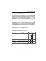
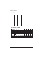
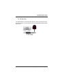
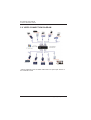
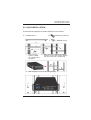
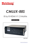
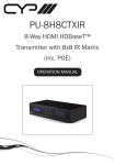
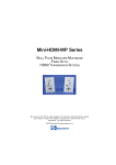
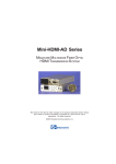
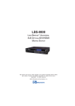
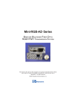
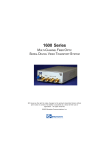
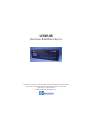
USW-88
UNIVERSAL 8X8 MATRIX SWITCH
BCI reserves the right to make changes to the products described herein without
prior notice or consent. No liability is assumed as a result of their use or
application. All rights reserved.
©2008 Broadata Communications, Inc.
BCI USW-88 User’s Manual
Universal 8x8 Matrix Switch
SAFETY INSTRUCTIONS AND
COMPLIANCE DECLARATIONS
PLEASE OBSERVE THE FOLLOWING SAFETY
PRECAUTIONS AS OUR PRODUCTS CONTAIN
CLASS I LASER PRODUCTS
WARNING
Do not disconnect the fiber optic connector while the unit is powered
up. Exposure to laser radiation is possible when the laser fiber optic
connector is disconnected while the unit is powered up.
Although the fiber optic connectors in this product emit only Class 1
energy that is below the levels considered to be hazardous, one should
never stare directly into a fiber optic connector or an unconnected fiber
end unless one can be certain that no exposure to laser energy could
occur.
CAUTION
This manual is intended for use by trained service personnel. The use
of controls, making adjustments, or performing operations other than
those specified may result in hazardous radiation exposure.
The following label or equivalent is located on the surface of laser products.
This label indicates that the product is classified as a CLASS 1 LASER
PRODUCT.
SURGE PROTECTION DEVICE RECOMMENDED
This product contains sensitive electrical components that may be
damaged by electrical spikes, surges, electric shock, lightning strikes,
etc. Use of surge protection systems is highly recommended in order
to protect and extend the life of your equipment.
Broadata Technical Support, [email protected]
3
BCI USW-88 User’s Manual
Universal 8x8 Matrix Switch
TABLE OF CONTENTS
1.0
2.0
3.0
3.1
3.2
3.3
4.0
4.1
4.2
5.0
6.0
7.0
8.0
8.1
8.2
9.0
4
PRODUCT DESCRIPTION .............................................5
OPERATION CONTROLS AND FUNCTIONS ...............6
REMOTE CONTROL ...................................................... 9
IR CUSTOM CODE ...................................................... 10
DISCRETE IR CODES ................................................. 10
IR RECEIVER ............................................................... 11
RS-232 PROTOCOL ..................................................... 12
PIN ASSIGNMENT ........................................................ 12
COMMANDS ................................................................. 13
VIDEO CONNECTION DIAGRAM ................................. 16
RACK INSTALLATION ................................................... 17
SPECIFICATIONS .......................................................... 18
SERVICE PROCEDURE ............................................... 20
REPLACEMENT POLICY ............................................. 20
RETURN AND REPAIR SERVICE ................................. 20
LIMITED WARRANTY .................................................... 21
Broadata Technical Support, (800) 214-0222
BCI USW-88 User’s Manual
Universal 8x8 Matrix Switch
1.0 PRODUCT DESCRIPTION
The USW-88 Series is a high performance Universal Matrix Switcher
System that provides 8x8 video switching for HDMI/DVI signals. Standard
versions of the USW-88 support all optical switching, or hybrid
optical/electrical switching for HDMI/DVI signals. When configured for
optical switching, only one multimode fiber is required per input or output
port. In addition, the distance between the switch and HDMI/DVI devices
can be up to 400m when connected by fiber cable.
The USW-88 is a true HDMI 1.3 switch, supporting jitter-free, high-quality
HDMI/DVI Display with 10-bit deep color digital video format and Dolby
or DTS featured digital audio format. It comes with three types of switching
control: manual control panel, PC based control software through standard
RS-232/422, or remote IR control.
The USW-88 comes in a 3-RU packaging design.
The USW-88 has the following configurations:
Model
Description
USW-88DVI
8x8 Universal Switch, DVI
USW-88HDMI
8x8 Universal Switch, HDMI
USW-88FOP
8x8 Universal Switch, Optical
USW-44D44F
8x8 Universal Switch, 4-DVI, 4-Optical
I/O Configuration
DVI 8
HDMI
8x8 Universal Switch, 4-HDMI, 4-Optical
DVI
8
8
HDMI
8x8
Optical
USW-88HDMI
8
8x8
8
8
Optical
8x8
4
DVI
Optical 4
4
4
DVI
Optical
8x8
HDMI 4
Optical 4
4
4
HDMI
Optical
8x8
Broadata Technical Support, [email protected]
5
BCI USW-88 User’s Manual
Universal 8x8 Matrix Switch
2.0 OPERATION CONTROLS AND FUNCTIONS
Front Panel
USW - 88
UNIVERSAL 8 x 8 SWITCH
OUT
IN
A
B
1
2
EDID
LOCK
C
3
D
4
E
5
F
6
DISPLAY MONITOR
G
7
H
8
FUNCTIONS
POWER
1
2
3
4
CONFIRM
5
6
ALL OUT
7
RECORD
8
RESTORE
9
10
1. Display monitor: This monitor displays switch settings
information with each output and input selection.
2. IR sensor: For remote IR control.
3. POWER: Press this button to turn the system on. Once the
system turns on the LED will turn Green and when entering
Standby Mode it will turn Red.
4. EDID: There will be two selections shown on the Display Monitor:
1. TV mode and 2.Standard Mode, press the number key to
first select the desired input and then press one or two to select
the EDID mode. The LED will turn on when setting the EDID.
After the selection is made, press CONFIRM key to confirm.
TV Mode means the device will use display’s EDID. The factory
default setting is TV mode. When EDID is switched to a TV
Mode, the USW-88 will first detect the output source’s EDID
from A-D and then record it in the USW-88 unit, regardless of
the output sources from E-H. If the first detected output source
is DVI it will pass on to the next source, until the first HDMI is
detected. The detection priority is HDMI v1.3 > HDMI v1.2 >
DVI. In order to ensure all output is displayable output from E-H
must be of a lower standard than output from A-D.
6
Broadata Technical Support, (800) 214-0222
BCI USW-88 User’s Manual
Universal 8x8 Matrix Switch
Standard Mode means the device will use internal built-in EDID.
When EDID is on Standard Mode, the USW-88 will use the
built-in EDID. In this case, Video Supports is less than 1080p,
10 bits (max), and Audio Supports is PCM2.
5. LOCK: Press this button to lock all the functions and press it
again to release the lock. When LED turns green, the lock is
activated and when it turns red the key lock has been released.
6. CONFIRM: Press this button after each and every selection to
confirm the setting. If this button is not pressed after 20
seconds, the selection will be cancelled.
7. ALL OUT: Press this button to set all the outputs to display
with the same input. After pressing the ALL OUT button, press
an input number and then press CONFIRM to confirm the
selection.
8. RECORD: Press this button to choose your six pre-set settings.
First press the setting number, and when all the input/outputs
are being set, be sure to press RECORD to record it into the
system. The factory default settings are 1.12345678,
2.87654321, 3.11223344, 4.55667788, 5.11221122, 6.33443344.
9. RESTORE: Select this button in order to restore your six pre-set
settings, then press CONFIRM key to confirm your selection.
10. OUT A~H & IN 1~8: Press the output source selection button
in order to choose which input port corresponds to the desired
output port. First select your output port from A-H, wait 2
seconds, then choose the desired input port from ports 1-8,
pressing CONFIRM key will confirm your setting. Each output
selection only allows a single input setting each time.
Broadata Technical Support, [email protected]
7
BCI USW-88 User’s Manual
Universal 8x8 Matrix Switch
Rear Panel
8
POWER 100-240VAC
H
G
OUTPUTS
F
E
8
INPUTS
6
5
PWR
LINK
PWR
LINK
PWR
LINK
PWR
LINK
PWR
LINK
PWR
LINK
PWR
LINK
PWR
LINK
PWR
LINK
PWR
LINK
PWR
LINK
PWR
LINK
PWR
LINK
D
C
B
A
RS-232
RS-232
USB
(UPGRADE)
(CONTROL)
(PROGRAM)
3
4
4
POWER
1
7
PWR
LINK
2
3
2
PWR
LINK
PWR
LINK
1
FAN
IR RX
5
6
7
1. OUTPUT A~H: These slots are where you connect the video
display through HDMI, DVI or Optical connections.
2. RS-232 (UPGRADE): This slot is where you connect a D-sub 9
male pin connector cable to your host, in order to upgrade your
firmware.
3. RS-232 (CONTROL): This slot is where you connect a D-sub 9
female pin connector cable to your host so you can control
USW-88 switch settings.
4. USB (PROGRAM): This slot is where you connect a USB b -type
connector cable to your host for System Program firmware
downloading.
5. IR RX: This slot is where you can extend your IR receiver with
an IR extender cable that accepts only 38KHz.
6. INPUT 1~8: These slots are where you connect the video
sources through HDMI, DVI or Optical connections.
7. POWER: This LED will turn GREEN when power is on.
8. Power 95-240 VAC: This is the AC power entry and switch.
8
Broadata Technical Support, (800) 214-0222
BCI USW-88 User’s Manual
Universal 8x8 Matrix Switch
3.0 REMOTE CONTROL
Section 3.1 shows the IR code for the remote control. There are a total
of four dipswitches located at the rear bottom of the remote control.
When dipswitches are all set to ON (upper position), the remote control
is able to control all the outputs and inputs. For example, when output A
wishes to select input 5, first press 1, wait a second, then press 5, and
instantly output display A will show input source 5’s image.
For other settings please refer to Section 3.2. For example, when all the
dipswitches are set to OFF, this setting is for output A, so it can only
control input selections. When output A wishes to select input 3, pressing
3 will allow output display A to only show input source 3’s content. For
additional settings please refer to Section 3.2.
Broadata Technical Support, [email protected]
9
BCI USW-88 User’s Manual
Universal 8x8 Matrix Switch
3.1 IR Custom Code
No.
1
2
3
4
5
6
7
8
9
0
DATA
88
89
8A
8C
8D
8E
90
91
92
95
3.2 Discrete IR Codes
Select /
Dipswitch
Output A
Output B
Output C
Output D
Output E
Output F
Output G
Output H
10
Input
1
0cx88
0cx88
0cx88
0cx88
0cx88
0cx88
0cx88
0cx88
Input
2
0x89
0x89
0x89
0x89
0x89
0x89
0x89
0x89
Input
3
0x8A
0x8A
0x8A
0x8A
0x8A
0x8A
0x8A
0x8A
Input
4
0x8C
0x8C
0x8C
0x8C
0x8C
0x8C
0x8C
0x8C
Input
5
0x8D
0x8D
0x8D
0x8D
0x8D
0x8D
0x8D
0x8D
Input
6
0x8E
0x8E
0x8E
0x8E
0x8E
0x8E
0x8E
0x8E
Input
7
0x90
0x90
0x90
0x90
0x90
0x90
0x90
0x90
Input
8
0x91
0x91
0x91
0x91
0x91
0x91
0x91
0x91
Broadata Technical Support, (800) 214-0222
BCI USW-88 User’s Manual
Universal 8x8 Matrix Switch
3.3 IR Receiver
The USW-88 also comes with a IR extension receiver (see figure below).
Use this receiver, one can remote control the USW-88 at a designated
field of view.
Broadata Technical Support, [email protected]
11
BCI USW-88 User’s Manual
Universal 8x8 Matrix Switch
4.0 RS-232 PROTOCOL
4.1 Pin Assignment
USW-88
PIN
PIN
Assignment
1
NC
1
NC
2
Tx
2
Rx
3
Rx
3
Tx
4
NC
4
NC
5
GND
5
GND
6
NC
6
NC
7
NC
7
NC
8
NC
8
NC
9
NC
9
NC
Baud Rate:
Data Bit:
Parity:
Flow Control:
12
Assignment
Remote Control Console
9600 bps
8 bits
None
None
Broadata Technical Support, (800) 214-0222
BCI USW-88 User’s Manual
Universal 8x8 Matrix Switch
4.2 Commands
COMMAND
POWER 00
POWER 01
PORT 11
PORT 12
PORT 13
PORT 14
PORT 15
PORT 16
PORT 17
PORT 18
PORT 21
PORT 22
PORT 23
PORT 24
PORT 25
PORT 26
PORT 27
PORT 28
PORT 31
PORT 32
PORT 33
PORT 35
PORT 36
PORT 37
PORT 38
PORT 41
PORT 42
PORT 43
PORT 44
ACTION
Power Off (standby)
Power On
Output A select Input 1
Output A select Input 2
Output A select Input 3
Output A select Input 4
Output A select Input 5
Output A select Input 6
Output A select Input 7
Output A select Input 8
Output B select Input 1
Output B select Input 2
Output B select Input 3
Output B select Input 4
Output B select Input 5
Output B select Input 6
Output B select Input 7
Output B select Input 8
Output C select Input 1
Output C select Input 2
Output C select Input 4
Output C select Input 5
Output C select Input 6
Output C select Input 7
Output C select Input 8
Output D select Input 1
Output D select Input 2
Output D select Input 3
Output D select Input 4
Broadata Technical Support, [email protected]
13
BCI USW-88 User’s Manual
Universal 8x8 Matrix Switch
COMMAND
PORT 45
PORT 46
PORT 47
PORT 48
PORT 51
PORT 52
PORT 53
PORT 54
PORT 55
PORT 56
PORT 57
PORT 58
PORT 61
PORT 62
PORT 63
PORT 64
PORT 65
PORT 66
PORT 67
PORT 68
PORT 71
PORT 72
PORT 73
PORT 74
PORT 75
PORT 76
PORT 77
PORT 78
PORT 81
PORT 82
PORT 83
PORT 84
14
ACTION
Output D select Input 5
Output D select Input 6
Output D select Input 7
Output D select Input 8
Output E select Input 1
Output E select Input 2
Output E select Input 3
Output E select Input 4
Output E select Input 5
Output E select Input 6
Output E select Input 7
Output E select Input 8
Output F select Input 1
Output F select Input 2
Output F select Input 3
Output F select Input 4
Output F select Input 5
Output F select Input 6
Output F select Input 7
Output F select Input 8
Output G select Input 1
Output G select Input 2
Output G select Input 3
Output G select Input 4
Output G select Input 5
Output G select Input 6
Output G select Input 7
Output G select Input 8
Output H select Input 1
Output H select Input 2
Output H select Input 3
Output H select Input 4
Broadata Technical Support, (800) 214-0222
BCI USW-88 User’s Manual
Universal 8x8 Matrix Switch
COMMAND
PORT 85
PORT 86
PORT 87
PORT 88
ACTION
Output H select Input 5
Output H select Input 6
Output H select Input 7
Output H select Input 8
Broadata Technical Support, [email protected]
15
BCI USW-88 User’s Manual
Universal 8x8 Matrix Switch
5.0 VIDEO CONNECTION DIAGRAM
*Can be replaced by DVI or HDMI cable when non-optical port version of
the USW-88 is used.
16
Broadata Technical Support, (800) 214-0222
BCI USW-88 User’s Manual
Universal 8x8 Matrix Switch
6.0 RACK INSTALLATION
Use the following diagram to install USW-88 in a rack chassis.
A L-Shaped rail x 2
B
Mounting screws x 4
C
L-Shaped rail x 2
A
B
B
1.
Use mounting
screws to attach
the L-shape rail to
the frame
2.
Make sure the L-shaped rail and the
mounting screws are properly aligned,
with two screws per L-shaped rail
A
A
3.
USW-88
Slide the device on top of the L-shaped rails.
C
C
Broadata Technical Support, [email protected]
17
BCI USW-88 User’s Manual
Universal 8x8 Matrix Switch
7.0 SPECIFICATIONS
Matrix Switch
Array Size
8x8
EDID Control
Independent
HDMI/DVI Ports
Resolution
Up to 1080p@60Hz or
1920x1200@60Hz
Connector
DVI or HDMI Female Plugs
Protocol
EDID, DDC, and HDCP Capable
Fiber Ports
Fiber Type
Multimode
Connector
SC
Protocol
EDID, DDC, and HDCP Capable
Control
Manual
Panel Button
RS-232
DB-9, 9600 bit/sec
IR
20-60 KHz
18
Broadata Technical Support, (800) 214-0222
BCI USW-88 User’s Manual
Universal 8x8 Matrix Switch
Physical
Dimension (H x W x D)
5.2” x 17.3” x 14.0”
Power Level
95-240 VAC @ 260W
Operating Temperature
0 to +50oC
Humidity
0 to 95% RH,
non-condensing
Broadata Technical Support, [email protected]
19
BCI USW-88 User’s Manual
Universal 8x8 Matrix Switch
8.0 SERVICE PROCEDURE
8.1 Replacement Policy
Standard products found defective on arrival (DOA) will be
replaced, based on availability, within 24 to 48 hours anywhere
in the U.S. Please call Customer Service at 800-214-0222 for
information.
8.2 Return/Repair Service
The USW-88 System contains no user serviceable components.
If you have a problem with your unit, please contact the
Customer Service Department. To facilitate our return/repair
processing please contact Broadata Communications, Inc. to
obtain a Return Material Authorization (RMA). Please include
the following information:
•
•
•
•
Product model number
Serial Number
Complete description of problem
Hardware installation description
Broadata Communications, Inc.
2545 West 237th Street, Suite K
Torrance, CA 90505
1-800-214-0222
(310) 530-1416
(310) 530-5958 (Facsimile)
e-mail: [email protected]
Website: www.broadatacom.com
20
Broadata Technical Support, (800) 214-0222
BCI USW-88 User’s Manual
Universal 8x8 Matrix Switch
9.0 LIMITED WARRANTY
Broadata Communications, Inc. (BCI) warrants, for a period of one year
from date of shipment, each product sold shall be free from defects in
material and workmanship. BCI will correct, either by repair, or at BCI’s
election, by replacement, any said products that in our sole discretion
prove to be defective and are returned to the manufacturing location
within 30 days after such defect is ascertained. All warranties are limited
to defects arising under normal use and do not include malfunctions or
failure resulting from misuse, abuse, neglect, alterations, electrical power
problems, usage not in accordance with product instructions, improper
installation, or damage determined by BCI to have been caused by the
Buyer or repair made by a third party. Limited warranties granted on
products are to the initial customer end-user and are not transferable.
OUR LIABILITY UNDER THIS WARRANTY SHALL IN ANY CASE BE
LIMITED TO THE INVOICE VALUE OF THE PRODUCT SOLD AND BCI
SHALL NOT BE LIABLE TO ANYONE FOR CONSEQUENTIAL OR
INCIDENTAL DAMAGES ARISING FROM THE USE OF ITS PRODUCTS
OR THE SALE THEREOF. We make NO WARRANTY AS TO THE
MERCHANTABILITY OF ANY GOODS, OR THAT THEY ARE FIT FOR
ANY PARTICULAR PURPOSE OR END APPLICATION NOR DO WE
MAKE ANY WARRANTY, EXPRESSED OR IMPLIED OTHER THAN
AS STATED ABOVE.
Broadata Technical Support, [email protected]
21
BCI USW-88 User’s Manual
Universal 8x8 Matrix Switch
22
Broadata Technical Support, (800) 214-0222
Broadata Communications, Inc.
2545 West 237th Street, Suite K
Torrance, CA 90505
1-800-214-0222
(310) 530-1416
(310) 530-5958 (Facsimile)
e-mail: [email protected]
Website: www.broadatacom.com
60000-USW-88