1
Department of Computer Science and Engineering
The University of Texas at Arlington
Team: Team MASS
Project: Rocket Recovery System
Team Members:
Clinton Spivey
Heera Main
David Salvagnini
Olalekan Ajayi
Rocket Recovery System
Contents
Contents ........................................................................................................................................................ ii
List of Figures ............................................................................................................................................... vi
List of Tables ............................................................................................................................................... vii
Document Revision History........................................................................................................................ viii
1. - Introduction ............................................................................................................................................ 1
1.1 - Document Overview ......................................................................................................................... 1
1.2 - Project Scope and Overview ............................................................................................................. 1
1.3 - Definitions and Acronyms ................................................................................................................. 4
2. - Architecture Overview ............................................................................................................................ 5
2.1 - Overview ........................................................................................................................................... 5
2.2 - The Intelligent Rotating Base Station ............................................................................................... 6
2.3 - The Rocket Recovery System ............................................................................................................ 6
2.4 - IRBS Module Decomposition ............................................................................................................ 7
2.5 - RRM Module Decomposition .......................................................................................................... 13
3. - IRBS Data Input ..................................................................................................................................... 18
3.1 - Overview ......................................................................................................................................... 18
3.2 - User Input – Button State ............................................................................................................... 18
3.3 - Anemometer Input – Calibrate ....................................................................................................... 20
3.4 - Anemometer Input – Direction....................................................................................................... 21
3.5 - Anemometer Input – RPM .............................................................................................................. 22
3.6 - Accelerometer Input - Accelerometer Reading .............................................................................. 23
4. - IRBS User Interface ............................................................................................................................... 25
4.1 - Overview ......................................................................................................................................... 25
4.2 - Get Data - Get Processed State....................................................................................................... 25
4.3 - Display Output – Format Data ........................................................................................................ 26
4.4 - Display Output – Print..................................................................................................................... 27
5. - IRBS Data Processing............................................................................................................................. 31
5.1 - Overview ......................................................................................................................................... 31
5.2 - Verify Data – Verify Accelerometer ................................................................................................ 31
March 8, 2013
ii
Team Mass
Rocket Recovery System
5.3 - Verify Data – Verify Anemometer................................................................................................... 32
5.4 - Encapsulate Data – Encapsulate Wind Data ................................................................................... 32
5.5 - Process Data – Calculate Wind Speed ............................................................................................ 34
5.6 - Process Data – Calculate Wind Direction........................................................................................ 34
5.7 - Process Data – Table Lookup .......................................................................................................... 35
5.8 - Set Data – Set Wind Speed ............................................................................................................. 36
5.9 - Set Data – Set Wind Direction ........................................................................................................ 36
5.10 - Set Data – Set Flight Data ............................................................................................................. 37
6. - IRBS Hardware Interface ....................................................................................................................... 38
6.1 - Overview ......................................................................................................................................... 38
6.2 - Get Data – Get Wind Data .............................................................................................................. 38
6.3 - Hardware Processing – Rotate Pan Servo....................................................................................... 39
6.4 - Hardware Processing – Rotate Tilt Servo........................................................................................ 40
7. - IRBS Network ........................................................................................................................................ 41
7.1 - Overview ......................................................................................................................................... 41
7.2 - Get Data – Get Flight Data .............................................................................................................. 41
7.3 - Send/Receive – Pack Data............................................................................................................... 42
7.4 - Send/Receive – Unpack Data .......................................................................................................... 42
7.5 - Send/Receive – Send Flight Data .................................................................................................... 43
7.6 - Send/Receive – Set ACK .................................................................................................................. 43
8. - RRM Network ........................................................................................................................................ 45
8.1 - Overview ......................................................................................................................................... 45
8.2 - Send/Receive – Unpack .................................................................................................................. 45
8.3 - Send/Receive – Pack ....................................................................................................................... 46
8.4 - Send/Receive – Send ACK ............................................................................................................... 46
9. - RRM Data Input..................................................................................................................................... 48
9.1 - Overview ......................................................................................................................................... 48
9.2 - Accelerometer Input - Accelerometer Reading .............................................................................. 48
9.3 - Barometer Input - Barometer Reading ........................................................................................... 49
10. - RRM Data Processing .......................................................................................................................... 51
10.1 - Overview ....................................................................................................................................... 51
10.2 - Verify Data - Verify Accelerometer ............................................................................................... 51
March 8, 2013
iii
Team Mass
Rocket Recovery System
10.3 - Verify Data - Verify Barometer ..................................................................................................... 52
10.4 - Stabilization Processing - Offset Calculation................................................................................. 53
10.5 - Air Pressure Processing - Calculate Altitude ................................................................................. 54
10.6 - Air Pressure Processing - Target Interrupt.................................................................................... 55
11. - RRM Hardware Interface .................................................................................................................... 56
11.1 - Overview ....................................................................................................................................... 56
11.2 - Hardware Processing – Offset Fin Controller ............................................................................... 56
11.3 - Hardware Processing – Target Fin Controller ............................................................................... 57
12. - IRBS Design ......................................................................................................................................... 58
13. - IRBS Hardware Design......................................................................................................................... 61
14. - IRBS Hardware Components ............................................................................................................... 63
14.1 - Overview ....................................................................................................................................... 63
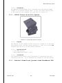
14.2 - HSR-1425CR Continuous Rotation Servo ...................................................................................... 63
14.3 - HS-645MG Servo Motor................................................................................................................ 64
14.4 - ADXL326 - 5V ready triple-axis accelerometer (+-16g analog out)............................................... 65
14.5 - DDT500 Direct Drive Tilt System ................................................................................................... 66
14.6 - Adafruit Perma-Proto Quarter-sized Breadboard PCB ................................................................. 66
15. - Launch Control Box Design ................................................................................................................. 68
16. - Launch Control Box Hardware Design ................................................................................................ 72
17. - Launch Control Box Hardware Components ...................................................................................... 74
17.1 - Overview ....................................................................................................................................... 74
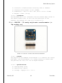
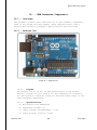
17.2 - Arduino Mega ............................................................................................................................... 74
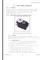
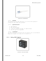
17.3 - Davis Anemometer, Standard (#7911) ......................................................................................... 75
17.4 - Rocker Switch – SPST .................................................................................................................... 76
17.5 - Toggle Switch and Cover - Illuminated (Red) ................................................................................ 76
17.6 - Concave Button – Red................................................................................................................... 77
17.7 - RGB backlight positive LCD 16x2................................................................................................... 78
17.8 - LED Indicators ............................................................................................................................... 78
17.9 - Relay SPDT Sealed ......................................................................................................................... 79
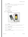
17.10 - Battery Holder............................................................................................................................. 80
17.11 - 9 Volt Battery .............................................................................................................................. 81
18. - RRM Hardware Design ........................................................................................................................ 82
March 8, 2013
iv
Team Mass
Rocket Recovery System
19. - RRM Hardware Components .............................................................................................................. 84
19.1 - Overview ....................................................................................................................................... 84
19.2 - Arduino Uno .................................................................................................................................. 84
19.3 - ADXL326 - 5V ready triple-axis accelerometer (+-16g analog out)............................................... 85
19.4 - BMP085 Barometric Pressure/Temperature/Altitude Sensor- 5V ready ..................................... 86
19.5 - HS-645MG Servo Motor................................................................................................................ 87
19.6 - Battery Holder............................................................................................................................... 88
19.7 - 9 Volt Battery ................................................................................................................................ 89
20. - SD-12 Rocket Design ........................................................................................................................... 90
21. - SD-12 Components ............................................................................................................................. 92
22. - Traceability Matrices .......................................................................................................................... 93
23. - Quality Assurance ............................................................................................................................... 95
23.1 - Test Plans and Procedures ............................................................................................................ 95
23.2 - Module/Unit Test.......................................................................................................................... 95
24. - Acceptance Plan .................................................................................................................................. 98
24.1 - Overview ....................................................................................................................................... 98
24.2 - Packaging and Installation ............................................................................................................ 98
24.3 - Acceptance Criteria ....................................................................................................................... 99
March 8, 2013
v
Team Mass
Rocket Recovery System
List of Figures
Figure 1-1 - Rocket Recovery System ............................................................................................................ 2
Figure 1-2-Rocket Recovery System ............................................................................................................. 3
Figure 5-2-1- Architecture Overview ............................................................................................................ 5
Figure 2-2- IRBS Module Chart...................................................................................................................... 8
Figure 2-3 - RRM MODULE CHART .............................................................................................................. 14
Figure 3-1- Data Input Diagram .................................................................................................................. 18
Figure 7-1 IRBS Data Processing Diagram ................................................................................................... 31
Figure 6-1- hardware interface Diagram .................................................................................................... 38
Figure 7-1- network Diagram ...................................................................................................................... 41
Figure 8-1- RRM network Diagram ............................................................................................................. 45
Figure 9-1 - RRM Data Input Diagram ......................................................................................................... 48
Figure 12-1 RRM Data Processing Diagram ................................................................................................ 51
Figure 11-1 – RRM hardware interface Diagram ........................................................................................ 56
Figure 12-1 - IRBS Design Profile view ........................................................................................................ 58
Figure 12-2 - IRBS Design Under Pad View #1 ............................................................................................ 59
Figure 12-3 - IRBS Design Under Pad View #2 ............................................................................................ 59
Figure 12-4 - IRBS Design Above View ........................................................................................................ 60
Figure 13-1- IRBS Bread Board Layout ........................................................................................................ 61
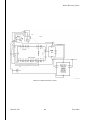
Figure 13-2- IRBS schematic Layout ............................................................................................................ 62
Figure 14-1- HSR-1425CR Continuous Rotation Servo ................................................................................ 63
Figure 14-2 - HS-645MG Servo Motor ........................................................................................................ 64
Figure 14-3 - ADXL326 - 5V ready triple-axis accelerometer ...................................................................... 65
Figure 14-4 - DDT500 Direct Drive Tilt System............................................................................................ 66
Figure 14-5- Adafruit Perma-Proto Quarter-sized Breadboard PCB ........................................................... 67
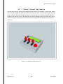
Figure 15-1-Launch Control Box View #1 .................................................................................................... 68
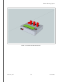
Figure 15-2-Launch Control Box View #2 .................................................................................................... 69
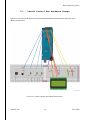
Figure 15-3-Launch Control Box View #3 .................................................................................................... 70
Figure 15-4-Launch Control Box View #4 .................................................................................................... 71
Figure 17-10 - Battery Holder ..................................................................................................................... 80
Figure 17-2 - 9 Volt Battery ......................................................................................................................... 81
Figure 19-1 - Arduino Uno .......................................................................................................................... 84
Figure 19-2- ADXL326 - 5V ready triple-axis accelerometer ....................................................................... 85
Figure 19-3- BMP085 Barometric Pressure/Temperature/Altitude Sensor ............................................... 86
Figure 19-4 - HS-645MG Servo Motor ........................................................................................................ 87
Figure 19-50 - Battery Holder ..................................................................................................................... 88
Figure 19-6 - 9 Volt Battery ......................................................................................................................... 89
March 8, 2013
vi
Team Mass
Rocket Recovery System
List of Tables
Table 1.1- Definitions and Acronyms ............................................................................................................ 4
Table 2.1 - IRBS Module Data Flows ............................................................................................................. 9
Table 2.2- IRBS Producer Consumer Matrix................................................................................................ 10
Table 2.3- RRM MODULE DATA FLOWS ...................................................................................................... 15
Table 2.4- RRM Producer Consumer Matrix ............................................................................................... 16
March 8, 2013
vii
Team Mass
Rocket Recovery System
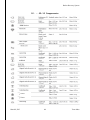
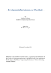
Document Revision History
Revision Revision
Number Date
0.1
0.2
0.3
1.0
2.0
2/9/2013
2/26/2013
2/26/2013
2/26/2013
2/26/2013
March 8, 2013
Description
Rationale
Created Document
Merged
Final edits
Submitted informal review
Submitted final edition
viii
First version of the DDS
Merged each branch of the document
Final QA inspection
Team Mass
Rocket Recovery System
1. - Introduction
1.1 - Document Overview
The Detailed Design Document will provide a low level description of the Rocket Recovery System.
The document will provide information sufficient enough to begin a detailed design of the systems. The
system will be divided into modules that provide the detail and functionality of each sub system. The
modules will include information about inputs, outputs, data required, processing, and the pseudo code.
The document will also include relationship mapping between various requirements and modules,
quality assurance and testing considerations, and all specific details and design of all specific hardware
parts.
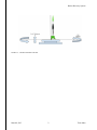
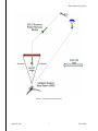
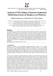
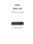
1.2 - Project Scope and Overview
The Rocket Recovery System’s central purpose is to launch a low powered model rocket and land it
near the area where it was launched from. The Rocket Recovery System (RRS) has three components;
The Intelligent Rotating Base Station (IRBS), The SD-12 Rocket, and the Rocket Recovery Module (RRM).
The Intelligent Rotating Base Station is a launch pad that gathers information about the wind speed and
direction using an attached anemometer. The IRBS will then compensate for the wind by rotating and
tilting the launch pad in the appropriate direction. The IRBS will pass the wind data to the SD-12 Rocket
equipped with the Rocket Recovery Module before launch. After the launch of the SD-12 rocket, the
RRM will make real time calculations, using the IRBS data, to direct the rocket to a specified location.
After the engine burn phase, a parachute will be deployed, and the SD-12 will float back to the
coordinates where it was launched. The system will have an attached control launch box that the user
interacts with the system with. This launch box is attached to the IRBS via a bus line.
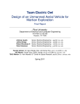
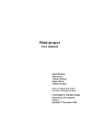
The Rocket Recovery System will have three modes. These modes include: Standby Mode,
Preparation Mode, and Launch Mode. The Standby mode will allow the user to attach the SD-12 rocket
to the IRBS and make necessary adjustments. In this mode no data is being collected or used. The
Preparation Mode will start to collect wind data from the attached anemometer, and make the
adjustments to the IRBS. The Launch Mode will have the IRBS stop making adjustments, and start
transmitting the aggregated wind data to the RRM. Once the SD-12 rocket receives all the information,
the rocket is ready to launch.
March 8, 2013
1
Team Mass
Rocket Recovery System
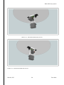
FIGURE 1-1 - ROCKET RECOVERY SYSTEM
March 8, 2013
2
Team Mass
Rocket Recovery System
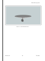
FIGURE 1-2-ROCKET RECOVERY SYSTEM
March 8, 2013
3
Team Mass
Rocket Recovery System
1.3 - Definitions and Acronyms
Term
RRM
IRBS
SD-12
LCD
LED
OS
Definition
Rocket Recovery Module
Intelligent Rotating Base Station
The actual rocket that will have the Rocket Recovery Module inside of it
Liquid Crystal Display
Light Emitting Diode
Operating System
TABLE 1.1- DEFINITIONS AND ACRONYMS
March 8, 2013
4
Team Mass
Rocket Recovery System
2. - Architecture Overview
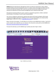
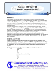
FIGURE 5-2-1- ARCHITECTURE OVERVIEW
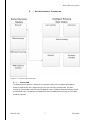
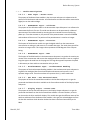
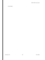
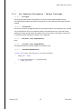
2.1 - Overview
The Rocket Recovery System is divided in to 2 separate systems. The intelligent Rotating Base
Station is dived further into 5 separate layers; The User Interface, The Data Input, The Data
Processing, The Hardware Interface, and The Network Layer. The Rocket Recovery Module is dived
into 4 distinct layers; The Network, The RRM Data Input, The RRM Data Processing, and The RRM
Hardware Interface.
March 8, 2013
5
Team Mass
Rocket Recovery System
2.2 - The Intelligent Rotating Base Station
2.2.1 - User Interface
The IRBS User Interface Layer is responsible for allowing the user to visually interact with the
system. This layer allows the user to see what user input has been entered and what data has
been collected and processed. This layer consists of two subsystems; Get Data and Display
Output.
2.2.2 - Data Input
The IRBS Data Input Layer is responsible for handling the user input, the anemometer input, and
the accelerometer. The IRBS Data Input layer consists of three subsystems, the User Input, the
Anemometer Input, and the Accelerometer Input.
2.2.3 - Data Processing
The IRBS Data Processing Layer’s purpose is to emphasize modularity in the design structure of
the system. All processing of data will be encapsulated within this layer and the resulting
comprehendible data will be made available to the respective systems, the hardware layer, the
user interface layer, and the network layer.
2.2.4 - Hardware Interface
The IRBS Hardware Layer is responsible for obtaining the data that will be used by the servo to
rotate at a specific angle depending on the speed of the wind.
2.2.5 - Network
The IRBS Network layer is the last layer of the IRBS system and retrieves data from the IRBS Data
Processing Layer. The layer either de-multiplexes or multiplexes the data with the RRM Network
layer. IRBS Network layer consists of Send/Receive Subsystem and Get Data Subsystem.
2.3 - The Rocket Recovery System
2.3.1 - Network
The RRM Network Layer is the first layer of the RRM system, and it connects RRM system with
the IRBS system. The layer either multiplexes or de-multiplexes the data with the IRBS Network
layer. RRM Network layer consists of Send Data Subsystem and Receive Data Subsystem.
2.3.2 - RRM Data Input
The RRM Data Input Layer is responsible for handling the input data from the accelerometer,
barometer, and the processed data from Network Layer. The RRM Data Input layer consists of
three subsystems; The Accelerometer Input, The Barometer input, and the IRBS Processed
Input.
2.3.3 - RRM Data Processing
The purpose of the RRM Data Processing Layer is to emphasize modularity in the design
structure of the system. All processing of data will be encapsulated within this layer and the
resulting comprehendible data will be made available to the hardware layer.
March 8, 2013
6
Team Mass
Rocket Recovery System
2.3.4 - RRM Hardware Interface
The RRM Hardware Layer is responsible for obtaining the air pressure and acceleration data
from the RRM Data Process layer in determine the stability of the rocket and the servo opening
for the landing.
2.4 - IRBS Module Decomposition
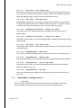
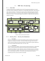
2.4.1 - Overview
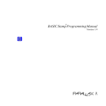
The main purpose of DDS was to break down each sub system into modules. This section
contains the high level definition of each module that we have in the IRBS system.
March 8, 2013
7
Team Mass
Rocket Recovery System
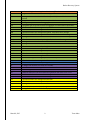
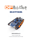
2.4.2 - Module Chart
FIGURE 2-2- IRBS MODULE CHART
Data Element
D1
D2
D3
D4
D5
March 8, 2013
Data Description
The change in buttons current state.
An integer that contains the wind direction (0 to 360) data.
A long that contains the wind speed in mph.
Integer values that contain the orientation values for x, y, z.
A String that contains the confirmation message that the anemometer has been
calibrated.
8
Team Mass
Rocket Recovery System
D6
DP1
DP2
DP3
DP4
DP5
DP6
DP7
DP8
DP9
DP10
DP11
DP12
DP13
DP14
DP15
DP16
DP17
DP18
DP19
H1
H2
N1
N2
N3
N4
N5
N6
UI1
UI2
UI3
UI4
UI5
New low and high values using the Arduino’s map() function.
Integer values that contain the values for x, y, z and has been error checked.
An integer that contains the wind direction (0 to 360) data and has been error
checked.
A long that contains the wind speed in mph and has been error checked.
An integer array that contains the aggregate of collected wind direction data.
A Long data type array that contains the aggregate of collected wind speed data.
A float that contains the average wind speed.
A float that contains the average wind direction.
A float that contains the average wind speed. Final value set for storage
A float that contains the average wind direction. Final value set for storage
An integer that contains the rocket turn altitude. Final value set for storage
A float that contains the launch pad angle. Final value set for storage
An integer that contains the rocket turn altitude.
An integer that contains the rocket turn altitude.
A float that contains the launch pad angle.
A float that contains the average wind direction.
A float that contains the average wind speed.
A float that contains the launch pad angle.
A float that contains the average wind direction.
A Boolean data type containing the pad over tilt safety function.
A float that contains the average wind direction.
A float that contains the launch pad angle
An integer that contains the rocket turn altitude.
A struct that contains an integer that contains the rocket turn altitude.
A acknowledgement struct.
A boolean value from the struct determining whether the data is sent or not.
A boolean value from the struct determining whether the data is sent or not.
A boolean value from the struct determining whether the data is sent or not.
A float that contains the average wind direction.
A float that contains the average wind speed.
An integer value that contains the altitude
A float value that contains the pad angle
A string of all the formatted data for display.
TABLE 2.1 - IRBS MODULE DATA FLOWS
March 8, 2013
9
Team Mass
Rocket Recovery System
Consumer
Hardware Processing - Rotate Tilt Servo
Hardware Processing - Rotate Pan Servo
Send Receive - ACK
Get Data - Get Wind Data
D1
D6
D5
D2
D3
D4
UI1,UI2,UI3,UI4
UI5
DP1
DP2,DP3
DP4 DP5
DP6 DP8
DP7
DP9
DP10,DP11
DP16
DP15
DP13,DP14
DP18
DP17
DP12
N1
N2
N5 N4
N3
N6
H1 H2
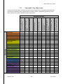
TABLE 2.2- IRBS PRODUCER CONSUMER MATRIX
March 8, 2013
From RRM
Send Receive - Send Flight Data
Send Receive - Pack Data
Send Receive - Unpack Data
Get Data - Get Flight Data
Set Data - Set Flight Data
Set Data - Set Wind Direction
Set Data - Set Wind Speed
Process Data - Table Lookup
Process Data - Calculate Wind Speed
Process Data - Calculate Wind Direction
Encapsulate Data - Encapsulate Wind Data
Verify Data - Verify Anemometer
Display Output - Print
Verify Data - Verify Accelerometer
Display Output - Format Data
Get Data - Get Processed State
Anemometer Input - RPM
Accelerometer Input - Accelerometer Reading
Anemometer Input - Calibrate
Anemometer Input - Direction
User Input - Button State
Producer
User Input - Button State
Anemometer Input - Calibrate
Anemometer Input - Direction
Anemometer Input - RPM
Accelerometer Input - Accelerometer Reading
Get Data - Get Processed State
Display Output - Format Data
Display Output - Print
Verify Data - Verify Accelerometer
Verify Data - Verify Anemometer
Encapsulate Data - Encapsulate Wind Data
D19
Process Data - Calculate Wind Speed
Process Data - Calculate Wind Direction
Process Data - Table Lookup
Set Data - Set Wind Speed
Set Data - Set Wind Direction
Set Data - Set Flight Data
Get Data - Get Flight Data
Send Receive - Pack Data
Send Receive - Unpack Data
Send Receive - Send Flight Data
From RRM
Send Receive - ACK
Get Data - Get Wind Data
Hardware Processing - Rotate Pan Servo
Hardware Processing - Rotate Tilt Servo
10
Team Mass
Rocket Recovery System
2.4.3 - Module Descriptions
2.4.3.1 - User Input – Button State
The purpose of the Button State module in the User Input subsystem is to determine the
position of all the buttons and switches. All of the buttons and switches will be connected to
digital pins on the Arduino Mega.
2.4.3.2 - Anemometer Input – Calibrate
The purpose of the calibrate module in the Anemometer Input Subsystem is to calibrate the
anemometer before its first use. The wind vane direction can be permanently calibrated
upon startup of the Arduino board by orienting the vane towards the true north during
power up. From that moment on, the position of the potentiometer is stored in EEPROM
and readouts will be correct. The position of the potentiometer is saved as an integer.
2.4.3.3 - Anemometer Input – Direction
The Purpose of the direction module is to get the digital value from the Anemometer
connected to an analog pin and convert it to a usable data type. The initial data type will be
stored as an integer value. This integer value represents the 360 degrees of the compass
baring.
2.4.3.4 - Anemometer Input – RPM
The Purpose of the RPM module in the Anemometer subsystem is to gather the rotation per
minute of the anemometer and convert the raw digital data and convert it into an unsigned
long data type to be used later in the program. The long data type will represent the speed
in Kilometers per hour and then converted to miles per hour.
2.4.3.5 - Accelerometer Input - Accelerometer Reading
The purpose of the Accelerometer Reading module in the Accelerometer Input subsystem is
to gather the raw digital data from the attached accelerometer and convert it into 3
separate integer value. These three values will represent the X,Y, and Z coordinates.
2.4.3.6 - Get Data – Get Processed State
The purpose of the Get Processed State module in the Get Data subsystem is to get the
processed wind data and make it available to the Format Data module of the Display Output
Subsystem.
2.4.3.7 - Display Output – Format Data
The purpose of the Format Data subsystem in the Display Output subsystem is to get the
processed wind data from the Get Processed State module. It formats the data, so that it
can be send to the Print module for display. This module also gets the different states of the
switches and button from the Button State module. It also gets the acknowledgement from
the Set ACK module to check whether the data has been transferred successfully to the
RRM.
March 8, 2013
11
Team Mass
Rocket Recovery System
2.4.3.8 - Display Output - Print
The purpose of the Print module is to display the relevant information to the user. It displays
the different modes of the system through the LCD and LEDs, and it also displays the wind
speed, wind direction, altitude, and pad angle on an LCD.
2.4.3.9 - Verify Data – Verify Accelerometer
Data that is received from the Accelerometer Reading module in the Data Input layer will be
brought to this module for verification. Verification includes filtering out extreme outliers.
Extreme outliers are defined as values that exceed the realistic value for a given calculation,
in this case any orientation value where value < 0 or value > 360.
2.4.3.10 - Verify Data – Verify Anemometer
Data that is received from the RPM and Direction module in the Data Input layer will be
brought to this module for verification. Verification includes filtering out extreme outliers.
Extreme outliers are defines as values that exceed the realistic value for a given calculation,
in this case wind speed values > 20 or < 0, or direction < 0 or > 360 degrees.
2.4.3.11 - Encapsulate Data – Encapsulate Wind Data
Data that is received from the verify functions will be consolidated into two separate data
structures within this module. The flow of information from the verify functions is constant
for the duration of the preparation mode. Once the preparation mode is complete the
function will call the calculate wind and speed functions for further processing.
2.4.3.12 - Process Data – Calculate Wind Speed
The sole purpose of this function is to average each element of the array of wind speeds.
2.4.3.13 - Process Data – Calculate Wind Direction
The sole purpose of this function is to average each element of the array of wind directions.
2.4.3.14 - Process Data – Table Lookup
Our system is going to have a set of tables that list all the possible settings for a given wind
speed and direction. These settings include the pad angle and the rockets turn altitude.
Once the averages are calculated this module will conduct the lookup for these two values
and send that data to the Set Flight Data module within the Set Data subsystem.
2.4.3.15 - Set Data – Set Wind Speed
This function is simply the interface into the data that the Data Processing layer computes
for all other layers. It specifically contains the accessor functions for the average wind
speed. Doing this ensures encapsulation of data.
2.4.3.16 - Set Data – Set Wind Direction
This function is simply the interface into the data that the Data Processing layer computes
for all other layers. It specifically contains the accessor functions for the average wind
direction. Doing this ensures encapsulation of data.
March 8, 2013
12
Team Mass
Rocket Recovery System
2.4.3.17 - Set Data – Set Flight Data
This function is simply the interface into the data that the Data Processing layer computes
for all other layers. It specifically contains the accessor functions for the SD-12 Rocket turn
altitude and IRBS pad angle. Doing this ensures encapsulation of data.
2.4.3.18 - Get Data – Get Wind Data
Get Wind Data module serves as a temporary storage for the wind data received from the
Set Flight Data and Set Wind Direction modules of the Set Data Layer. These data received
are used for the tilting and rotating the servo in a specific direction and angle.
2.4.3.19 - Hardware Processing – Rotate Pan Servo
The module will use the average wind direction to regulate and rotate the servo to a
required angle.
2.4.3.20 - Hardware Processing – Rotate Tilt Servo
The purpose of the module is to use the wind speed data to regulate and rotate the servo to
a specific angle.
2.4.3.21 - Get Data – Get Flight Data
The Get Flight Data module is responsible for using the altitude to turn the angle that will be
used by the rocket.
2.4.3.22 - Send/Receive – Pack Data
The module breaks down the flight data into packets that will be sent to the RRM system
2.4.3.23 - Send/Receive – Unpack Data
The Unpack Data module extracts the signal in Boolean form and stores in Set ACK module
2.4.3.24 - Send/Receive – Send Flight Data
The purpose of the module is to store the packet data and the Boolean value to confirm
whether the data is sent or not.
2.4.3.25 - Send/Receive – Set ACK
The Set ACK module stores the Boolean value that gives the result to whether the data is
sent or not.
2.5 - RRM Module Decomposition
2.5.1 - Overview
The main purpose of DDS was to break down each sub system into modules. This section
contains the high level definition of each module that we have in the RRM system.
March 8, 2013
13
Team Mass
Rocket Recovery System
2.5.2 - Module Chart
FIGURE 2-3 - RRM MODULE CHART
March 8, 2013
14
Team Mass
Rocket Recovery System
Data Element
N7
N8
N9
N10
N3
RD1
RD2
RDP1
RDP2
RDP3
RDP4
RDP5
Data Description
A struct that contains an integer that contains the rocket turn altitude.
An integer that contains the rocket turn altitude.
A boolean value that determine whether the data is sent or not
A struct containing a the boolean value
A struct containing a the boolean value
Integer values that contain the orientation values for x, y, z in degrees.
An integer value that contains the air pressure in hPa.
An integer value that contains the air pressure that has been error
checked.
An integer that contains the current altitude
Integer values that contains the orientation values for x, y, z and has
been error checked.
Integer values that contain the desired orientation values for x, y, z.
This is the minimum orientation that the rocket should be flying.
A boolean value that will trigger the turn when the target altitude is
hit.
TABLE 2.3- RRM MODULE DATA FLOWS
March 8, 2013
15
Team Mass
Rocket Recovery System
Consumer
Hardware Processing - Target Fin Controller
Hardware Processing - Offset Fin Controller
Air Pressure Processing - Target Interrupt
Air Pressure Processing- Calculate Altitude
Stabilization Processing - Offset Calculation
Verify Data - Verify Barometer
Verify Data - Verify Accelerometer
Barometer Input - Barometer Reading
Accelerometer Input - Accelerometer Reading
To IRBS
Send Receive - Send ACK
Send Receive - Unpack Data
Send Receive - Pack Data
From IRBS
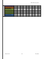
Producer
From IRBS
Send Receive - Pack Data
Send Receive - Unpack Data
Send Receive - Send ACK
To IRBS
Accelerometer Input - Accelerometer Reading
Barometer Input - Barometer Reading
Verify Data - Verify Accelerometer
Verify Data - Verify Barometer
Stabilization Processing - Offset Calculation
Air Pressure Processing- Calculate Altitude
Air Pressure Processing - Target Interrupt
Hardware Processing - Offset Fin Controller
Hardware Processing - Target Fin Controller
N7
N10
N9
N8
N3
RD1
RD2
RDP3
RDP1
RDP4
RDP2
RDP5
TABLE 2.4- RRM PRODUCER CONSUMER MATRIX
2.5.3 - Module Descriptions
2.5.3.1 - Send/Receive – Pack Data
The module receives the packet data and stores it in a structure to be packed and
acknowledged.
2.5.3.2 - Send/Receive – Unpack Data
The Pack module extracts the packet in Boolean form to determine if the data is sent or not.
2.5.3.3 - Send/Receive – Send ACK
The Send ACK module receives the Boolean and stores it as a structure object.
2.5.3.4 - Accelerometer Input - Accelerometer Reading
The purpose of the Accelerometer Reading module in the Accelerometer Input subsystem is
to gather the raw digital data from the attached accelerometer and convert it into 3
separate integer value. These three values will represent the X,Y, and Z coordinates.
March 8, 2013
16
Team Mass
Rocket Recovery System
2.5.3.5 - Barometer Input - Barometer Reading
The purpose of the Barometer Reading module in the Barometer Input subsystem is to
gather the raw digital data from the BMP085 Barometric Pressure Sensor and convert it into
an integer value representing the current air pressure.
2.5.3.6 - Verify Data – Verify Accelerometer
Data that is received from the Accelerometer Reading module in the Data Input layer will be
brought to this module for verification. Verification includes filtering out extreme outliers.
Extreme outliers are defined as values that exceed the realistic value for a given calculation,
in this case any orientation value where value < 0 or value > 360.
2.5.3.7 - Verify Data – Verify Barometer
Data that is received from the Barometer Reading module in the Data Input layer will be
brought to this module for verification. Verification includes filtering out extreme outliers.
Extreme outliers are defined as values that exceed the realistic value for a given calculation,
in this case any orientation value where value < 300 or value > 1100.
2.5.3.8 - Stabilization Processing – Offset Calculation
The stabilization of the rocket is happening during the rocket accent until the rocket turns.
Given that the F50-6 rocket motor burns for 1.37 seconds this module will be stabilizing the
rocket for about a second, which is roughly when it will reach its target turn altitude.
Stabilization is defined as correcting the rockets orientation on accent. Corrections may
have to be made if the rocket changes its roll orientation. This is critical given that the turn
angle and direction of the rocket are fixed.
2.5.3.9 - Air pressure Processing - Calculate Altitude
Given that the SD-12 rocket must know its current altitude so that we know when to turn
into the wind we are required to do some conversions from air pressure, hPa, feet above
the IRBS. This is required because the turn altitude as prescribed by the lookup tables in the
IRBS Data Processing Layer were calculated using feet above the IRBS.
2.5.3.1 - Air pressure Processing - Target Interrupt
The Target Interrupt module’s only purpose is to listen to the altitude readings from the
Calculate Altitude module and send the command to turn the rocket when the target
altitude is reached.
2.5.3.2 - Hardware Processing – Offset Fin Controller
The module will use the integer x,y,and z coordinates to offset the rocket fins for proper
stability.
2.5.3.3 - Hardware Processing – Target Fin Controller
The purpose of the module is to access the coordinate values needed by the fin and triggers
the turning of the servo using the Boolean value
March 8, 2013
17
Team Mass
Rocket Recovery System
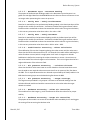
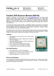
3. - IRBS Data Input
3.1 - Overview
The IRBS Data Input Layer is used for handling the user input, the anemometer input, and the
accelerometer input. The layer’s primary reasonability is converting the raw digital signal into
certain usable data types. The conversion of the data will take place in the Arduino Mega. The IRBS
Data Input layer consists of three subsystems, the User Input, the Anemometer Input, and the
Accelerometer Input.
Data Input
User input
Button Press
Button State
D1
Anemometer Input
D5
Calibrate
D6
Anemometer
RPM
Direction
Adjusted Anemometer
D2
D3
Accelerometer Input
Accelerometer
Accelerometer Reading
D4
FIGURE 3-1- DATA INPUT DIAGRAM
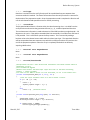
3.2 - User Input – Button State
3.2.1 - Prologue
The purpose of the Button State module in the User Input subsystem is to determine the
position of all the buttons and switches. All of the buttons and switches will be connected to
digital pins on the Arduino Mega.
March 8, 2013
18
Team Mass
Rocket Recovery System
3.2.2 - Interfaces
All the buttons and switches will interface though the digital pins on the Arduino Mega.
3.2.3 - External Data Dependencies
The button state module is dependent on the actual button presses and switch movement from
the user of the system. It is also dependent on the encapsulate data module to get the pad
angle data.
3.2.4 - Internal Data Dependencies
The module is dependent on the Boolean value from the encapsulate data module.
3.2.5 - Process/Pseudocode
const
const
const
const
int
int
int
int
switch1 = 2;
switch2 = 3;
switch3 = 4;
launchButton = 5;
// variables will change:
int switchState1 = 0;
int switchState2 = 0;
int switchState3 = 0;
int launchButtonState = 0;
// the number of the first switch pin
// the number of the second switch pin
// the number of the third switch pin
// the number of the launch button pin
// variable for reading the switch1 status
// variable for reading the switch2 status
// variable for reading the switch3 status
// variable for reading the launchButton status
void setup() {
// initialize the pushbutton pin as an input:
pinMode(switch1, INPUT);
pinMode(switch2, INPUT);
pinMode(switch3, INPUT);
pinMode(launchButton, INPUT);
}
void loop(){
// read the state of the pushbutton value:
switchState1 = digitalRead(switch1);
switchState2 = digitalRead(switch2);
switchState3 = digitalRead(switch3);
launchButtonState = digitalRead(launchButton);
// check if the pushbutton is pressed if it is, the buttonState is HIGH:
if ((switchState1 == HIGH) && (switchState2 == LOW) && (switchState2 ==LOW))
{
//User is in setup mode
}
if ((switchState1 == HIGH) && (switchState2 == HIGH) && (switchState2 ==LOW))
{
//User is in preperation mode
//Wait 2 minutes to gather data
}
//if user waited two minutes
March 8, 2013
19
Team Mass
Rocket Recovery System
if ((switchState1 == HIGH) && (switchState2 == HIGH) && (switchState2 ==HIGH))
{
//User is in launch mode
//display count down
//After count down
if ((switchState1 == HIGH) && (switchState2 == HIGH) && (switchState2
==HIGH) && (launchButtonState == HIGH))
{
If (Object.getPadTilt==1)
{
//Launch Rocket
}
}
}
}
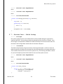
3.3 - Anemometer Input – Calibrate
3.3.1 - Prologue
The purpose of the calibrate module in the Anemometer Input Subsystem is to calibrate the
anemometer before its first use. The wind vane direction can be permanently calibrated upon
startup of the ARDUINO board by orienting the vane towards the true north during power
up. From that moment on, the position of the potentiometer is stored in EEPROM and readouts
will be correct. The position of the potentiometer is saved as an integer.
3.3.2 - Interfaces
The Davis Anemometer (#7911) interfaces with the Arduino Mega on one digital pin and one
analog pin. The Arduino Mega’s EEPROM (nonvolatile memory) is also accessed and the
potentiometer position is saved to the EEPORM.
3.3.3 - External Data Dependencies
The module is only dependent on the physical direction of the anemometer during power up.
3.3.4 - Internal Data Dependencies
The module will send data to both the format data module in the user interface layer as well as
the RPM module in the data input layer.
3.3.5 - Process/Pseudocode
#define PotPin (A0)
// define the input pin for the wind vane potentiometer
#define CalPin (A1)
// define the input pin to initiate direction calibration @
startup. Ground pin to calibrate
void calibrate () {
int PotValue = 0;
// variable to store the value coming from the
potentiometer
int DirCorr = 0;
// Correction on direction ( - 360 to + 360)
byte DirCorrB1 = 0;
// 2 bytes of DirCorr
byte DirCorrB2 = 0;
lcd.print("Now calibrating ...
");
delay (1000); //Wait 1 second
March 8, 2013
20
Team Mass
Rocket Recovery System
PotValue = analogRead(PotPin);
// read the value from the potentiometer
DirCorr = map(PotValue, 0, 1023, 359, 0);
lcd.setCursor(0, 1);
lcd.print("CAL value = ");
lcd.print(DirCorr, DEC);
lcd.print("
");
delay (2000); //Wait 2 seconds
DirCorrB1 = DirCorr / 255;
if (DirCorrB1 == 1)
{
DirCorrB1 = 255;
DirCorrB2 = DirCorr - 255 ;
}
else {
DirCorrB1 = DirCorr;
DirCorrB2 = 0;
}
EEPROM.write (1, DirCorrB1);
EEPROM.write (2, DirCorrB2);
wait:
lcd.setCursor(0, 1);
lcd.print("CAL OK ");
if ((analogRead(CalPin)<512)) goto wait;
lcd.setCursor(0, 1);
lcd.print("Now rebooting...
");
delay (1000);
setup ();
}
3.4 -
Anemometer Input – Direction
3.4.1 - Prologue
The Purpose of the direction module is to get the digital value from the Anemometer connected
to an analog pin and convert it to a usable data type. The initial data type will be stored as an
integer value. This integer value represents the 360 degrees of the compass baring.
3.4.2 - Interfaces
The Davis Anemometer (#7911) interfaces with an Arduino Mega analog pin for the wind
direction data.
3.4.3 - External Data Dependencies
The direction module is dependent on the actual external wind direction.
3.4.4 - Internal Data Dependencies
The direction module is not dependent on any internal data.
3.4.5 - Process/Pseudocode
int windDirection()
{
March 8, 2013
21
Team Mass
Rocket Recovery System
int Direction ; // Wind direction
int PotValue = analogRead(PotPin);
// read the value from the potmeter
Direction = map(PotValue, 0, 1023, 0, 359);
Direction = Direction + DirCorr + 3;
// Correct for offset & 5° precision
convert:
// Convert to 360°
if (Direction < 0)
{
Direction = Direction + 360;
goto convert;
}
if (Direction > 360)
{
Direction = Direction - 360;
goto convert;
}
if (Direction == 360) Direction = 0;
return Direction;
}
3.5 - Anemometer Input – RPM
3.5.1 - Prologue
The Purpose of the RPM module in the Anemometer subsystem is to gather the rotation per
minute of the anemometer and convert the raw digital data and convert it into an unsigned long
data type to be used later in the program. The long data type will represent the speed in
Kilometers per hour and then converted to miles per hour.
3.5.2 - Interfaces
The Davis Anemometer (#7911) interfaces with an Arduino Mega digital pin for the wind speed
data.
3.5.3 - External Data Dependences
The RPM module is dependent only on the actual external wind speed.
3.5.4 - Internal Data Dependences
The direction module is not dependent on any internal data.
3.5.5 - Process/Pseudocode
volatile unsigned long ContactTime; // Timer to avoid contact bounce in interrupt
routine
volatile unsigned long RPMTops;
// RPM tops counter in interrupt routine
void rpm ()
{
// debounce of REED contact. With 15ms speed more than 150 km/h can be measured
if ((millis() - ContactTime) > 15 )
{
March 8, 2013
22
Team Mass
Rocket Recovery System
RPMTops++;
ContactTime = millis();
}
}
// convert to km/h
if
if
if
if
if
((RPMTops
((RPMTops
((RPMTops
((RPMTops
((RPMTops
>= 0) and (RPMTops <= 21)) RPM = RPMTops * 1.2;
> 21) and (RPMTops <= 45)) RPM = RPMTops * 1.15;
> 45) and (RPMTops <= 90)) RPM = RPMTops * 1.1;
> 90) and (RPMTops <= 156)) RPM = RPMTops * 1.0;
> 156) and (RPMTops <= 999)) RPM = RPMTops * 1.0;
// convert to mp/h
RPM = RPM* 0.621371192
3.6 - Accelerometer Input - Accelerometer Reading
3.6.1 - Prologue
The purpose of the Accelerometer Reading module in the Accelerometer Input subsystem is to
gather the raw digital data from the attached accelerometer and convert it into 3 separate
integer value. These three values will represent the X,Y, and Z coordinates.
3.6.2 - Interfaces
The ADXL326 - 5V ready triple-axis accelerometer will interface with the Arduino Mega through
3 analog pins.
3.6.3 - External Data Dependences
The Accelerometer Reading module is only dependent on the physical orientation of the launch
platform.
3.6.4 - Internal Data Dependences
The Accelerometer Module is not dependent on any internal data.
3.6.5 - Process/Pseudocode
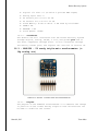
const
const
const
const
const
int
int
int
int
int
groundpin = 18;
powerpin = 19;
xpin = A3;
ypin = A2;
zpin = A1;
//
//
//
//
//
analog
analog
x-axis
y-axis
z-axis
input pin 4 -- ground
input pin 5 -- voltage
of the accelerometer
(only on 3-axis models)
void setup()
{
pinMode(groundpin, OUTPUT);
pinMode(powerpin, OUTPUT);
digitalWrite(groundpin, LOW);
digitalWrite(powerpin, HIGH);
int x;
int y;
March 8, 2013
23
Team Mass
Rocket Recovery System
int z;
}
void loop()
{
// get the x sensor values:
x=analogRead(xpin));
// get the y sensor values:
y=analogRead(ypin));
// get the z sensor values:
z=analogRead(zpin));
// delay before next reading:
delay(100);
}
March 8, 2013
24
Team Mass
Rocket Recovery System
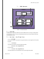
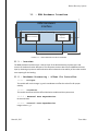
4. - IRBS User Interface
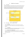
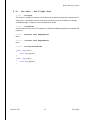
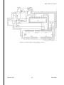
4.1 - Overview
The IRBS User Interface Layer is used for allowing the user to visually interact with the system. This
layer’s primary responsibility is to get the button presses from the user input and the processed
wind data. It then formats the data and displays it on an LCD screen. This layer consists of two
subsystems; Get Data and Display Output. Get Data Subsystem consists of one module; Get
Processed State. Display Output Subsystem consists of two modules; Format Data and Print.
FIGURE 4-1 - USER INTERFACE DIAGRAM
4.2 - Get Data - Get Processed State
4.2.1 - Prologue
The purpose of the Get Processed State module in the Get Data subsystem is to get the
processed wind data and make it available to the Format Data module of the Display Output
subsystem.
4.2.2 - Interfaces
The Get Processed State interfaces with the Set Wind Speed, Set Wind Direction, and Set Flight
Data modules in the Set Data Subsystem of the Data Processing Layer.
4.2.3 - External Data Dependencies
The module is dependent on the Set Wind Speed, Set Wind Direction, and Set Flight Data
modules for the wind data. It gets integer value of altitude and float values of pad angle, wind
speed and wind direction.
March 8, 2013
25
Team Mass
Rocket Recovery System
4.2.4 - Internal Data Dependencies
The module is not dependent on any data that is internal.
4.2.5 - Process/Pseudo code
void getWindData()
{
int altitude;
float w_speed;
float w_direction;
float pad_angle;
altitude = sd.getAlt();
w_speed = sd.getSpd();
w_direction = sd.getDir();
pad_angle = sd.getAng();
//get
//get
//get
//get
the
the
the
the
altitude
wind speed
wind direction
pad angle
}
4.3 - Display Output – Format Data
4.3.1 - Prologue
The purpose of the Format Data subsystem in the Display Output subsystem is to get the
processed wind data from the Get Processed State module. It formats the data, so that it can be
sent to the Print module for display. This module also gets the different states of the switches
and button from the Button State module. It also gets the acknowledgement from the Set ACK
module to check whether the data has been transferred successfully to the RRM.
4.3.2 - Interfaces
The Format Data interfaces with the Get Processed State module in the Get Data Subsystem. It
also interfaces with the Button State module of the Data Input Layer to get the actual button
presses and switch movements. It also interfaces with the Set ACK module of the Send/Receive
Subsystem in the Network Layer.
4.3.3 - External Data Dependencies
The module is dependent on the Get Processed State module for the processed wind data and
Button State module for the button presses and switch movements. It gets integer value of
altitude and float values of pad angle, wind speed and wind direction. It also gets a Boolean
value from the set ACK module.
4.3.4 - Internal Data Dependencies
The module is not dependent on any data that is internal.
4.3.5 - Process/Pseudo code
//get the button states
int SS1 = 0;
March 8, 2013
// variable for reading the switch1 status
26
Team Mass
Rocket Recovery System
int SS2 = 0;
int SS3 = 0;
int LBS = 0;
// variable for reading the switch2 status
// variable for reading the switch3 status
// variable for reading the launch button status
void gbs(ButtonState getState)
{
SS1 = getState.switchState1();
//switch state for setup mode
SS2 = getState.switchState2();
//switch state for preparation mode
SS3 = getState.switchState3();
//switch state for launch mode
LBS = getState.launchButtonState(); //switch state for actual launch
}
//A Boolean value from the network layer to determine whether the data has been
sent properly to the RRM, if ack is true data has been sent if ack is false data
has not been sent.
bool ack;
ack = data.getack();
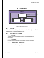
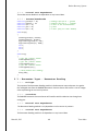
4.4 - Display Output – Print
The purpose of the Print module is to display the relevant information to the user. It displays the
different modes of the system through LCD and LEDs, and it also displays the wind speed, wind
direction, altitude, and pad angle on an LCD.
4.4.1 - Interfaces
The module interfaces with the backlight positive LCD 16x2 through six digital pins. The module
also interfaces with the LED indicator through one digital pin. It also interfaces with Get
Processed State of the Get Data Subsystem.
4.4.2 - External Data Dependencies
The module is not dependent on any data that is external.
4.4.3 - Internal Data Dependencies
The module is dependent on the Format Data module for the string of formatted data.
4.4.4 - Process/Pseudo code
#include <LiquidCrystal.h>
// initialize the library with the numbers of the interface pins
LiquidCrystal lcd(31, 33, 35 37, 41, 45);
int ledPin1 = 50;
int ledPin2 = 52;
int ledPin3 = 48;
void setup()
{
pinMode(ledPin1, OUTPUT);
standby mode
pinMode(ledPin2, OUTPUT);
preparation mode
March 8, 2013
// LED connected to digital pin 50 (Green)
// LED connected to digital pin 52 (Red)
// LED connected to digital pin 48 (Blue)
// sets the digital pin as output for
// sets the digital pin as output for
27
Team Mass
Rocket Recovery System
pinMode(ledPin3, OUTPUT);
// sets the digital pin as output for launch
mode
}
void loop()
{
//set up the LCD's number of columns and rows:
lcd.begin(16, 2);
lcd.clear();
//Print the Standby Mode
if (SS1 == 1)
{
lcd.print(" Standby Mode");
digitalWrite(ledPin1, HIGH);
delay(10000);
digitalWrite(ledPin1, LOW);
}
//set the Green LED on
//set the Green LED off
//Print the Preparation Mode
else if(SS1 == 1 && SS2 == 1)
{
lcd.clear();
lcd.setCursor(0, 0);
lcd.print(" Preparation Mode");
digitalWrite(ledPin3, HIGH);
//set the Blue LED on
/*if wind speed is less than 20 miles per hour, print the wind
speed, direction, altitude,
and pad angle*/
if (w_speed < 20.0)
{
lcd.clear();
lcd.setCursor(0, 0);
//prints the wind speed and direction
lcd.print("Speed: "); lcd.print(w_speed); lcd.print(" mph");
lcd.setCursor(0, 1);
lcd.print("Direction: "); lcd.print(w_direction)
//prints the pad angle and altitude
delay(5000);
lcd.clear();
lcd.setCursor(0, 0);
lcd.print("Angle: "); lcd.print(pad_angle);
lcd.print((char)223); //prints a degree symbol
lcd.setCursor(0, 1);
lcd.print("Altitude: "); lcd.print(altitude);
digitalWrite(ledPin3, LOW);
//set the Blue LED off
}
//if wind speed is greater than 20 miles per hour, print wind speed
and a warning
March 8, 2013
28
Team Mass
Rocket Recovery System
else if (w_speed >= 20.0)
{
lcd.clear();
lcd.setCursor(0, 0);
lcd.print("Speed: "); lcd.print(w_speed); lcd.print(" mph");
lcd.setCursor(0, 1);
lcd.print("WARNING WARNING");
}
}
//Print the launch mode
else if(SS1 == 1 && SS2 == 1 && SS3 == 1)
{
lcd.clear();
lcd.setCursor(0, 0);
lcd.print(" Launch Mode");
digitalWrite(ledPin2, HIGH);
delay(10000);
digitalWrite(ledPin2, LOW);
//set the Red LED on
//set the Red LED off
//print whether the data has been successfully transferred to the
RRM
if (ack == true)
{
lcd.clear();
lcd.setCursor(0, 0);
lcd.print("Data Sent?");
lcd.setCursor(0, 1);
lcd.print("YES");
//Start the countdown
//abort the countdown if any or all of the switch states are
equal to zero.
}
else
{
lcd.clear();
lcd.setCursor(0, 0);
lcd.print("Data Sent?");
lcd.setCursor(0, 1);
lcd.print("NO");
}
}
//print that the rocket is launched
else if(LBS == 1)
{
lcd.clear();
lcd.setCursor(0, 0);
lcd.print("Rocket Launched");
}
}
March 8, 2013
29
Team Mass
Rocket Recovery System
delay(10000);
March 8, 2013
30
Team Mass
Rocket Recovery System
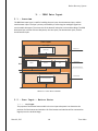
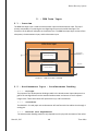
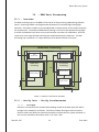
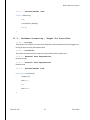
5. - IRBS Data Processing
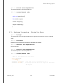
5.1 - Overview
The data processing layer on the IRBS is built to do all of the processing needed prior to launch.
Processing includes: verifying data, calculations for successful flight and operation, and storing it for
other systems to feed form. The bulk of the processing will be calculated during the preparation
phase of the launch sequence. Calculations include: average wind speed and direction, and turn
altitude for the rocket. The data processing layer represents a C++ object with each of the below
modules as functions.
D4
D2
D3
Data Processing
DP19
Encapsulate Data
Verify Data
Verify
Accelerometer
Encapsulate Wind
Data
Verify Anemometer
DP1
DP2
DP3
DP13
DP14
Process Data
DP8
Calculate Wind
Speed
Set Data
Set Wind Speed
Set Wind Direction
DP4
DP5
Calculate Wind
Direction
DP6
DP10
Set Flight Data
DP11
Tablel Lookup
DP16
DP15
DP18
DP12
DP7
DP9
DP17
FIGURE 2-1 IRBS DATA PROCESSING DIAGRAM
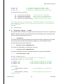
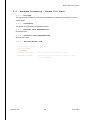
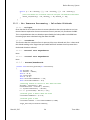
5.2 - Verify Data – Verify Accelerometer
5.2.1 - Prologue
Data that is received from the Accelerometer Reading module in the Data Input layer will be
brought to this module for verification. Verification includes filtering out extreme outliers.
Extreme outliers are defined as values that exceed the realistic value for a given calculation, in
this case any orientation value where value < 0 or value > 360.
5.2.2 - Interfaces
The Verify Accelerometer module is a function within the Data Processing class. It gets passed
values x, y, and z from which we can derive the orientation given that the rocket will be
calibrated on the IRBS pad. These calculations are done in the Data Input layer, to clarify this
function received values in degrees. Note that this will cancel out acceleration due to gravity
from the SD-12 Rockets base frame. This function returns void and calls the function
Encapsulate_Data if the values are within the threshold.
March 8, 2013
31
Team Mass
Rocket Recovery System
5.2.3 - External Data Dependences
None.
5.2.4 - Internal Data Dependences
None.
5.2.5 - Process/Pseudocode
//Verifies that the x, y, z values in g forces are not < -16 or > 16
private void Verify_Accelerometer(int x, int y, int z)
{
//If any of the three are out of bounds throw out all three
if ((x > 0 || x < 360) || (y > 0 || y < 360) || (z > 0 || z < 360))
Encapsulate_Data(x, y, z);
}
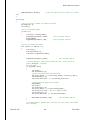
5.3 - Verify Data – Verify Anemometer
5.3.1 - Prologue
Data that is received from the RPM and Direction module in the Data Input layer will be brought
to this module for verification. Verification includes filtering out extreme outliers. Extreme
outliers are defines as values that exceed the realistic value for a given calculation, in this case
wind speed values > 20 or < 0, or direction < 0 or > 360 degrees.
5.3.2 - Interfaces
The Verify Data module is a function within the Data Processing class. It gets passed values wind
speed and direction. This function returns void and calls the function Encapsulate_Data if the
values are within the threshold.
5.3.3 - External Data Dependences
None.
5.3.4 - Internal Data Dependences
None.
5.3.5 - Process/Pseudocode
//Verifies that the speed, and direction values are within the threshold as
//defined below
private void Verify_Accelerometer(float speed, int direction)
{
//If any of the three are out of bounds throw out both
if ((speed > 0 || speed < 20) || (direction > 360 || direction < 0))
Encapsulate_Data(speed, direction);
}
5.4 - Encapsulate Data – Encapsulate Wind Data
March 8, 2013
32
Team Mass
Rocket Recovery System
5.4.1 - Prologue
Data that is received from the verify functions will be consolidated into two separate data
structures within this module. The flow of information from the verify functions is constant for
the duration of the preparation mode. Once the preparation mode is complete the function will
call the calculate wind and speed functions for further processing.
5.4.2 - Interfaces
The Encapsulate Wind Data is a function within the Data Processing class. It is called from the
verify functions and receives the gravitational forces (x, y, z), and wind speed and direction.
The accelerometer information is used to determine if the IRBS has taken an angle beyond +- 30
degrees on the x axis. If the pad has exceeded that limit essentially it has fallen over and launch
is not possible. This is a failsafe for personal safety reasons. This is ensured by sending a
boolean value to the Button State module within the Data input layer. The speed and direction
will be encapsulated into two separate arrays which the calculate functions will receive at the
end of the preparation phase or when the array is completely filled which we define by
acquiring 10000 values.
5.4.3 - External Data Dependences
None.
5.4.4 - Internal Data Dependences
None.
5.4.5 - Process/Pseudocode
//Encapsulates the and 3 axis directional information and sends boolean value to
//determine if the x
//has exceeded 30 degrees
//Button Press within the Data Input layer will look at the Data Processing
//object -> Launch variable
//to check if the IRBS is within its tilt threshold, if not is has fallen over.
private void Enpasulate_Data(int x, int y, int z)
{
//sets the local variable Launch to 1 which allows a launch.
if (x > -30 || x < 30)
{
Launch = 1;
tipOver[tipOver.Length + 1] = x;
}
else
Launch = 0; //disalows launch
}
private void Encapsulate_Data(long speed, int direction)
{
speed[speed.Length + 1] = speed;
direction[direction.Length + 1] = direction;
if (speed.Length >= 10000)
Calculate_Wind_Average(speedArray);
March 8, 2013
33
Team Mass
Rocket Recovery System
if (direction.Length >= 10000)
Calculate_Direction_Average(directionArray);
}
5.5 - Process Data – Calculate Wind Speed
5.5.1 - Prologue
The sole purpose of this function is to average each element of the array of wind speeds.
5.5.2 - Interfaces
The array of wind speed values that is received from the Encapsulate Data function will be
averaged in this function after which it will be passed to the Table Lookup function. The
resulting calculation is stored as a part of the objects private member data for the rest of the
system to access.
5.5.3 - External Data Dependences
None.
5.5.4 - Internal Data Dependences
None.
5.5.5 - Process/Pseudocode
private void Average_Speed(long[] speed)
{
long total = 0;
foreach(long s in speed)
{
total += s;
}
averageSpeed = total/10000;
}
5.6 - Process Data – Calculate Wind Direction
5.6.1 - Prologue
The sole purpose of this function is to average each element of the array of wind directions.
5.6.2 - Interfaces
The array of direction values that is received from the Encapsulate Data function will be
averaged in this function after which it will be passed to the Table Lookup function. The
resulting calculation is stored as a part of the objects private member data for the rest of the
system to access.
March 8, 2013
34
Team Mass
Rocket Recovery System
5.6.3 - External Data Dependences
None.
5.6.4 - Internal Data Dependences
None.
5.6.5 - Process/Pseudocode
private void Average_Direction(int[] direction)
{
long total = 0;
foreach(long d in direction)
{
total += d;
}
averageDirection = total/10000;
}
5.7 - Process Data – Table Lookup
5.7.1 - Prologue
Our system is going to have a set of tables that list all the possible settings for a given wind
speed and direction. These settings include the pad angle and the rockets turn altitude. Once
the averages are calculated this module will conduct the lookup for these two values and send
that data to the Set Flight Data module within the Set Data subsystem.
5.7.2 - Interfaces
The Table Lookup function will get two values, the average wind speed. It will then check the
tables that give the SD-Rocket turn altitude and rocket pad angle given the average wind speed.
These values will be stored for the rest of the system to use. The resulting calculation is stored
as a part of the objects private member data for the rest of the system to access.
5.7.3 - External Data Dependences
None.
5.7.4 - Internal Data Dependences
None.
5.7.5 - Process/Pseudocode
private void Table_Lookup()
{
for(int i = 0; i < table.Length; i++)
if (table[i][0] == averageSpeed)
padAngle = table[i][1];
}
March 8, 2013
35
Team Mass
Rocket Recovery System
5.8 - Set Data – Set Wind Speed
5.8.1 - Prologue
This function is simply the interface into the data that the Data Processing layer computes for all
other layers. It specifically contains the accessor functions for the average wind speed. Doing
this ensures encapsulation of data.
5.8.2 - Interfaces
Accessor function that return the average wind speed for any module that requests it.
5.8.3 - External Data Dependences
None.
5.8.4 - Internal Data Dependences
None.
5.8.5 - Process/Pseudocode
public long getSpd()
{
return averageSpeed;
}
5.9 - Set Data – Set Wind Direction
5.9.1 - Prologue
This function is simply the interface into the data that the Data Processing layer computes for all
other layers. It specifically contains the accessor functions for the average wind direction.
Doing this ensures encapsulation of data.
5.9.2 - Interfaces
Accessor function that return the average wind direction for any module that requests it.
5.9.3 - External Data Dependences
None.
5.9.4 - Internal Data Dependences
None.
5.9.5 - Process/Pseudocode
public long getDir()
{
return averageSpeed;
}
March 8, 2013
36
Team Mass
Rocket Recovery System
5.10 - Set Data – Set Flight Data
5.10.1 - Prologue
This function is simply the interface into the data that the Data Processing layer computes for all
other layers. It specifically contains the accessor functions for the SD-12 Rocket turn altitude
and IRBS pad angle. Doing this ensures encapsulation of data.
5.10.2 - Interfaces
Accessor function that return SD-12 Rocket turn altitude and IRBS pad angle for any module that
requests it.
5.10.3 - External Data Dependences
None.
5.10.4 - Internal Data Dependences
None.
5.10.5 - Process/Pseudocode
public long getAlt()
{
return averageSpeed;
}
public long getAng()
{
return averageSpeed;
}
March 8, 2013
37
Team Mass
Rocket Recovery System
6. - IRBS Hardware Interface
Hardware Interface
Get Data
Get Wind Data
H2
H1
Hardware Processing
Rotate Pan Servo
Rotate Tilt Servo
Tilt Servo
Pan Servo
FIGURE 6-1- HARDWARE INTERFACE DIAGRAM
6.1 - Overview
The IRBS Hardware Interface layer is a layer that depends on the Data Processing Layer and consists
of two subsystems namely Get Data and Hardware Process subsystems. The layer primary function
is to obtain the data that will be used by the servo to rotate at a specific angle and direction
depending on the speed of the wind.
6.2 - Get Data – Get Wind Data
6.2.1 - Prologue
Get Wind Data module serves as a temporary storage for the wind data received from the Set
Flight Data and Set Wind Direction modules of the Set Data Layer. These data received are used
for the tilting and rotating the servo in a specific direction and angle.
6.2.2 - Interfaces
The module only interface with the wind data modules from the Set Data Layer.
6.2.3 - External Data Dependencies
No external data
March 8, 2013
38
Team Mass
Rocket Recovery System
6.2.4 - Internal Data Dependencies
The module depends on the wind speed data
6.2.5 - Process/Pseudo code
public void getWindData(){
float windDir, angPad;
windDir = wd.getDir();
angPad = wd.getAng();
}
6.3 - Hardware Processing – Rotate Pan Servo
6.3.1 - Prologue
The module will use the average wind direction to regulate and rotate the servo to a required
angle.
6.3.2 - Interfaces
Rotate Pan Servo module interface with the Get Wind Data module
6.3.3 - External Data Dependencies
No external data
6.3.4 - Internal Data Dependencies
The module depends on the wind speed data
6.3.5 - Process/Pseudo code
//This is the objects for tilt servo.
Servo servoTilt;
void setup(){
servoTilt.attach(2);
servoTilt.write(x);
//The Tilt servo is attached to pin 2.
//Initially put the servos at angle not more than
30 degress.
}
March 8, 2013
39
Team Mass
Rocket Recovery System
6.4 - Hardware Processing – Rotate Tilt Servo
6.4.1 - Prologue
The purpose of the module is to use the wind speed data to regulate and rotate the servo to a
specific angle.
6.4.2 - Interfaces
The module interface with Get Wind Data module
6.4.3 - External Data Dependencies
No external data
6.4.4 - Internal Data Dependencies
Wind direction data
6.4.5 - Process/Pseudo code
//This is the objects for pan servo.
Servo servoPan;
void setup(){
servoPan.attach(3);
//The Pan servo is attached to pin 3.
servoPan.write(x);
//Initially put the servos at angle not more
than 30 degress.
}
March 8, 2013
40
Team Mass
Rocket Recovery System
7. - IRBS Network
Network
Get Data
Get Flight Data
N1
Send/Receive
N2
Pack Data
Send Flight Data
N5
From
RRM
N4
Unpack Data
ACK
N6
To RRM
FIGURE 7-1- NETWORK DIAGRAM
7.1 - Overview
The IRBS Network integrates the IRBS system with the RRM system by receiving or sending packets
to the RRM Network layer. The layer encodes/decodes packets receive from the Data Process layer
to the RRM Network layer.
7.2 - Get Data – Get Flight Data
7.2.1 - Prologue
Get Flight Data module is responsible for using the altitude to turn the angle that will be used by
the rocket.
7.2.2 - Interfaces
The module only interface with the Set Flight Data module
7.2.3 - External Data Dependencies
No external data
7.2.4 - Internal Data Dependencies
The module depends on the altitude data stored In the Set Flight Data module
March 8, 2013
41
Team Mass
Rocket Recovery System
7.2.5 - Process/Pseudo code
public void getFlightData(){
int windAlt;
windAlt = fd.getAlt();
}
7.3 - Send/Receive – Pack Data
7.3.1 - Prologue
The module breaks down the flight data into packets that will be sent to the RRM system
7.3.2 - Interfaces
It interfaces with the Get Flight Data module
7.3.3 - External Data Dependencies
No external data
7.3.4 - Internal Data Dependencies
Depends on flight data
7.3.5 - Process/Pseudo code
Struct A {
int windAlt;
} a;
7.4 - Send/Receive – Unpack Data
7.4.1 - Prologue
The Unpack Data module extracts the signal in Boolean form and stores in Set ACK module
7.4.2 - Interfaces
Interfaces with RRM system, Set Flight module and Set ACK module
7.4.3 - External Data Dependencies
The module depends on the packet signal coming from the RRM system
7.4.4 - Internal Data Dependencies
No internal data
March 8, 2013
42
Team Mass
Rocket Recovery System
7.4.5 - Process/Pseudo code
Struct C {
Boolean y;
} c;
7.5 - Send/Receive – Send Flight Data
7.5.1 - Prologue
The purpose of the module is to store the packet data and the Boolean value to confirm
whether the data is sent or not.
7.5.2 - Interfaces
The module interfaces with the RRM system, Pack Data module, and the Unpack Data module.
7.5.3 - External Data Dependencies
No external
7.5.4 - Internal Data Dependencies
The module depends on packet data from the Pack Data module and Boolean value from the
Unpack Data module
7.5.5 - Process/Pseudo code
private void sendFlightData(){
Struct B {
int windAlt;
Boolean x;
} b;
7.6 - Send/Receive – Set ACK
7.6.1 - Prologue
The Set ACK module stores the Boolean value that gives the result to whether the data is sent or
not.
7.6.2 - Interfaces
The module interface with the Format Data module and the Unpack Data module
7.6.3 - External Data Dependencies
No external data
March 8, 2013
43
Team Mass
Rocket Recovery System
7.6.4 - Internal Data Dependencies
Boolean value
7.6.5 - Process/Pseudo code
private boolean sendAck(){
if (true)
return 1;
else
return 0;
}
March 8, 2013
44
Team Mass
Rocket Recovery System
8. - RRM Network
Network
Send/Receive
N7
N8
Unpack
N9
N10
Pack
Send ACK
N3
FIGURE 8-1- RRM NETWORK DIAGRAM
8.1 - Overview
The RRM Network integrates the RRM system with the IRBS system by receiving or sending packets
to the IRBS Network layer. The layer receives the altitude data from the Set Flight Data module of
IRBS Network layer and sends acknowledged signal back.
8.2 - Send/Receive – Unpack
8.2.1 - Prologue
The module receives the packet data and stores it in a structure to be packed and
acknowledged.
8.2.2 - Interfaces
It interfaces with the Set Flight Data module of the IRBS system and Pack module
8.2.3 - External Data Dependencies
Altitude data
8.2.4 - Internal Data Dependencies
No internal data
March 8, 2013
45
Team Mass
Rocket Recovery System
8.2.5 - Process/Pseudo code
Struct Alt{
int altitude;
} alt;
8.3 - Send/Receive – Pack
8.3.1 - Prologue
The Pack module extracts the packet in Boolean form to determine if the data is sent or not.
8.3.2 - Interfaces
Interfaces with Unpack module
8.3.3 - External Data Dependencies
No external data
8.3.4 - Internal Data Dependencies
Boolean value
8.3.5 - Process/Pseudo code
Struct Bool{
Boolean x;
} bool;
8.4 - Send/Receive – Send ACK
8.4.1 - Prologue
The Send ACK module receives the Boolean and stores it as a structure object.
8.4.2 - Interfaces
The module interfaces with Pack module and the IRBS system
8.4.3 - External Data Dependencies
No external data
8.4.4 - Internal Data Dependencies
Boolean object
March 8, 2013
46
Team Mass
Rocket Recovery System
8.4.5 - Process/Pseudo code
private boolean sendAck(){
If (true)
return 1;
else
return 0;
}
March 8, 2013
47
Team Mass
Rocket Recovery System
9. - RRM Data Input
9.1 - Overview
The RRM Data Input Layer is used the accelerometer input and the barometer input. The layer’s
primary reasonability is converting the raw digital signal into certain usable data types. The
conversion of the data will take place in the Arduino Uno. The RRM Data Input layer consists of two
subsystems, the Anemometer Input, and the Barometer Input.
RRM Data Input
Accelerometer Input
Accelerometer
RD1
Accelerometer Reading
Barometer Input
Barometer
Barometer Reading
RD2
FIGURE 9-1 - RRM DATA INPUT DIAGRAM
9.2 - Accelerometer Input - Accelerometer Reading
9.2.1 - Prologue
The purpose of the Accelerometer Reading module in the Accelerometer Input subsystem is to
gather the raw digital data from the attached accelerometer and convert it into 3 separate
integer value. These three values will represent the X,Y, and Z coordinates.
9.2.2 - Interfaces
The ADXL326 - 5V ready triple-axis accelerometer will interface with the Arduino Uno through 3
analog pins.
9.2.3 - External Data Dependences
The Accelerometer Reading module is only dependent on the physical orientation of the rocket.
March 8, 2013
48
Team Mass
Rocket Recovery System
9.2.4 - Internal Data Dependences
The Accelerometer Module is not dependent on any internal data.
9.2.5 - Process/Pseudocode
const
const
const
const
const
int
int
int
int
int
groundpin = 18;
powerpin = 19;
xpin = A3;
ypin = A2;
zpin = A1;
//
//
//
//
//
analog
analog
x-axis
y-axis
z-axis
input pin 4 -- ground
input pin 5 -- voltage
of the accelerometer
(only on 3-axis models)
void setup()
{
pinMode(groundpin, OUTPUT);
pinMode(powerpin, OUTPUT);
digitalWrite(groundpin, LOW);
digitalWrite(powerpin, HIGH);
int x;
int y;
int z;
}
void loop()
{
// get the x sensor values:
x=analogRead(xpin));
// get the y sensor values:
y=analogRead(ypin));
// get the z sensor values:
z=analogRead(zpin));
// delay before next reading:
delay(100);
}
9.3 - Barometer Input - Barometer Reading
9.3.1 - Prologue
The purpose of the Barometer Reading module in the Barometer Input subsystem is to gather
the raw digital data from the BMP085 Barometric Pressure Sensor and convert it into an integer
value representing the current air pressure.
9.3.2 - Interfaces
The BMP085 Barometric Pressure Sensor will interface with the Arduino Uno through two
analog pins.
9.3.3 - External Data Dependences
The Barometer Reading module is only dependent on the current air pressure.
9.3.4 - Internal Data Dependences
The Barometer Reading module is not dependent on any internal data.
March 8, 2013
49
Team Mass
Rocket Recovery System
9.3.5 - Process/Pseudocode
#include "Adafruit_BMP085.h"
Adafruit_BMP085 bmp;
void setup()
{
int baroReading;
bmp.begin();
}
void loop() {
baroReading = bmp.readPressure());
delay(1);
}
March 8, 2013
50
Team Mass
Rocket Recovery System
10. - RRM Data Processing
10.1 - Overview
The Data Processing layer on the RRM is built to do all of the processing needed during and after
launch. Processing includes: verifying data and calculations for successful flight during flight
operation. Calculations include: current altitude based on the barometer, and orientation based on
the accelerometer. Essentially the RRM Data Processing is the brain of the operation during flight.
It will tell the hardware layer when to turn and orientation corrections for stabilization. Once the
rocket turns at the target altitude processing has completed and physics takes over. The data
processing layer represents a C++ object with each of the below modules as functions.
RRM Data Processing
Verify Data
RD1
Verify
Accelerometer
Stabilization
Processing
Verify Barometer
RDP3
RD2
Air Pressure
Processing
RDP1
Calculate Altitude
Offset Calculation
RDP2
RDP4
Target Interrupt
N8
RDP5
FIGURE 2-1 RRM DATA PROCESSING DIAGRAM
10.2 - Verify Data - Verify Accelerometer
10.2.1 - Prologue
Data that is received from the Accelerometer Reading module in the Data Input layer will be
brought to this module for verification. Verification includes filtering out extreme outliers.
Extreme outliers are defined as values that exceed the realistic value for a given calculation, in
this case any orientation value where value < 0 or value > 360.
March 8, 2013
51
Team Mass
Rocket Recovery System
10.2.2 - Interfaces
The Verify Accelerometer module is a function within the RRM Data Processing class. It gets
passed values x, y, and z from which we can derive the orientation given that the rocket will be
calibrated on the IRBS pad. These calculations are done in the Data Input layer; to clarify this
function received values in degrees. Note that this will cancel out acceleration due to gravity
from the SD-12 Rockets base frame. This function returns void and calls the function
Offset_Calculation if the values are within the threshold.
10.2.3 - External Data Dependences
None.
10.2.4 - Internal Data Dependences
Data from the Accelerometer Reading module in the Data Input Layer.
10.2.5 - Process/Pseudocode
//Verifies that the x, y, z values in g forces are not < -16 or > 16
private void Verify_Accelerometer(int x, int y, int z)
{
//If any of the three are out of bounds throw out all three
if ((x > 0 || x < 360) || (y > 0 || y < 360) || (z > 0 || z < 360))
Encapsulate_Data(x, y, z);
}
10.3 - Verify Data - Verify Barometer
10.3.1 - Prologue
Data that is received from the Barometer Reading module in the Data Input layer will be brought
to this module for verification. Verification includes filtering out extreme outliers. Extreme
outliers are defined as values that exceed the realistic value for a given calculation, in this case
any orientation value where value < 300 or value > 1100.
10.3.2 - Interfaces
The Verify Accelerometer module is a function within the RRM Data Processing class. It gets
passed the value of the current air pressure from which we can derive the altitude. These
calculations are done in the Calculate Altitude module. The air pressure unit is in hPa or
hectopascal which can easily be converted to bar or psi. This function returns void and calls the
function Calculate_Altitude if the values are within the threshold.
10.3.3 - External Data Dependences
None.
10.3.4 - Internal Data Dependences
Data from the Barometer Reading module in the Data Input Layer.
10.3.5 - Process/Pseudocode
March 8, 2013
52
Team Mass
Rocket Recovery System
//Verifies that the air pressure values are within the threshold as defined below
private void Vefiry_Barometer()
{
if (direction > 300 || direction < 1100)
Calculate_Altitude(int airPressure);
}
10.4 - Stabilization Processing - Offset Calculation
10.4.1 - Prologue
The stabilization of the rocket is happening during the rocket accent until the rocket turns.
Given that the F50-6 rocket motor burns for 1.37 seconds this module will be stabilizing the
rocket for about a second, which is roughly when it will reach its target turn altitude.
Stabilization is defined as correcting the rockets orientation on accent. Corrections may have to
be made if the rocket changes its roll orientation. This is critical given that the turn angle and
direction of the rocket are fixed.
10.4.2 - Interfaces
The stabilization function receives the rockets current orientation in 3 dimensional space from
the Verify Accelerometer module. With this information it will know its current orientation and
the orientation that it should be facing and thus will be able to make the correction. We are
waving the need for a PID controller given that the direction of turn is approximate within +-10
degrees because of obvious weather uncertainties. We will simulate an slightly under
dampened system by telling the rocket to orient itself to the minimum threshold of the range
and to only correct back if it exceeds the 20 degree bandwidth. Once a correction is decided to
be made the desired orientation will be sent to the Offset Fin Controller module in the hardware
layer for correction execution.
10.4.3 - External Data Dependences
None.
10.4.4 - Internal Data Dependences
None.
10.4.5 - Process/Pseudocode
private void Offset_Calculation(int x, int y, int z)
{
//desired_x = desired x orinetation
//desired_y = desired y orinetation
//desired_z = desired z orinetation
//if the current orinetation exceeds +- 10 degrees of desired orientation
if ((x - 10 < desired_x || y - 10 < desired_y || z - 10 < desired_z)
{
//call the Offset Fin Controller function and pass the desired orientation
Offset_Fin(desired_x - 10, desired_y - 10, desired_z - 10);
}
March 8, 2013
53
Team Mass
Rocket Recovery System
else if (x + 10 > desired_x || y + 10 > desired_y || z + 10 > desired_z)
{
//call the Offset Fin Controller function and pass the desired orientation
Offset_Fin(desired_x + 10, desired_y + 10, desired_z + 10);
}
}
10.5 - Air Pressure Processing - Calculate Altitude
10.5.1 - Prologue
Given that the SD-12 rocket must know its current altitude so that we know when to turn into
the wind we are required to do some conversions from air pressure, hPa, feet above the IRBS.
This is required because the turn altitude as prescribed by the lookup tables in the IRBS Data
Processing Layer were calculated using feet above the IRBS.
10.5.2 - Interfaces
This function does the conversion from air pressure, hPa, to our altitude unit, feet. It then sends
this altitude reading to the Target Interrupt module which will activate the turn process when
the desired altitude is achieved.
10.5.3 - External Data Dependences
None.
10.5.4 - Internal Data Dependences
None.
10.5.5 - Process/Pseudocode
private void Calculate_Altitude(int airPressure)
{
int altitude = 0;
int seaLevel = 101325;
float a = 0.0;
int currentTemp;
float b = 0.0;
float currentAltitudeMeters = 0.0;
float currentAltitudeFeet = 0.0;
//executing formula to convert to feet above sea level
altitude = airPressure * 100;
relativePressure = altitude / seaLevel;
x = ln(relativePressure) * 287.053;
b = x * ((currentTemp + 459.67) * 5/9);
//altitude given in meters above sea level
currentAltitudeMeters = b/-9.8;
//altitude given in feet
currentAltitudeFeet = currentAltitudeMeters/.3048;
Target_Altitude(currentAltitudeFeet);
March 8, 2013
54
Team Mass
Rocket Recovery System
}
10.6 - Air Pressure Processing - Target Interrupt
10.6.1 - Prologue
The Target Interrupt module’s only purpose is to listen to the altitude readings from the
Calculate Altitude module and send the command to turn the rocket when the target altitude is
reached.
10.6.2 - Interfaces
This function receives the target altitude from the Unpack module in the Network Layer, and the
current altitude from the Current Altitude module in the Data Input Layer. Once the current
altitude and target altitude match this module will send a bit value to the Target Fin Controller
in the Network Layer signaling it to follow it’s turn algorithm.
10.6.3 - External Data Dependences
None.
10.6.4 - Internal Data Dependences
The target altitude from Unpack module in the Network Layer
10.6.5 - Process/Pseudocode
private void Target_Altitude(float currentAltitudeFeet)
{
Target_Fin = false;
if (currentAltitudeFeet >= targetAltitude)
Target_Fin(true);
}
March 8, 2013
55
Team Mass
Rocket Recovery System
11. - RRM Hardware Interface
RRM Hardware
Interface
Hardware Processing
Target Fin
Controller
Offset Fin Controller
To Servos
FIGURE 11-1 – RRM HARDWARE INTERFACE DIAGRAM
11.1 - Overview
The RRM Hardware Interface Layer is the last layer of the Rocket Recovery System layers and
consists of Hardware Process Subsystem. The subsystem receives data from the RRM Data Process
layer by obtaining air pressure and acceleration data in determine the stability of the rocket and the
servo opening for the landing.
11.2 - Hardware Processing – Offset Fin Controller
11.2.1 - Prologue
The module will use the integer x,y,and z coordinates to offset the rocket fins for proper
stability.
11.2.2 - Interfaces
The module interfaces with the Offset Calculation module and the system servo
11.2.3 - External Data Dependencies
No external data
11.2.4 - Internal Data Dependencies
Integer values x, y, z
March 8, 2013
56
Team Mass
Rocket Recovery System
11.2.5 - Process/Pseudo code
private int offFinCon(){
int y;
y= fd.calculate_altitude();
return y;
}
11.3 - Hardware Processing – Target Fin Controller
11.3.1 - Prologue
The purpose of the module is to access the coordinate values needed by the fin and triggers the
turning of the servo using the Boolean value.
11.3.2 - Interfaces
The module interfaces with the Target Interrupt module and the system servo
11.3.3 - External Data Dependencies
No external data
11.3.4 - Internal Data Dependencies
Boolean value
11.3.5 - Process/Pseudo code
private boolean tarFinCon(){
if(Target_Fin)
return true;
else
return false;
}
March 8, 2013
57
Team Mass
Rocket Recovery System
IRBS Design
The Intelligent rotating base station, or IRBS, will consist of two servos, pan and tilt brackets, an
accelerometer, and the aluminum launch pad. The launch pad will be rotated in the proper direction by
the use of the two servos. It will also have an accelerometer to report the platform back to the launch
control box. All of these components are described in more detail in section 14.
FIGURE 11-2 - IRBS DESIGN PROFILE VIEW
March 8, 2013
58
Team Mass
Rocket Recovery System
FIGURE 11-3 - IRBS DESIGN UNDER PAD VIEW #1
FIGURE 11-4 - IRBS DESIGN UNDER PAD VIEW #2
March 8, 2013
59
Team Mass
Rocket Recovery System
FIGURE 11-5 - IRBS DESIGN ABOVE VIEW
March 8, 2013
60
Team Mass
Rocket Recovery System
12. - IRBS Hardware Design
Figures 13-1 and 13-2 show the IRBS bread board layout and schematic layout. For more details, see
section 14.
FIGURE 12-1- IRBS BREAD BOARD LAYOUT
March 8, 2013
61
Team Mass
Rocket Recovery System
FIGURE 12-2- IRBS SCHEMATIC LAYOUT
March 8, 2013
62
Team Mass
Rocket Recovery System
13. - IRBS Hardware Components
13.1 - Overview
Figures in section 12 show physical design of the IRBS. The IRBS
hardware components section shall describe all of the hardware
components used in the Intelligent Rotating Base Station. Each
component shall have a section describing its purpose,
specifications and interfaces.
13.2 - HSR-1425CR Continuous Rotation Servo
FIGURE 13-1- HSR-1425CR CONTINUOUS ROTATION SERVO
13.2.1 - Purpose
The purpose of this servo is the pan the launch pad to the
appropriate angle. This will allow the other servo to tilt in the
appropriate direction into the wind.
13.2.2 - Specifications
Control System: +Pulse Width Control 1500usec Neutral
Required Pulse: 4.8-6.0 Volt Peak to Peak Square Wave
Operating Voltage Range: 4.8-6.0 Volts
Operating Temperature Range: -20 to +60 Degree C (-4F to
+140F)
Operating Speed (4.8V): 44 RPM at no load
Operating Speed (6.0V): 52 RPM at no load
Operating Torque (4.8V): 38.8 oz-in (2.8 kg-cm)
Operating Torque (6.0V): 42 oz-in (3.1 kg-cm)
Direction: Clockwise/Pulse Traveling 1500 to 1900usec
March 8, 2013
63
Team Mass
Rocket Recovery System
Connector Wire Length: 7" (178mm)
Dimensions: 1.59" x 0.77"x 1.44" (40.6 x 19.8 x 36.6mm)
Weight: 1.47oz (41.7g)
13.2.3 - Interfaces
The HSR-1425CR Continuous Rotation Servo will interface with the
Arduino Mega inside of the Launch Control Box. It will use one
digital pin on the Arduino; see figures 13-1 and 13-2 of section
13.
13.3 - HS-645MG Servo Motor
FIGURE 13-2 - HS-645MG SERVO MOTOR
13.3.1 - Purpose
The purpose of this servo is to tilt the launch pad to an
appropriate angle into the wind.
13.3.2 - Specifications
Control System: +Pulse Width Control 1500usec Neutral
Required Pulse: 3-5 Volt Peak to Peak Square Wave
Operating Voltage: 4.8-6.0 Volts
Operating Temperature Range: -20 to +60 Degree C
Operating Speed (4.8V): 0.24sec/60° at no load
Operating Speed (6.0V): 0.20sec/60° at no load
Stall Torque (4.8V): 106.93 oz/in. (7.7kg.cm)
Stall Torque (6.0V): 133.31 oz/in. (9.6kg.cm)
Operating Angle: 45 Deg. one side pulse traveling 400usec
360 Modifiable: Yes
March 8, 2013
64
Team Mass
Rocket Recovery System
Direction: Clockwise/Pulse Traveling 1500 to 1900usec
Connector Wire Length: 11.81" (300mm)
Dimensions: 1.59" x 0.77"x 1.48" (40.6 x 19.8 x 37.8mm)
Weight: 1.94oz. (55.2g)
13.3.3 - Interfaces
The HS-645MG Servo will interface with the Arduino Mega inside of
the Launch Control Box. It will use one analog pin on the
Arduino; see figures 13-1 and 13-2 of section 13.
13.4 - ADXL326 - 5V ready triple-axis accelerometer (+16g analog out)
FIGURE 13-3 - ADXL326 - 5V READY TRIPLE-AXIS ACCELEROMETER
13.4.1 - Purpose
The purpose of the ADXL326 accelerometer is to measure the launch
pad angle. The accelerometer is a safety feature to ensure that
the pad does not over tilt its 30 degree maximum.
13.4.2 - Specifications
Sensing Range :±19g
Sensitivity: 57mV/g
Voltage - Supply:1.8 V ~ 3.6 V
March 8, 2013
65
Team Mass
Rocket Recovery System
13.4.3 - Interfaces
The ADXL326 accelerometer will interface with the Arduino Mega
inside of the Launch Control Box. It will use three analog pins
on the Arduino; see figures 13-1 and 13-2 of section 13.
13.5 - DDT500 Direct Drive Tilt System
FIGURE 13-4 - DDT500 DIRECT DRIVE TILT SYSTEM
13.5.1 - Purpose
The Purpose of the DDT500 Direct Drive Tilt System is to provide
two brackets that the two servos connect to. This will allow for
flawless pan and tilt of the launch platform.
13.5.2 - Specifications
• 1/4” ABS plastic
• Max supported weight: 2 lbs
13.5.3 - Interfaces
The DDT500 Direct Drive Tilt System has no interface with any
electronic device. It is attached via screws to the two servos.
13.6 - Adafruit Perma-Proto Quarter-sized Breadboard PCB
March 8, 2013
66
Team Mass
Rocket Recovery System
FIGURE 13-5- ADAFRUIT PERMA-PROTO QUARTER-SIZED BREADBOARD PCB
13.6.1 - Purpose
The Adafruit Perma-Proto Quarter-sized Breadboard PCB will allow
connections to the Arduino Mega in the launch control box. This
will allow for the accelerometer to have power and data flow.
13.6.2 - Specifications
15 rows of double 5-hole rows
4 power rails with positive/negative markings
1.7" x 2.0" (44mm x 55mm), 0.063" thick FR4
1.2mm / 0.047" drill holes
2 x 0.125" or 3.2mm mounting holes 1.4" apart
13.6.3 - Interfaces
The Adafruit perma-proto quarter-sized breadboard PCB interfaces
with the Arduino Mega in the launch control box through a 5-volt
pin and ground pin to power the rest of the system; see figures
13-1 and 13-2 of section 13.
March 8, 2013
67
Team Mass
Rocket Recovery System
14. - Launch Control Box Design
The Launch Control Box will consist of multiple switches, buttons, LED indicators, an LCD screen, a data
port to control the IRBS, and connection to the rocket ignition system. The rocker switch will control the
power of the unit. The three large control switches will allow the user to change the modes. The large
red button will launch the rocket. The LED lights are used for debugging the system and the LCD screen
allows the system to display data to the user. All of these components are described in more detail in
section 17.
FIGURE 14-1-LAUNCH CONTROL BOX VIEW #1
March 8, 2013
68
Team Mass
Rocket Recovery System
FIGURE 14-2-LAUNCH CONTROL BOX VIEW #2
March 8, 2013
69
Team Mass
Rocket Recovery System
FIGURE 14-3-LAUNCH CONTROL BOX VIEW #3
March 8, 2013
70
Team Mass
Rocket Recovery System
FIGURE 14-4-LAUNCH CONTROL BOX VIEW #4
March 8, 2013
71
Team Mass
Rocket Recovery System
15. - Launch Control Box Hardware Design
Figures 16-1 and 16-2 show launch control box bread board layout and schematic layout. For more
details, see section 17.
FIGURE 16-1-LAUNCH CONTROL BOX BREAD BOARD LAYOUT
March 8, 2013
72
Team Mass
Rocket Recovery System
FIGURE 16-2-LAUNCH CONTROL BOX SCHEMATIC LAYOUT
March 8, 2013
73
Team Mass
Rocket Recovery System
16. - Launch Control Box Hardware Components
16.1 - Overview
Figures in section 15 show physical design of the launch control
box. The launch control box hardware components section shall
describe all of the hardware components used in the Launch Control
Box. Each component shall have a section describing its purpose,
specifications and interfaces.
16.2 - Arduino Mega
FIGURE 16-2 - ARDUINO MEGA
16.2.1 - Purpose
The Arduino Mega 2560 R3 DEV-11061 is to act as the mother board
of the Rocket Recovery System. It will handle all the
computations necessary for the system to function correctly and
distribute power to the other hardware components.
16.2.2 - Specifications
Microcontroller: ATmega1280
Operating Voltage: 5V
Input Voltage (recommended): 7-12V
Input Voltage (limits): 6-20V
Digital I/O Pins: 54 (of which 15 provide PWM output)
Analog Input Pins: 16
DC Current per I/O Pin: 40 mA
DC Current for 3.3V Pin: 50 mA
March 8, 2013
74
Team Mass
Rocket Recovery System
Flash Memory: 128 KB of which 4 KB used by bootloader
SRAM: 8 KB
EEPROM: 4 KB
Clock Speed: 16 MHz
16.2.3 - Interfaces
The Arduino Mega 2560 will interfaces with the Rocket Recovery
System through digital, analog, TX/RX, 5 volt, and ground pins
and to the other components through wires. It also interfaces
through the battery holder port.
16.3 - Davis Anemometer, Standard (#7911)
FIGURE 16-3 - ANEMOMETER, STANDARD (#7911)
16.3.1 - Purpose
The purpose of the anemometer is to gather the wind speed and
direction data.
16.3.2 - Specifications
Cable Type : 4-conductor, 26 AWG
Connector: . Modular connector (RJ-11)
16.3.3 - Interfaces
The anemometer will connect to a digital pin, and use a 4k7
resistor as pull up to + 5v and use a 10 to 22nF capacitor
from the pin to ground to debounce the reed switch of
anemometer. It will also connect to an analog pin and use a 1
to 10 µF / 16v capacitor between the pin and ground (observe C
polarity) to avoid jitter.
March 8, 2013
75
Team Mass
Rocket Recovery System
16.4 - Rocker Switch – SPST
FIGURE 16-4-ROCKER SWITCH – SPST
16.4.1 - Purpose
The purpose of the rocker switch is to allow the user to turn on
and off the power of the rocket recovery system.
16.4.2 - Specifications
Right angle solid through hole mounting
Rated up to 16A @ 125V
16.4.3 - Interfaces
The Rocker Switch will interface with the Arduino Mega 5 volt
power and ground.
16.5 - Toggle Switch and Cover - Illuminated (Red)
FIGURE 16-5 - TOGGLE SWITCH AND COVER - ILLUMINATED
March 8, 2013
76
Team Mass
Rocket Recovery System
16.5.1 - Purpose
The purpose of the toggle switch and cover is to allow the users
to switch between all the modes the Rocket Recovery Systems uses.
The cover is an extra safety feature to prevent the user from
accidently flipping a switch. The switches will also illuminate
when active so the user knows when a modes are active.
16.5.2 - Specifications
Rated for 12V 20A
Includes Missile Switch Cover
Illuminated
16.5.3 - Interfaces
The Switch will interface with 1 Arduino Mega digital pin. It
will also need to be connected to 5v power supply and ground to
provide the Illumination. Also we will need a 10K ohm pull-down
resistor between the input pin and ground on the Arduino. The
Arduino’s internal resistors are pull-up and won’t work here so
we need to do this manually.
16.6 - Concave Button – Red
FIGURE 16-6 - CONCAVE BUTTON – RED
16.6.1 - Purpose
The purpose the Concave Button is to allow the user to launch the
rocket after the countdown has finished.
16.6.2 - Specifications
Microswitch: max 3A @ 120 VAC
Microswitch reliability tested to 10,000,000 cycles
Includes 3 terminal microswitch
Net weight: 25g
March 8, 2013
77
Team Mass
Rocket Recovery System
16.6.3 - Interfaces
The Switch will interface with 1 Arduino Mega digital pin.
16.7 - RGB backlight positive LCD 16x2
FIGURE 16-7 - RGB BACKLIGHT POSITIVE LCD 16X2
16.7.1 - Purpose
The purpose of the RGB backlight positive LCD 16x2 is to allow
the system to send output to the user in some readable format.
16.7.2 - Specifications
16 characters wide, 2 rows
Black text on multi-color background
Connection port is 0.1" pitch, single row for easy
breadboarding and wiring
Single RGB LED backlight included can be dimmed easily with
a resistor or PWM and uses much less power than LCD with EL
(electroluminescent) backlights
Built in character set supports English/Japanese text, see
the HD44780 datasheet for the full character set
Up to 8 extra characters can be created for custom glyphs
or 'foreign' language support
16.7.3 - Interfaces
The RGB backlight positive LCD 16x2 interfaces with the Arduino
Mega though 6 digital pins. (Any analog/digital pins can be used)
and 3 PWM pins for the backlight; see figures 16-1 and 16-2 of
section 16.
16.8 - LED Indicators
March 8, 2013
78
Team Mass
Rocket Recovery System
FIGURE 16-8 - LED INDICATORS
16.8.1 - Purpose
The purpose of the LED indicators is to allow the system to
notify the user modes and problems.
16.8.2 - Specifications
5mm diameter
660 nm wavelength
1.85-2.5V Forward Voltage, at 20mA current
250 mcd typical brightness
16.8.3 - Interfaces
The LED Indicators interface with one digital pin on the Arduino
Mega; see figures 16-1 and 16-2 of section 16.
16.9 - Relay SPDT Sealed
FIGURE 16-9 - RELAY SPDT SEALED
March 8, 2013
79
Team Mass
Rocket Recovery System
16.9.1 - Purpose
The purpose of the relay is to close the circuit on the attached
9v battery launcher circuit. The purpose of this circuit is to
send the charge to the rocket engine fuse.
16.9.2 - Specifications
5V DC SPDT Relay
Rated up to 5A
Fully Sealed
16.9.3 - Interfaces
Interfaces with the 9 volt battery circuit.
16.10 - Battery Holder
FIGURE 16-10 - BATTERY HOLDER
16.10.1 - Purpose
The purpose of the battery holder is to distribute power to the
Launch Control Box provided by the rechargeable 9V battery.
16.10.2 - Specifications
This is a 9V battery pack with on/off switch and a pre-attached
5.5mm/2.1mm barrel plug.
16.10.3 - Interfaces
The battery holder provides power to the Launch Control Box by
interfacing with the Arduino.
March 8, 2013
80
Team Mass
Rocket Recovery System
16.11 - 9 Volt Battery
FIGURE 16-2 - 9 VOLT BATTERY
16.11.1 - Purpose
The purpose of the 9V battery is to provide power to the Launch
Control Box.
16.11.2 - Specifications
Provide 9 volts.
16.11.3 - Interfaces
The 9 volt battery provides power to the Launch Control Box by
interfacing with the battery holder.
March 8, 2013
81
Team Mass
Rocket Recovery System
17. - RRM Hardware Design
Figures 18-1 and 18-2 show RRM bread board layout and schematic layout. For more details, see section
19.
FIGURE 18-1-RRM BREAD BOARD LAYOUT
March 8, 2013
82
Team Mass
Rocket Recovery System
FIGURE 18-2-RRM SCHEMATIC LAYOUT
March 8, 2013
83
Team Mass
Rocket Recovery System
18. - RRM Hardware Components
18.1 - Overview
The hardware section shall describe all of the hardware components
used in the Rocket Recovery Module. Each component shall have a
section describing its purpose, specifications and interfaces.
18.2 - Arduino Uno
FIGURE 18-1 - ARDUINO UNO
18.2.1 - Purpose
The Arduino Uno is to act as the mother board of the Rocket
Recovery System. It will handle all the computations necessary
for the system to function correctly and distribute power to the
other hardware components.
18.2.2 - Specifications
Microcontroller: ATmega328
Operating Voltage: 5V
Input Voltage (recommended): 7-12V
Input Voltage (limits): 6-20V
March 8, 2013
84
Team Mass
Rocket Recovery System
Digital I/O Pins: 14 (of which 6 provide PWM output)
Analog Input Pins: 6
DC Current per I/O Pin: 40 mA
DC Current for 3.3V Pin: 50 mA
Flash Memory: 32 KB of which .5 KB used by bootloader
SRAM: 2 KB
EEPROM: 1 KB
Clock Speed: 16 MHz
18.2.3 - Interfaces
The Arduino Uno will interfaces with the Rocket Recovery System
through digital, analog, TX/RX, 5 volt, and ground pins and to
the other components through wires. It also interfaces through
the battery holder port; see figures 18-1 and 18-2 of section 18.
18.3 - ADXL326 - 5V ready triple-axis accelerometer (+16g analog out)
FIGURE 18-2- ADXL326 - 5V READY TRIPLE-AXIS ACCELEROMETER
18.3.1 - Purpose
The purpose of the ADXL326 accelerometer is to measure the change
in position of the rocket during flight so that calculations can
be made to stabilize the rocket.
March 8, 2013
85
Team Mass
Rocket Recovery System
18.3.2 - Specifications
Sensing Range :±19g
Sensitivity: 57mV/g
Voltage - Supply:1.8 V ~ 3.6 V
18.3.3 - Interfaces
The ADXL326 accelerometer will interface with the Arduino Uno
inside of the Rocket (RRM). It will use three analog pins on the
Arduino; see figures 18-1 and 18-2 of section 18.
18.4 - BMP085 Barometric Pressure/Temperature/Altitude
Sensor- 5V ready
FIGURE 18-3- BMP085 BAROMETRIC PRESSURE/TEMPERATURE/ALTITUDE SENSOR
18.4.1 - Purpose
The purpose of the BMP085 Barometric Pressure Sensor is to
measure the current air pressure the rocket is at. The air
pressure can be used to calculate the current altitude of the
rocket.
18.4.2 - Specifications
March 8, 2013
86
Team Mass
Rocket Recovery System
Logic: 3 to 5V compliant
Pressure sensing range: 300-1100 hPa (9000m to -500m
above sea level)
Up to 0.03hPa / 0.25m resolution
-40 to +85°C operational range, +-2°C temperature
accuracy
18.4.3 -
Interfaces
The BMP085 Barometric Pressure Sensor will interface with the
Arduino Uno inside of the Rocket (RRM). It will use two analog
pins on the Arduino; see figures 18-1 and 18-2 of section 18.
18.5 - HS-645MG Servo Motor
FIGURE 18-4 - HS-645MG SERVO MOTOR
18.5.1 - Purpose
The purpose of this servo is to move the attached control surface
to stabilize and turn the rocket.
18.5.2 - Specifications
Control System: +Pulse Width Control 1500usec Neutral
Required Pulse: 3-5 Volt Peak to Peak Square Wave
Operating Voltage: 4.8-6.0 Volts
Operating Temperature Range: -20 to +60 Degree C
Operating Speed (4.8V): 0.24sec/60° at no load
Operating Speed (6.0V): 0.20sec/60° at no load
March 8, 2013
87
Team Mass
Rocket Recovery System
Stall Torque (4.8V): 106.93 oz/in. (7.7kg.cm)
Stall Torque (6.0V): 133.31 oz/in. (9.6kg.cm)
Operating Angle: 45 Deg. one side pulse traveling 400usec
360 Modifiable: Yes
Direction: Clockwise/Pulse Traveling 1500 to 1900usec
Connector Wire Length: 11.81" (300mm)
Dimensions: 1.59" x 0.77"x 1.48" (40.6 x 19.8 x 37.8mm)
Weight: 1.94oz. (55.2g)
18.5.3 - Interfaces
The HS-645MG Servo will interface with the Arduino Uno inside of
the rocket (RRM). It will use one analog pin on the Arduino; see
figures 18-1 and 18-2 of section 18.
18.6 - Battery Holder
FIGURE 18-50 - BATTERY HOLDER
18.6.1 - Purpose
The purpose of the battery holder is to distribute power to the
Launch Control Box provided by the rechargeable 9V battery.
18.6.2 - Specifications
This is a 9V battery pack with on/off switch and a pre-attached
5.5mm/2.1mm barrel plug.
18.6.3 - Interfaces
The battery holder provides power to the Launch Control Box by
March 8, 2013
88
Team Mass
Rocket Recovery System
interfacing with the Arduino; see figures 18-1 and 18-2 of
section 18.
18.7 - 9 Volt Battery
FIGURE 18-6 - 9 VOLT BATTERY
18.7.1 - Purpose
The purpose of the 9V battery is to provide power to the Launch
Control Box.
18.7.2 - Specifications
Provide 9 volts.
18.7.3 - Interfaces
The 9 volt battery provides power to the Launch Control Box by
interfacing with the battery holder.
March 8, 2013
89
Team Mass
Rocket Recovery System
19. - SD-12 Rocket Design
19.1 - Rocket Design
FIGURE 7 - ROCKET DESIGN 3D
FIGURE 8 - ROCKET DESIGN 2D
March 8, 2013
90
Team Mass
Rocket Recovery System
19.2 - Rocket Motor Specifications
March 8, 2013
91
Team Mass
Rocket Recovery System
20. - SD-12 Components
RRM Section
Servo
Servo
March 8, 2013
92
Team Mass
Rocket Recovery System
21. - Traceability Matrices
In order to verify that certain customer and performance requirements are satisfied, Team MASS used
requirements traceability matrix. Requirements traceability matrix is produced by generating a table,
which specifies the modules that fulfill certain requirements.
Modules
Button State
RPM
Direction
Calibrate
Accelerometer Reading
Get Processed State
Format Data
Print
Verify Accelerometer
Verify Anemometer
Encapsulate Wind Data
Calculate Wind Speed
Calculate Wind Direction
Table Lookup
Set Wind Speed
Set Wind Direction
Set Flight Data
Get Wind Data
Rotate Pan Servo
Rotate Tilt Servo
Get Flight Data
Pack Data
Send Flight Data
Unpack Data
Set ACK
Unpack
Pack
March 8, 2013
5.6 RRM – Microcontroller
instructions per second
5.5 IRBS Modes - Time
3.12 IRBS Wind Speed
Detection
3.11 RRS Abort
Countdown
3.10 IRBS Pad Pitch
3.9 IRBS Rotation
3.6 IRBS – Launch Mode
3.5 IRBS – Preparation
Mode
3.1 Rocket lands where it
was launched from
Requirements
93
Team Mass
Rocket Recovery System
Send ACK
Accelerometer Reading
Barometer Reading
Verify Accelerometer
Verify Barometer
Calculate Altitude
Target Interrupt
Offset Calculation
Offset Fin Controller
Target Fin Controller
March 8, 2013
94
Team Mass
Rocket Recovery System
22. - Quality Assurance
22.1 - Test Plans and Procedures
Team Mass will take advantage of the modularity of the project design in carrying out the testing to
achieve maximum productivity and efficiency. For a start each component will be tested using unit
testing to be sure that no component is faulty or damaged before soldering. Then the group of
components that made up a particular module will be tested together for functionality. On passing
the test, the module will be tested with other modules in the same subsystem after which the
subsystem will be tested with other subsystems in the same layer using the integration testing.
Finally, the system verification testing will be conducted to ensure all the customer
requirements are met and the system is robust by testing all the layers together as one.
The team other ways of testing the quality and completeness of the design are requirement
mapping and test cases. The Detailed Designed Specification (DDS) was tested for design
completeness by static testing against the requirements. As shown in requirement mapping,
each requirement is matched against a set of design components. Rows that have no
corresponding design components were requirements that do not have any consideration in the
design. Some of the test cases will be provided in this chapter. However, complete and
thorough test cases will only be provided only in System Test Plan.
22.2 - Module/Unit Test
23.2.1 Data Input Layer
23.2.1.1
User Input
The User Input shall be able to detect and respond to physical button presses from the
user as well as convert the digital signal into a usable software object.
23.2.1.2
Anemometer Input
The Anemometer Input shall be able to calibrate the analog digital input from the
anemometer and convert it to digital signal for verification.
23.2.1.3
Accelerometer Input
The Accelerometer Input shall be able to detect and read the analog digital input from
the accelerometer for verification.
23.2.2 User Interface Layer
23.2.2.1
Get Data
The Get Data unit shall be able to accept and process all the data states into digital
signal that will be easy to format for display. The data expected to be processed are
wind direction, altitude, pad angle, and wind speed.
March 8, 2013
95
Team Mass
Rocket Recovery System
23.2.2.2
Display Output
The Display Output unit shall be able to format the signal received from the Get Data
unit into an appropriate format for display on the LCD.
23.2.3 Data Processing Layer
23.2.3.1
Verify Data
The unit shall be able to access and verify the accuracy of the data from
accelerometer and anemometer.
23.2.3.2
Encapsulate Data
Encapsulate Data unit shall be able to convert data from raw form to wind speed in
M/PH and wind direction in degree.
23.2.3.3
Set Data
Set Data unit shall be able to serve as a temporary storage to store calculated wind
direction and speed as well as flight data.
23.2.3.4
Process Data
The unit shall be able to compute wind speed and wind direction from the
encapsulate wind data and create tables for lookup.
23.2.4 IRBS Hardware Interface Layer
23.2.4.1
Get Data
The Get Data unit shall be able to store wind temporarily for further processing and
uses by the servos.
23.2.4.2
Hardware Processing
Hardware Processing unit shall be able to tilt the servo to a specific angle and pan the
servo to a required angle using wind data.
23.2.5 IRBS Network Layer
23.2.5.1
Get Data
The unit shall be able to store flight data temporarily before being converted into
packets appropriate uses.
23.2.5.2
Send/Receive
Send/Receive unit shall be able to pack, unpack, and acknowledge the flight data
received from the Get Data module and send the data to RRM system.
March 8, 2013
96
Team Mass
Rocket Recovery System
23.2.6 RRM Network Layer
23.2.6.1
Send/Receive
Send/Receive unit shall be able to unpack the data received from the IRBS system,
unpack, acknowledge and send the data back to the IRBS system.
23.2.7 RRM Data Input Layer
23.2.7.1
Barometer Input
The Barometer Input shall be able to calibrate the analog digital input from the
anemometer and convert it to digital signal for verification.
23.2.7.2
Accelerometer Input
The Accelerometer Input shall be able to detect and read the analog digital input from
the accelerometer for verification.
23.2.8 RRM Data Processing Layer
23.2.8.1
Verify Data
The unit shall be able to access and verify the accuracy of the data from
accelerometer and barometer.
23.2.8.2
Stabilization Processing
Stabilization Processing unit shall be able to counterbalance and compensate
calculation for controlling the rocket fin.
23.2.8.3
Air Pressure Process
The Air Pressure Process unit shall be able to convert air pressure from the barometer
to be used to compute altitude needed for successful landing of the rocket.
23.2.9 RRM Hardware Interface Layer
23.2.9.1
Hardware Processing
Hardware Processing shall be able to use the wind speed to compensate for the
movement and turning of the fin by the servos.
March 8, 2013
97
Team Mass
Rocket Recovery System
23. - Acceptance Plan
23.1 - Overview
This section describes the minimum criteria that must be met by the Rocket Recovery System in
order to be considered acceptable by the customer and other stakeholders.
23.2 - Packaging and Installation
The Rocket Recovery System shall contain the following physical components:
23.2.1 - Intelligent Rotating Base Station
o HSR – 1425CR Continuous Rotation Servo
o HS – 64MG Servo Motor
o ADXL326 – 5V Ready Triple-axis Accelerometer
o DDT500 Direct Drive Tilt System
o Adafruit Perma-Proto Quarter-sized Breadboard PCB
23.2.2 - Launch Control Box
o Arduino Mega 2560 R3 DEV-11061
o Davis Anemometer, Standard (#7911)
o Rocket Switch – SPST
o Toggle Switch and Cover – Illuminated (Red)
o Concave Button - Red
o RGB backlight positive LCD 16x2
o LED indicators
o Relay SPDT Sealed
o 9 Volt Battery
o Battery Holder
o Instruction Manual
23.2.3 - Rocket Recovery Module
o Arduino Uno
o ADXL326 – 5V Ready Triple-axis accelerometer (+- 16g analog out)
o BMP085 Barometric Pressure/Temperature/Altitude Sensor – 5V Ready
o HS – 645MG Servo Motor
o 9 Volt Battery
o Battery Holder
23.2.4 - SD-12 Rocket
o Nose Cone
o Body Tubes
o Parachute
o Shroud Lines
March 8, 2013
98
Team Mass
Rocket Recovery System
o
o
o
o
o
o
Tube Coupler
Shock Cord
Launch Lugs
Bulkhead
Clipped Delta Fins
Centering Rings
23.3 - Acceptance Testing
System testing shall be conducted to ensure that the Rocket Recovery System meets the acceptance
criteria. The Rocket Recovery System shall go through module, subsystem, layer, integration, and
overall system testing. The details of the testing shall be provided in the System Test Plan document.
23.4 - Acceptance Criteria
The following requirements must be met in order for the Rocket Recovery System to be considered
acceptable.
Requirement
Name
No.
Rocket lands
3.1
where
launched from
Simple User
3.2
Interface
Reusability
3.3
3.4
IRBS – Standby
Mode
3.5
IRBS –
Preparation
Mode
IRBS – Launch
Mode
3.6
3.7
IRBS – Rocket
Stability
Section
3.8
3.9
Low Powered
IRBS - Rotation
March 8, 2013
Description
The system will launch a model rocket and land it within a 50 foot
radius from the area where it was launched.
The system will be easy for user to use. This will require less input
from the customer thereby make the operation simple
The system will be made of non-breakable components. The
customer will be able to use the system again by changing the
engine and putting it back together.
The base station will have a standby mode. The standby mode will
be the mode used during setup and preparation prior to entering the
preparation mode.
The preparation mode will be the active state of the base station in
which environment variables are read, calculations made, and
proper positioning conducted to prepare for the launch stage.
The launch stage will last 30 seconds. In this stage there will be no
more wind data collection and the aggregated wind data will be sent
to the Rocket Recovery Module inside the SD-12 Rocket. The base
station will be in its final launch position.
To ensure stability of the rocket while on the base station during
high winds. This section of the base station contains the rods that
the SD-12 Rockets lugs ride along to guide it during the first few feet
of the launch. There will be a second rod that runs perpendicular to
the first and the rocket will have two sets of lugs that will ride along
the two rods.
The system will use common everyday 9 volt batteries.
Based on the anemometer the IRBS will rotate to orient itself and
99
Team Mass
Rocket Recovery System
3.10
3.11
3.12
4.1
4.2
4.3
5.3
5.4
5.5
5.6
7.1
7.4
8.1
8.2
8.3
8.4
March 8, 2013
the SD-12 rocket into the wind.
IRBS – Pad
Based on the anemometer the IRBS will pitch the pad at an angle
pitch
into the wind depending on its strength.
RRS – Abort
The countdown will be aborted if one or all of the switches are
Countdown
flipped down.
IRBS – Wind
The anemometer mounted on the IRBS will be used to feed wind
Speed
speed data to the IRBS microcontroller. This will be used to compute
Detection
the time and angle that the SD-12 Rocket will take on ascent.
Hardware
The packaging will include the Intelligent Rotating Base Station and
the SD-12 Rocket. The Rocket will be equipped with a Rocket
Recovery Module. The anemometer will be included in the package,
and the user will have to attach it to the Intelligent Rotating Base
Station. The user will have to buy engines, batteries, and wadding
separately. The user will also have to do minor assembling.
Software
The software will be embedded in the Rocket Recovery Module and
the Intelligent Rotating Base Station.
User Manual
A user manual will be included for user’s assistance.
RRS – Battery
The Rocket Recovery System battery life should last at least one
Life
launch cycle.
RRS – Outdoor The Rocket Recovery System will function outside in normal
Use
conditions.
IRBS Modes –
The Intelligent Rocket Base Station will have 3 modes with the
Times
following time constraints for each: standby, no time constraint.
Preparation: 2 minutes minimum, 3 maximum. Launch: strictly 30
seconds.
RRM –
The processing power of the microcontroller will be fast enough to
Microcontroller make stability correction that ensure smooth flight through the end
instructions
of the burn.
per cycle
Documentation The RRS will come with a setup manual that outlines in detail the
setup and launch procedures. This manual will include safety
guidelines to follow to ensure that the user is safe throughout the
entire operation.
Launch
A launch procedure, with outlined checks at each mode of the IRBS,
Procedure
will be provided to ensure a successful launch.
Rocket Engine
The rocket must not use motor with more than 160 Newton-seconds
Power
of total impulse (an “H” motor of larger) or multiple motors that all
together exceeds 320 Newton-seconds. It must also not use a motor
with more than 80 Newtons average thrust.
Rocket Engine
The rocket engine must not exceed 125 grams of propellant.
Propellant
Rocket Weight The rocket must not weigh more than 1,500 grams including
motor(s).
Rocket
The rocket must use only lightweight, non-metal parts for the nose,
Materials
body, and fins.
100
Team Mass
Rocket Recovery System
March 8, 2013
101
Team Mass