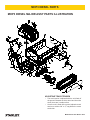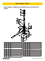
1
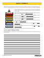
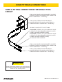
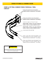
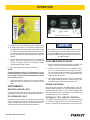
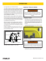
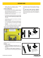
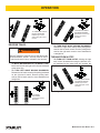
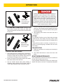
MHP3
DIESEL
TRACHORSE
USER MANUAL
Safety, Operation and Maintenance
© 2014 Stanley Black & Decker, Inc.
New Britain, CT 06053
U.S.A.
69887 10/2014 Ver. 5
TABLE OF CONTENTS
SAFETY SYMBOLS...................................................................................................................................................4
SAFETY PRECAUTIONS...........................................................................................................................................5
TOOL STICKERS & TAGS.........................................................................................................................................7
HOSE TYPES.............................................................................................................................................................8
HOSE RECOMMENDATIONS...................................................................................................................................9
HTMA REQUIREMENTS..........................................................................................................................................10
HOSE & FITTING CONNECTIONS FOR SINGLE TOOL CIRCUIT........................................................................ 11
HOSE & FITTING CONNECTIONS FOR DUAL TOOL CIRCUIT............................................................................12
OPERATION.............................................................................................................................................................13
MAINTENANCE.......................................................................................................................................................19
TESTING & TROUBLESHOOTING.........................................................................................................................20
TROUBLESHOOTING.............................................................................................................................................21
SPECIFICATIONS....................................................................................................................................................22
ACCESSORIES.......................................................................................................................................................22
MHP3 DIESEL MAJOR ASSY PARTS ILLUSTRATION...........................................................................................23
MHP3 DIESEL MAJOR ASSY PARTS LIST.............................................................................................................24
MHP3 DIESEL HOSE & FITTINGS ILLUSTRATION – A.........................................................................................25
MHP3 DIESEL HOSE & FITTINGS PARTS LIST – A...............................................................................................26
MHP3 DIESEL HOSE & FITTINGS ILLUSTRATION & PARTS – B.........................................................................27
MHP3 DIESEL POWER UNIT FRAME ILLUSTRATION..........................................................................................28
MHP3 DIESEL POWER UNIT FRAME PARTS LIST...............................................................................................29
MHP3 DIESEL POWER UNIT ENGINE ILLUSTRATION & PARTS .......................................................................30
MHP3 DIESEL POWER UNIT RESERVOIR ILLUSTRATION & PARTS ................................................................ 31
MHP3 DIESEL POWER UNIT VALVE ILLUSTRATION & PARTS...........................................................................32
IMPORTANT
To fill out a Product Warranty Validation form, and for information on your warranty,
visit Stanleyhydraulics.com and select the Company tab, Warranty.
(NOTE: The warranty Validation record must be submitted to validate the warranty).
SERVICING: This manual contains safety, operation, and routine maintenance instructions. Stanley Hydraulic
Tools recommends that servicing of hydraulic tools, other than routine maintenance, must be performed by an authorized and certified dealer. Please read the following warning.
WARNING
SERIOUS INJURY OR DEATH COULD RESULT FROM THE IMPROPER REPAIR OR
SERVICE OF THIS TOOL.
REPAIRS AND / OR SERVICE TO THIS TOOL MUST ONLY BE DONE BY AN
AUTHORIZED AND CERTIFIED DEALER.
For the nearest authorized and certified dealer, call Stanley Hydraulic Tools at the number listed on the back of this
manual and ask for a Customer Service Representative.
MHP3 Diesel User Manual ◄ 3
SAFETY SYMBOLS
Safety symbols and signal words, as shown below, are used to emphasize all operator, maintenance and repair actions which, if not strictly followed, could result in a life-threatening situation, bodily injury or damage to equipment.
This is the safety alert symbol. It is used to alert you to potential personal injury
hazards. Obey all safety messages that follow this symbol to avoid possible
injury or death.
DANGER
This safety alert and signal word indicate an imminently hazardous situation
which, if not avoided, will result in death or serious injury.
WARNING
This safety alert and signal word indicate a potentially hazardous situation
which, if not avoided, could result in death or serious injury.
CAUTION
This safety alert and signal word indicate a potentially hazardous situation
which, if not avoided, could result in death or serious injury.
CAUTION
This signal word indicates a potentially hazardous situation which, if not avoided, may result in property damage.
NOTICE
This signal word indicates a situation which, if not avoided, will result in damage
to the equipment.
IMPORTANT
This signal word indicates a situation which, if not avoided, may result in damage to the equipment.
Always observe safety symbols. They are included for your safety and for the protection of the tool.
LOCAL SAFETY REGULATIONS
Enter any local safety regulations here. Keep these instructions in an area accessible to the operator and maintenance personnel.
4 ► MHP3 Diesel User Manual
SAFETY PRECAUTIONS
Tool operators and maintenance personnel must always
comply with the safety precautions given in this manual
and on the stickers and tags attached to the machine.
These safety precautions are given for your safety. Review them carefully before operating the machine and
before performing general maintenance or routine service.
Supervising personnel should develop additional precautions relating to the specific work area and local
safety regulations. If so, place the added precautions in
the space provided in this manual.
If you have not read this manual or the engine manual, you are not ready to operate the MHP3. Read and
understand this manual and any stickers and tags
attached to the machine before operation. Failure to
do so can result in equipment damage, personal injury, or death.
•
Operate the machine in a work area WITHOUT BYSTANDERS. The operator must be familiar with all
prohibited work areas such as excessive slopes and
dangerous terrain conditions.
•
DO NOT RIDE ON, OR ALLOW ANYONE ELSE TO
RIDE ON, THE MACHINE AT ANY TIME.
•
Establish a training program for all operators to ensure safe operation.
•
DO NOT operate the machine unless thoroughly
trained or under the supervision of an instructor.
•
Always wear safety equipment such as goggles,
ear, head protection, respiratory and safety shoes
at all times when operating the TracHorse and hydraulic tools.
•
DO NOT inspect or clean the machine while the engine is running. Accidental engagement of the machine can cause serious injury or death.
•
Wear a homologated respirator when cutting or
breaking masonry, concrete, asbestos and other
materials that produce dust.
•
The hydraulic circuit control levers must be in the
“OFF”position when coupling or uncoupling hydraulic tools. Wipe all couplers clean before connecting.
Use only lint-free cloths. Failure to do so may result
in damage to the quick couplers and cause overheating of the hydraulic system.
•
Before operating hydraulic tools, read and understand the operation manual furnished with the tool.
•
DO NOT operate a damaged, or improperly adjusted,
machine. DO NOT operate with guards removed.
•
DO NOT weld or cut with an acetylene torch any
surface or component of the equipment. Consult
with the Stanley factory before performing any welding or acetylene cutting of the equipment.
•
Prevent possible personal injury or equipment damage by having all repair, maintenance and service
performed only by authorized and properly trained
personnel.
•
DO NOT operate the machine ACROSS excessive
slopes or unstable terrain where “tip over” is a hazard.
•
DO NOT operate the machine in confined areas
where there may be a risk of crushing the operator
between the machine and another object.
•
DO NOT OPERATE THE TRACHORSE IN ENCLOSED SPACES. Inhalation of engine exhaust
can be fatal.
•
DO NOT WEAR LOOSE CLOTHING that can get
entangled in the working parts of the machine or hydraulic tools.
•
•
DO NOT add fuel to the machine while it is running
or still hot.
DO NOT exceed the rated limits of the equipment
or use the equipment for applications beyond its design capacity.
•
•
DO NOT operate the machine if a fuel odor is present.
Always keep critical markings, such as labels and
warning stickers legible.
•
•
DO NOT operate the machine within 3.3 ft./1 m of
buildings, obstructions, or flammable objects.
Always replace parts with replacement parts recommended by Stanley Hydraulic Tools.
•
•
Allow the engine to cool before storing the machine
in an enclosure.
Keep all body parts away from working parts of the
TracHorse.
•
Be aware of surrounding hazards. Noise created by
the TracHorse and the tools it operates may mask
early indications of approaching hazards.
MHP3 Diesel User Manual ◄ 5
SAFETY PRECAUTIONS
•
Only use the TracHorse in well-ventilated areas. DO
NOT operate in explosive atmospheres, in closed
environments or near flammable substances.
•
Always be well-rested and mentally alert when operating the TracHorse and tools. DO NOT operate if
affected by medications, drugs or alcohol.
•
Keep clear of hot (engine) parts and exhaust.
•
DO NOT use flammable solvents around the engine.
•
DO NOT reverse tool rotation by changing fluid flow
direction.
•
Always use hose and fittings rated for 2500 psi/172
bar with a 4 to 1 safety factor. Be sure all hose connections are tight.
6 ► MHP3 Diesel User Manual
•
Be sure all hoses are correct for current flow direction to and from the tool being used.
•
DO NOT inspect hoses and fittings for leaks by using bare hands. “Pin-hole” leaks can penetrate the
skin.
•
DO NOT operate tools if oil temperature exceeds
140 °F/60 °C. Operation at high temperatures can
cause higher than normal temperatures at the tools
which can result in operator discomfort.
•
Disconnect battery before servicing electrical components. Electrocution or burns could result from
improper contact.
TOOL STICKERS & TAGS
Refer to the parts illustrations for correct location of stickers.
Use in well ventilated areas only. Exhaust contains chemicals known to the
state of California to cause cancer, birth defects, and other reproductive
harm.
Contact with high pressure fluid at leak or burst resulting from
improper handling, operation, or maintenance will cause oil injection
to body.
Engine, exhaust, and other surfaces of tool may be hot. Avoid accidental
contact with hot surfaces. Allow tool to cool before maintenance or
storage.
All operators must read, understand, and follow ALL saftey precautions
and operating instructions found in owners manual before operating tool.
68335
Throttle Sticker
59126
Dash Decal
35677
Start Sticker
28046
Carbon Monoxide Sticker
Hot Parts Sticker
P/N-28047
51297
Fluid Level Sticker
29133
California Proposition Sticker
68334
Limit Engine Speed Sticker
HYDRAULIC FLUID
35686
Hydraulic Fluid Sticker
47352
Lift Point Sticker
28045
Combiner Knob Sticker
MHP3 Diesel User Manual ◄ 7
HOSE TYPES
The rated working pressure of the hydraulic hose must be equal to or higher than the relief valve setting on the hydraulic system. There are three types of hydraulic hose that meet this requirement and are authorized for use with
Stanley Hydraulic Tools. They are:
Certified non-conductive — constructed of thermoplastic or synthetic rubber inner tube, synthetic fiber braid
reinforcement, and weather resistant thermoplastic or synthetic rubber cover. Hose labeled certified nonconductive is the only hose authorized for use near electrical conductors.
Wire-braided (conductive) — constructed of synthetic rubber inner tube, single or double wire braid reinforcement, and weather resistant synthetic rubber cover. This hose is conductive and must never be used near
electrical conductors.
Fabric-braided (not certified or labeled non-conductive) — constructed of thermoplastic or synthetic rubber inner tube, synthetic fiber braid reinforcement, and weather resistant thermoplastic or synthetic rubber cover. This
hose is not certified non-conductive and must never be used near electrical conductors.
HOSE SAFETY TAGS
To help ensure your safety, the following DANGER tags are attached to all hose purchased from Stanley Hydraulic
Tools. DO NOT REMOVE THESE TAGS.
If the information on a tag is illegible because of wear or damage, replace the tag immediately. A new tag may be
obtained from your Stanley Distributor.
D A N G E R
D A N G E R
1.
FAILURE TO USE HYDRAULIC HOSE LABELED AND CERTIFIED AS NON-CONDUCTIVE
WHEN USING HYDRAULIC TOOLS ON OR NEAR ELECTRIC LINES MAY RESULT IN
DEATH OR SERIOUS INJURY.
FOR PROPER AND SAFE OPERATION MAKE SURE THAT YOU HAVE BEEN PROPERLY TRAINED IN CORRECT PROCEDURES REQUIRED FOR WORK ON OR AROUND
ELECTRIC LINES.
2.
BEFORE USING HYDRAULIC HOSE LABELED AND CERTIFIED AS NON-CONDUCTIVE
ON OR NEAR ELECTRIC LINES. WIPE THE ENTIRE LENGTH OF THE HOSE AND FITTING WITH A CLEAN DRY ABSORBENT CLOTH TO REMOVE DIRT AND MOISTURE AND
TEST HOSE FOR MAXIMUM ALLOWABLE CURRENT LEAKAGE IN ACCORDANCE WITH
SAFETY DEPARTMENT INSTRUCTIONS.
3.
DO NOT EXCEED HOSE WORKING PRESSURE OR ABUSE HOSE. IMPROPER USE
OR HANDLING OF HOSE COULD RESULT IN BURST OR OTHER HOSE FAILURE.
KEEP HOSE AS FAR AWAY AS POSSIBLE FROM BODY AND DO NOT PERMIT DIRECT
CONTACT DURING USE. CONTACT AT THE BURST CAN CAUSE BODILY INJECTION
AND SEVERE PERSONAL INJURY.
4.
HANDLE AND ROUTE HOSE CAREFULLY TO AVOID KINKING, ABRASION, CUTTING, OR
CONTACT WITH HIGH TEMPERATURE SURFACES. DO NOT USE IF KINKED. DO NOT
USE HOSE TO PULL OR LIFT TOOLS, POWER UNITS, ETC.
5.
CHECK ENTIRE HOSE FOR CUTS CRACKS LEAKS ABRASIONS, BULGES, OR DAMAGE TO COUPLINGS IF ANY OF THESE CONDITIONS EXIST, REPLACE THE HOSE
IMMEDIATELY. NEVER USE TAPE OR ANY DEVICE TO ATTEMPT TO MEND THE HOSE.
6.
AFTER EACH USE STORE IN A CLEAN DRY AREA.
SEE OTHER SIDE
SIDE 1
SEE OTHER SIDE
(Shown smaller than actual size)
DO NOT REMOVE THIS TAG
DO NOT REMOVE THIS TAG
THE TAG SHOWN BELOW IS ATTACHED TO “CERTIFIED NON-CONDUCTIVE” HOSE
SIDE 2
D A N G E R
D A N G E R
1.
DO NOT USE THIS HYDRAULIC HOSE ON OR NEAR ELECTRIC LINES. THIS HOSE IS
NOT LABELED OR CERTIFIED AS NON-CONDUCTIVE. USING THIS HOSE ON OR NEAR
ELECTRICAL LINES MAY RESULT IN DEATH OR SERIOUS INJURY.
5.
CHECK ENTIRE HOSE FOR CUTS CRACKS LEAKS ABRASIONS, BULGES, OR DAMAGE TO
COUPLINGS IF ANY OF THESE CONDITIONS EXIST, REPLACE THE HOSE IMMEDIATELY.
NEVER USE TAPE OR ANY DEVICE TO ATTEMPT TO MEND THE HOSE.
2.
FOR PROPER AND SAFE OPERATION MAKE SURE THAT YOU HAVE BEEN PROPERLY
TRAINED IN CORRECT PROCEDURES REQUIRED FOR WORK ON OR AROUND ELECTRIC LINES.
6.
AFTER EACH USE STORE IN A CLEAN DRY AREA.
3.
DO NOT EXCEED HOSE WORKING PRESSURE OR ABUSE HOSE. IMPROPER USE OR
HANDLING OF HOSE COULD RESULT IN BURST OR OTHER HOSE FAILURE. KEEP HOSE
AS FAR AWAY AS POSSIBLE FROM BODY AND DO NOT PERMIT DIRECT CONTACT
DURING USE. CONTACT AT THE BURST CAN CAUSE BODILY INJECTION AND SEVERE
PERSONAL INJURY.
4.
HANDLE AND ROUTE HOSE CAREFULLY TO AVOID KINKING, CUTTING, OR CONTACT
WITH HIGH TEMPERATURE SURFACES. DO NOT USE IF KINKED. DO NOT USE HOSE TO
PULL OR LIFT TOOLS, POWER UNITS, ETC.
SEE OTHER SIDE
SEE OTHER SIDE
SIDE 1
SIDE 2
(Shown smaller than actual size)
8 ► MHP3 Diesel User Manual
DO NOT REMOVE THIS TAG
DO NOT REMOVE THIS TAG
THE TAG SHOWN BELOW IS ATTACHED TO “CONDUCTIVE” HOSE.
All hydraulic hose must meet or exceed
specifications as set forth by SAE J517.
All hydraulic hose must have at least a rated
minimum working pressure equal to the maximum hydraulic system relief valve setting.
This chart is intended to be used for hydraulic
tool applications only based on Stanley Hydraulic Tools tool operating requirements and
should not be used for any other applications.
The chart to the right shows recommended
minimum hose diameters for various hose
lengths based on gallons per minute (gpm)/
liters per minute (lpm). These recommendations are intended to keep return line pressure
(back pressure) to a minimum acceptable level to ensure maximum tool performance.
Tool to Hydraulic Circuit Hose
Recommendations
15-34
MM
Inside Diameter
INCH
USE
(Press/Return)
PSI
up to 10
up to 3
3/8
10
Both
2250
49-60
13-16
FLOW >>>
RETURN
<<< FLOW
PRESSURE
26-100
up to 25
100-200
51-100
up to 50
100-300
51-100
up to 50
26-100
up to 25
8-30
up to 8
30-60
15-30
up to 15
30-90
15-30
up to 15
7.5-30
up to 7.5
Figure 1. Typical Hose Connections
49-60
38-49
10-13
13-16
19-40
5-10.5
38-49
19-40
5-10.5
10-13
19-40
5-10.5
38-49
15-23
10-13
15-23
4-6
19
25.4
16
19
19
25.4
5/8
3/4
3/4
1
19
3/4
1
16
3/4
16
19
3/4
5/8
16
5/8
5/8
16
13
13
10
5/8
1/2
1/2
3/8
Return
Pressure
Return
Pressure
Return
Pressure
Return
Pressure
Both
Return
Pressure
Both
Both
Both
Both
2500
2500
2500
2500
2500
2500
2500
2500
2500
2500
2500
2500
2500
2500
2500
175
175
175
175
175
175
175
175
175
175
175
175
175
175
175
155
BAR
Min. Working Pressure
Certified Non-Conductive Hose - Fiber Braid - for Utility Bucket Trucks
METERS
Hose Lengths
FEET
Conductive Hose - Wire Braid or Fiber Braid -DO NOT USE NEAR ELECTRICAL CONDUCTORS
4-6
4-9
LPM
Oil Flow
GPM
HOSE RECOMMENDATIONS
MHP3 Diesel User Manual ◄ 9
HTMA / EHTMA REQUIREMENTS
HTMA / EHTMA REQUIREMENTS
HTMA
HYDRAULIC SYSTEM REQUIREMENTS
TYPE I
Nominal Operating Pressure
(at the power supply outlet)
4-6 gpm
(15-23 lpm)
1500 psi
(103 bar)
TOOL TYPE
TYPE II
TYPE RR
7-9 gpm
(26-34 lpm)
1500 psi
(103 bar)
9-10.5 gpm
(34-40 lpm)
1500 psi
(103 bar)
System relief valve setting
(at the power supply outlet)
2100-2250 psi
(145-155 bar)
2100-2250 psi
(145-155 bar)
2200-2300 psi
(152-159 bar)
2100-2250 psi
(145-155 bar)
Maximum back pressure
(at tool end of the return hose)
250 psi
(17 bar)
250 psi
(17 bar)
250 psi
(17 bar)
250 psi
(17 bar)
Measured at a max. fluid viscosity of:
(at min. operating temperature)
400 ssu*
400 ssu*
400 ssu*
400 ssu*
(82 centistokes) (82 centistokes) (82 centistokes) (82 centistokes)
Temperature: Sufficient heat rejection
capacity to limit max. fluid temperature to:
(at max. expected ambient temperature)
140° F
(60° C)
Flow Range
140° F
(60° C)
140° F
(60° C)
TYPE III
11-13 gpm
(42-49 lpm)
1500 psi
(103 bar)
140° F
(60° C)
3 hp
5 hp
6 hp
7 hp
Min. cooling capacity at a temperature
(2.24 kW)
(3.73 kW)
(5.22 kW)
(4.47 kW)
difference of between ambient and fluid
40° F
40° F
40° F
40° F
temps
(22° C)
(22° C)
(22° C)
(22° C)
NOTE:
Do not operate the tool at oil temperatures above 140° F (60° C). Operation at higher temperatures can cause operator
discomfort at the tool.
Filter
Min. full-flow filtration
Sized for flow of at least:
(For cold temp. startup and max.
dirt-holding capacity)
25 microns
30 gpm
(114 lpm)
Hydraulic fluid Petroleum based
(premium grade, anti-wear, non-conductive)
Viscosity (at min. and max. operating temps)
100-400 ssu*
25 microns
30 gpm
(114 lpm)
25 microns
30 gpm
(114 lpm)
100-400 ssu*
100-400 ssu*
(20-82 centistokes)
25 microns
30 gpm
(114 lpm)
100-400 ssu*
NOTE:
When choosing hydraulic fluid, the expected oil temperature extremes that will be experienced in service determine the
most suitable temperature viscosity characteristics. Hydraulic fluids with a viscosity index over 140 will meet the requirements
over a wide range of operating temperatures.
*SSU = Saybolt Seconds Universal
EHTMA
HYDRAULIC SYSTEM
REQUIREMENTS
CLASSIFICATION
B
C
D
Nominal Operating Pressure
(at the power supply outlet)
3.5-4.3 gpm
(13.5-16.5 lpm)
1870 psi
(129 bar)
4.7-5.8 gpm
(18-22 lpm)
1500 psi
(103 bar)
7.1-8.7 gpm
(27-33 lpm)
1500 psi
(103 bar)
9.5-11.6 gpm
(36-44 lpm)
1500 psi
(103 bar)
11.8-14.5 gpm
(45-55 lpm)
1500 psi
(103 bar)
System relief valve setting
(at the power supply outlet)
2495 psi
(172 bar)
2000 psi
(138 bar)
2000 psi
(138 bar)
2000 psi
(138 bar)
2000 psi
(138 bar)
Flow Range
NOTE: These are general hydraulic system requirements. See tool specification page for tool specific requirements
10 ► MHP3 Diesel User Manual
HOSE FITTINGS & CONNECTIONS
HOSE & FITTING CONNECTIONS FOR SINGLE TOOL
CIRCUIT
HTMA 3/8 INCH MALE QUICK DISCONNECT COUPLER
(STANLEY P/N 03973 COUPLER NOSE or STANLEY P/N
03971 COUPLER SET – nose & body)
HTMA 3/8 INCH FEMALE QUICK DISCONNECT
COUPLER (STANLEY P/N 03972 COUPLER BODY or
STANLEY P/N 03971 COUPLER SET – nose & body)
1/2 INCH I.D. HOSE, 25 FT TO 50 FT LONG.
(FOR 25 FEET, STANLEY P/N 31972 HYDRAULIC HOSE
or STANLEY P/N 58633 TWINNED HYDRAULIC HOSES
or 58451 2-wire braid HYDRAULIC HOSE)
(FOR 50 FEET, STANLEY P/N 31848 HYDRAULIC HOSE
or STANLEY P/N 58634 TWINNED HYDRAULIC HOSES
or 58448 2-wire braid HYDRAULIC HOSE)
1/2 INCH MALE PIPE HOSE END
HTMA 1/2 INCH MALE QUICK DISCONNECT COUPLER
(STANLEY P/N 03975 COUPLER NOSE or STANLEY P/N
03974 COUPLER SET – nose & body)
HTMA 1/2 INCH FEMALE QUICK DISCONNECT
COUPLER (STANLEY P/N 03976 COUPLER BODY or
STANLEY P/N 03974 COUPLER SET – nose & body)
CAUTION
Before disconnecting hydraulic tools, ensure the tool
circuit control levers are in the down position and the
throttle is in the "SLOW" position.
MHP3 Diesel User Manual ◄ 11
HOSE FITTINGS & CONNECTIONS
HOSE & FITTING CONNECTIONS FOR DUAL TOOL
CIRCUIT
HTMA 3/8 INCH MALE QUICK DISCONNECT
COUPLER (STANLEY P/N 03973 COUPLER NOSE or
STANLEY P/N 03971 COUPLER SET – nose & body)
HTMA 3/8 INCH FEMALE QUICK DISCONNECT
COUPLER (STANLEY P/N 03972 COUPLER BODY or
STANLEY P/N 03971 COUPLER SET – nose & body)
1/2 INCH I.D. HOSE, 25 FT TO 50 FT LONG.
(FOR 25 FEET, STANLEY P/N 31972 HYDRAULIC
HOSE or STANLEY P/N 58633 TWINNED HYDRAULIC
HOSES or 58451 2-wire braid HYDRAULIC HOSE)
(FOR 50 FEET, STANLEY P/N 31848 HYDRAULIC
HOSE or STANLEY P/N 58634 TWINNED HYDRAULIC
HOSES or 58448 2-wire braid HYDRAULIC HOSE)
1/2 INCH MALE PIPE HOSE END
HTMA 1/2 INCH MALE QUICK DISCONNECT COUPLER (STANLEY P/N 03975 COUPLER NOSE or
STANLEY P/N 03974 COUPLER SET – nose & body)
HTMA 1/2 INCH FEMALE QUICK DISCONNECT COUPLER (STANLEY P/N 03976 COUPLER BODY or
STANLEY P/N 03974 COUPLER SET – nose & body)
CAUTION
Before disconnecting hydraulic tools, ensure the tool
circuit control levers are in the down position and the
throttle is in the "SLOW" position.
12 ► MHP3 Diesel User Manual
OPERATION
PREPARATION FOR USE
RECOMMENDED HYDRAULIC OILS
ENGINE
Below is a list of recommended oils by brand.
Brand
NOTICE
Do not operate the TracHorse until you have read
the engine operating and maintenance instructions
manual furnished in addition to this manual.
1. Engine Crankcase Oil Level
Always check the oil level before starting the engine.
Make sure the oil level is at the FULL MARK on the
dipstick. Do not overfill. Use oil as specified in the
engine operating and maintenance manual.
NOTICE
The engine oil sump must never be overfilled.
Overfilling can cause the engine to overheat and
cause crankshaft seal damage.
2. Engine Fuel Level
Check the fuel level. If low, fill with DF-1 or DF-2
diesel fuel (A.S.T.M. D975-66T No. 1 or no. 2 dark).
NOTICE
Shut the engine off before attempting to add fuel to
the fuel tank. Do not remove the fuel cap while the
engine is running. Do not add fuel to the tank while
the engine is hot. Do not fill the fuel tank to a point of
overflowing.
HYDRAULIC FLUID
Check the sight gauge in the hydraulic fluid reservoir for
the proper fluid level.
Biodegradable
Description
CITGO
No
Hydurance AW32
AMS Oil
No
HVH 32
Exxon Mobil
No
Univis HVI26*
Exxon Mobil
No
DTE 10 Excel
Shell
No
S2 V 32
Chevron
No
Rando HDZ 32
Conoco Phillips
No
Unax AW-WR-32
Clarion (CITGO)
Yes
Green Bio 32
Exxon Mobil
Yes
EAL 224H
Chevron
Yes
Clarity AW32
Terresolve
Yes
Envirologic 132
Shell
Yes
Naturelle HF-E-32
*Recommended for extreme cold temperatures
BATTERY
The supplied battery is maintenance free.
NOTE:
Before starting the engine make sure the tool circuit
switch is in the OFF position.
DUAL CIRCUIT OPERATION
Facing the panel, the male quick disconnect fittings are
the PRESSURE FLUID OUT fitting. The female quick
disconnect fittings are the RETURN FLUID IN (RETURN) fitting.
The “Dual Circuit” control panel contains connections for
two 5 GPM tool circuits. In addition, the two circuits may
be combined into one 10 GPM tool circuit.
1. If using one 5 GPM tool circuit, select either circuit
and connect the PRESSURE FLUID OUT hose to
the male coupler and connect the RETURN FLUID
IN (RETURN) to the female coupler near to it. Connect the other ends of the hoses to the tool.
If using both 5 GPM tool circuits, connect PRESSURE FLUID OUT hoses to the male couplers and
connect the RETURN FLUID IN (RETURN) hoses
to the female couplers. Connect the other ends of
the hoses to the tools.
2. Ensure the throttle control is depressed fully to the
idle position.
MHP3 Diesel User Manual ◄ 13
OPERATION
Dash Panel Warning Lights
3. Ensure the tool circuit levers are in the OFF position.
NOTICE
4. If starting the engine in cold weather conditions turn
the start switch until the battery charge light comes
on. Then press and hold the glow plug button for 1015 seconds. Release the glow plug button and turn
the start switch to the third start position to crank the
engine.
If the engine runs out of fuel or dies during operation
or if the stop knob is pulled and the ignition switch
is left in the ON position, the battery may become
discharged. Make sure the start switch is returned to
the OFF position.
5. Turn the start switch clockwise to begin cranking the
engine. Use short starting cycles (15 seconds per
minute) to prolong starter life. Extended cranking
can damage the starter motor.
6. After the engine starts, allow it to warm-up.
NOTE:
Hydraulic fluids are thicker in cold weather. It is recommended that the engine be operated at low idle
long enough to allow the fluid temperature to warm
to a minimum of 50 °F.
7. When the engine is warmed up the throttle may be
advanced and the hydraulic tool circuits may be
used.
INSTRUMENTS
COLD WEATHER STARTUP
1. Use the procedures described under “Starting The
Engine” and then follow the procedures below.
2. Hydraulic fluids are thicker in cold weather, therefore, it is recommended that the engine be run at
low idle long enough to bring the fluid temperature
up to a minimum of 50 °F/10 °C or until the top of the
hydraulic filter feels warm.
3. If the tools and tool hoses are cold, it is recommended to allow hydraulic fluid to circulate through the
tool hoses until warm before using the tools.
ENGINE SHUTDOWN
A problem with the charging circuit exists if the battery
charge light remains on after the engine has started.
Place both control levers in the OFF position. Push the
throttle control completely in. Allow the engine to idle for
approximately one minute, turn the switch to OFF, and
then pull the stop knob to shutdown the unit. Make sure
the start switch is in the off position.
OIL PRESSURE LIGHT
HYDRAULIC TOOL CIRCUIT CONTROLS
BATTERY CHARGE LIGHT
A problem with the engine oil lubricating system exists
if the oil pressure light remains on after the engine has
started. Shutdown the engine and then have the lubricating system serviced by a qualified technician.
14 ► MHP3 Diesel User Manual
The MHP3 TracHorse provides two circuits, each with
an oil flow of 5 gpm/19 lpm up to 2000 psi/140 bar. Or
the two circuits may be combined into one circuit provid-
OPERATION
ing 10 gpm/38 lpm up to 2000 psi/140 bar.
The MHP3 TracHorse contains a hydraulic pump with
two sections. Each pump section will provide 5 gpm/19
lpm at the maximum, governed engine throttle. The output (5 gpm/19 lpm) of each pump section is directed to
the panel control valve assembly. It is the position of
the hydraulic circuit combiner knob on the panel control
valve assembly which keeps the output of each pump
section separated or combined.
When the hydraulic circuit combiner knob is pulled out,
the two circuits are combined into one 10 gpm/38 lpm
circuit. One hydraulic tool may be connected to one circuit. The other circuit must not have a tool connected to
it or have the hoses connected. The circuit is activated
by pushing both control levers up.
When the hydraulic circuit combiner knob is pushed in,
the two circuits are not combined and each circuit provides 5 gpm/19 lpm. One hydraulic tool may be connected to each circuit. Each circuit is activated by pushing
the circuit lever up.
VARIOUS TYPES OF WORK
WARNING
When first learning to operate the Track Horse,
position the throttle to the “SLOW” position. More
experienced operators may use higher throttle
settings.
FORWARD TRAVEL
•
The throttle can be positioned anywhere between
slow and fast for traveling forward depending on the
weight of the load being carried. Heavy loads will
require higher throttle settings and low range in order for the engine to provide enough power to move
the load.
•
A switch mounted on the control provides two-speed
(FAST & SLOW) operation.
Oil flow is regulated by pulling the throttle control to the
full throttle position. This setting will produce 10 gpm/38
lpm up to 2000 psi/140 bar.
Male Quick Disconnect Couplers
Combiner Knob
Hour Meter
REVERSE TRAVEL
Control Lever
(shown in OFF
position)
WARNING
Female Quick Disconnect Couplers
DO NOT attempt to travel in reverse with the throttle
positioned above “SLOW”. This may result in loss of
control and result in injury or death to the operator.
ADJUSTING THROTTLE FOR
•
Always position the throttle to a slow position for reverse travel to permit increased control and safety.
MHP3 Diesel User Manual ◄ 15
OPERATION
•
Always switch the two-speed control to “LOW”
speed operation when moving in reverse.
SLOPE OPERATION
•
DO NOT operate the machine on slopes exceeding 60 percent (30°) in the travel direction or across
slopes exceeding 45 percent (24°).
•
Depending on the load carried in the bed, it may be
preferable to back up steep slopes.
•
If traversing over large obstructions such as railroad
rail or curbs, travel at an angle (45 degrees) to the
obstruction. In some cases it may be easier to back
over them.
•
Avoid turning on slopes. If you must turn, turn slowly
downhill, if possible.
•
DO NOT operate the machine near drop-offs, ditches, or embankments. The machine could suddenly
turn over if a track goes over the edge or if an edge
collapses.
•
DO NOT try to stabilize the machine if it is tipping
over. Let go of the machine and get out of its way.
the right track control. Resume pushing forward on
the left track control to move forward in a straight
line.
•
TO TURN RIGHT WHILE MOVING FORWARD:
Release the right track control while pushing forward on the left track control. Resume pushing forward on the right track control to move forward in a
straight line.
TRAVELING FORWARD OR REVERSE
TO TRAVEL FORWARD
Move Both Controls
Forward
Track Steering Controls
To travel forward, reverse, turn left, or turn right, do the
following:
FORWARD TRAVEL
•
TO MOVE FORWARD IN A STRAIGHT LINE: Move
both the left and right track controls forward at the
same time.
•
TO TURN LEFT WHILE MOVING FORWARD: Release the left track control while pushing forward on
16 ► MHP3 Diesel User Manual
TO TURN LEFT WHILE
MOVING FORWARD
Release left control while
holding right control
forward
OPERATION
TO TURN LEFT WHILE
MOVING BACKWARD
Release left control while
holding right control
backward
TO TURN RIGHT WHILE
MOVING FORWARD
Release right control
while holding left control
forward
REVERSE TRAVEL
•
WARNING
DO NOT attempt to travel in reverse with the throttle
positioned above “SLOW”. This may result in loss of
control and result in injury or death to the operator.
•
TO MOVE BACKWARDS IN A STRAIGHT LINE:
Move both the left and right track controls backward
at the same time.
•
TO TURN LEFT WHILE MOVING BACKWARD:
Release the left track control while pulling backward
on the right track control. Resume pulling backward on the left track control to move backward in a
straight line.
TO TURN RIGHT WHILE MOVING BACKWARD:
Release the right track control while pulling backward on the left track control. Resume pulling backward on the right track control to move backward in
a straight line.
TURNING FROM A STOP
•
TO TURN LEFT FROM A STOP: Moving the right
track control forward and moving the left track control backward at the same time will increase the
TO TURN RIGHT WHILE
MOVING BACKWARD
Release right control
while holding left control
backward
turning rate.
TO TRAVEL
BACKWARD
Move Both Controls
Backward
MHP3 Diesel User Manual ◄ 17
OPERATION
TO TURN LEFT
FROM A STOP
Move the right control
forward and the left
control backward
•
TO TURN RIGHT FROM A STOP: Moving the left
track control forward and moving the right track
control backward at the same time will increase the
turning rate.
Loading and unloading of any type of machine is
dangerous. Never attempt to load or unload the
machine without loading ramps or a loading dock.
Loading ramps must be strong enough, have a low
angle, and correct height. Load and unload the
machine on a level surface. Never attempt to load
or unload the machine if the ramp incline exceeds
15 degrees. Failure to follow these instructions may
result in serious injury or death.
4. Drive the machine onto the trailer backwards (engine first). This will help prevent instability and keeps
the operator “up hill” from the machine during loading and unloading.
5. After loading, place chocks at the front and rear of
the tracks.
LIFTING
TO TURN RIGHT
FROM A STOP
Move the left control
forward and the right
control backward
The unloaded TracHorse can be lifted using the single
central lift point. Some safety rules may require 3-point
lifting. (Center lift point plus 2-points on forward side of
rails.)
If lifting with any items in the bed, a 3-point lift is required. (A 3-point lifting sling is available, refer to Accessories page.)
TRANSPORTING
LOADING AND UNLOADING
1. Use loading ramps or a loading dock to load and unload the machine. Ensure loading ramps are strong
enough to support the load. When using ramps, do
not exceed a 15 degree incline (27 percent).
2. Ensure the wheels of the trailer and the tow vehicle
have been chocked front and rear.
3. Use the “SLOW” throttle setting when loading or
unloading. Always switch the two-speed control to
“LOW” speed operation when moving in reverse.
18 ► MHP3 Diesel User Manual
1. Read the instructions for loading and unloading in
this section.
2. Use chains and binders to secure the load to the
trailer.
ROUTINE MAINTENANCE
Good maintenance practices will keep the machine on
the job and increase its service life.
A very important maintenance practice is to keep the hydraulic fluid clean at all times. Contaminated hydraulic
MAINTENANCE
fluid causes rapid wear and/or failure of internal parts.
must be visible in the sight gauge at all times.
Follow the maintenance instructions contained in the engine manual.
Secure the filler cap before restarting the engine.
ENGINE MAINTENANCE
Follow the maintenance schedule and general maintenance instructions in the engine maintenance and operation manual furnished with the unit. Normal maintenance includes:
•
Check the air filter daily. Clean if necessary.
•
Replace dry air filter every 200 hours of operation.
•
Replace fuel filter every 100 hours of operation.
•
Change engine oil after first 50 hours of operation,
then after every 200 hours of operation. Change
more often if cold, moist, or dusty conditions exist.
•
Check oil level daily.
•
Change oil filter when engine oil is changed.
•
Remove dirt and debris from engine with a cloth or
brush daily. Do not use water spray.
HYDRAULIC SYSTEM MAINTENANCE
Observe the following for maximum performance and
service life from the hydraulic system.
•
Always keep hydraulic system and fluids clean.
•
Keep water out of fluid. (See 1. below.)
•
Keep air out of hydraulic lines. Hydraulic system
overheating and foam at the hydraulic tank breather
indicate air is present in the lines. Keep all suction
line fittings and clamps tight.
•
Hydraulic system wear is noted by increased heat
during tool operation, reduced tool performance and
eventual system breakdown.
•
Operate with the fluid temperature at 50–140 °F/10–
60 °C for improved seal and hose life, and maximum
efficiency.
1. Filling The Reservoir
Make sure the engine is stopped before opening the
filler cap. Add fluid as needed. Fill slowly with the
recommended fluid.
Stop filling when the sight gauge shows full. Fluid
–– Change the hydraulic filter element every 200
hours of operation. Change more often if cold,
moist or dusty conditions exist.
–– Check oil cooler for debris. Remove debris with
air pressure.
2. Removing Condensed Moisture From Hydraulic
Fluid
Condensation is a frequent problem with cool mobile hydraulic circuits. This condition occurs in moist
or cold climates. When warm air in the hydraulic
tank draws moisture from the cooler air outside, water accumulates in the tank.
–– Check hydraulic fluid level daily. Add fluid per
specifications in this manual (Refer to Hydraulic
Fluid in this section).
–– Remove condensed moisture from the hydraulic fluid by pumping the hydraulic fluid into a 5
gal/20 l container through the pressure hose.
Make sure the engine is at idle when performing
this procedure. When the hydraulic reservoir is
empty, turn the engine OFF immediately.
–– Allow the fluid to sit long enough for the water to settle to the bottom of the container.
Slowly pour the fluid back into the hydraulic
tank, avoiding the water at the bottom of the
container.
3. Checking Suction Hose
Make sure the suction hose (from the hydraulic tank
to the pump inlet) is not kinked and is clamped securely. This reduces the risk of pump cavitation and
sucking air into the system. All pump fittings should
be tight.
4. Checking Hydraulic Lines and Fittings
Check for loose fittings, leaks, etc., throughout the
hydraulic circuit.
–– Check hydraulic lines and fittings for leaks,
kinks, etc. daily. Do not use your hand to perform this check.
MHP3 Diesel User Manual ◄ 19
TESTING & TROUBLESHOOTING
GENERAL
a. Access to the relief valves can be gained
through the front of the dash behind the two
plugs (item 54, major assy). Use a socket and
ratchet wrench to loosen the locknut on the relief valve.
Tests and adjustments should be performed periodically
to ensure the TracHorse is operating at maximum efficiency. Stanley Circuit Tester (P/N 04182) is recommended. This tester can be used to isolate problems in
both the engine and hydraulic system prior to any TracHorse disassembly.
b. Use an Allen wrench to adjust the relief valve.
Turn clockwise to raise the pressure and counterclockwise to reduce the pressure.
TESTING THE HYDRAULIC CIRCUIT
The following tests can be performed to ensure that the
hydraulic pump is supplying the correct flow and pressure and that the system relief valve is operating properly.
During these tests, make sure the engine is warm and
operating smoothly. If test results are not as specified,
refer to the troubleshooting table given in this section for
possible causes.
TESTING THE 5 GPM EHTMA TYPE C CIRCUITS
To test either of the two circuits, proceed as follows:
1. Set both Circuit Control Levers to the OFF (down)
position. Push the Combiner Knob IN to separate
the two circuits.
2. Connect the Stanley Circuit Tester across two hose
ends (where the tool would normally be connected)
of one circuit.
3. Fully open the tester restrictor valve (counter clockwise).
4. Start the engine and allow it to run until warm.
5. Pull the engine throttle control completely OUT so
that the engine is running at full RPM.
6. Move the Circuit Control Lever for the circuit to be
tested to the ON (up) position.
7. With the engine at high speed, the test flow gauge
should read 4–5 gpm/15–19 lpm.
8. Slowly turn the restrictor valve clockwise while
watching the pressure gauge. The flow rate should
stay at 4–5 gpm/15–19 Ipm as the pressure gauge
reaches 2100–2200 psi/148–155 bar.
9. At 2100–2200 psi/148–155 bar the relief valve
should begin to open. The pressure at which the relief valve just begins to open is commonly referred
to as the “cracking pressure”. At the “cracking pressure”, the flow rate should start to drop because the
relief valve is allowing fluid to bypass to the hydraulic reservoir. The “cracking pressure” is preset at the
factory and if it is not within the above range, the
relief valve must be reset as follows:
20 ► MHP3 Diesel User Manual
c. Tighten the locknut and test for 2100–2200
psi/148–155 bar as described above.
d. Repeat the above test with the hoses and tester
connected to the other circuit.
TESTING THE 10 GPM EHTMA TYPE D CIRCUIT
The 10 gpm circuit is formed when the combiner knob
is pulled out and both circuit control levers are set to the
ON (up) position. This allows the output of both pump
sections to be combined at one set of fittings to provide
10 gpm/38 Ipm flow to a single tool. To test the circuit,
proceed as follows:
1. Perform Steps 1 through 5 under “Testing The 5
gpm EHTMA Type C Circuits”. Make sure a tool and
hoses ARE NOT CONNECTED to the other tool circuit.
2. Pull the combiner knob OUT to combine the two circuits.
3. Raise both control levers to the ON position.
4. With the engine at high speed, the test flow gauge
should read 9–10 gpm/34–38 lpm as the pressure
gauge reaches 2100–2200 psi/148–155 bar.
5. Perform Step 9 under “Testing The 5 gpm EHTMA
Type C Circuits”.
ADJUSTING TRACK TENSION
•
The track tension is adjusted with the unit lifted off
the ground. Between the drive wheel and front idler
wheel, there are 3 smaller rollers.
•
Once the unit is lifted off the ground, adjust the track
tension to achieve 3/8” to ½” sag below the center
small roller.
TROUBLESHOOTING
If symptoms of poor performance develop, the following chart can be used as a guide to correct the problem.
When diagnosing faults in operation of the machine or tool, always check that the hydraulic power source is supplying the correct hydraulic flow and pressure as listed in the table. Use a flowmeter known to be accurate. Check the
flow with the hydraulic oil temperature at least 80 °F/27 °C.
Problem
Machine will not start.
Cause
Solution
Fuel filter plugged.
Replace fuel filter.
No fuel.
Add fuel.
Tool circuit switch is on.
Turn tool circuit switch off.
Battery not connected.
Attach battery cables, check wires.
Weak battery.
Test battery, charge or replace.
Solenoid not working.
Check solenoid operation and electrical
connections.
Fluid blowing out of fluid
reservoir vent.
Hydraulic tank overfilled.
Correct fluid level.
Pump suction leak.
Check suction connections.
Machine stalls when track
controls are pushed.
Not enough throttle.
Increase throttle setting / use low range.
Heavy load.
Increase throttle setting / use low range.
Over maximum pay load.
Max load 1000/454 kg.
Tool circuit lever is OFF.
Turn tool circuit lever ON.
Not enough throttle.
Move throttle to FAST position.
Incorrect tool/hose connection.
Check for correct connections.
Incorrect hose connection to tool.
Make sure the tool hose circuit goes from
left (pressure) fitting to tool and back
to the right fitting (return). Fluid always
flows from the male to female fittings.
Quick disconnect fittings.
Detach from hose, connect set together
and check for free flow.
Pump coupling defective.
With the engine not running.
Hydraulic tool will not operate.
Check the coupling between the pump
and engine that it is engaged and is not
damaged. Caution: Keep hands clear of
rotating objects.
Machine cannot be moved
using hydraulic controls.
Suction hose kinked.
Make sure suction hose from fluid
reservoir to pump inlet has a smooth
curve.
Tool is defective.
Refer to tool manual.
Relief valve defective
Have machine serviced.
Defective gear box(es).
Have machine serviced.
One or more defective hydraulic
component.
Have machine serviced.
Hydraulic fluid level low.
Check for correct level.
Pump coupling defective.
Have machine serviced.
Relief valve stuck open.
Have machine serviced.
MHP3 Diesel User Manual ◄ 21
SPECIFICATION
Engine .................................................................................................................................Ruggerini MD191 19 h.p.
Fuel Capacity........................................................................................................................................... 4.2 gal/16 ltr
Fuel Type............................................................................................................................................................Diesel
Pressure Range................................................................................................................................ 2000 psi/140 bar
Flow Range....................................................................................................... 2 ea 5 gpm/20 lpm or 10 gpm/38 lpm
Couplers ..........................................................................................HTMA/EHTMA Flush Face Type Male & Female
Connect Size and Type.....................................................................................................................................-8 SAE
Weight..................................................................................................................................................1316 lb/597 Kg
Maximum Pay Load..............................................................................................................................1000 lb/523 Kg
Overall Length ........................................................................................................................................ 93 in/109 cm
Overall Width ............................................................................................................................................ 36 in/92 cm
Overall Height.....................................................................................................................................43.5 in/110.5 cm
Hydraulic Oil Capacity............................................................................................................................ 2.7 gpm/11 ltr
ACCESSORIES
DESCRIPTION
PART NUMBER
Fuel Filter...........................................................................................................................................................40457
Oil Filter..............................................................................................................................................................40455
Air Filter..............................................................................................................................................................40456
Hydraulic Oil Filter Element................................................................................................................................40408
Hydraulic Oil Filter Assy.....................................................................................................................................40080
Coupler Nose, 3/8 Port, Bruning........................................................................................................................03972
Coupler Body, 3/8 Port, Bruning.........................................................................................................................03973
Coupler Set, 3/8 Port , Bruning (includes nose & body).....................................................................................03971
Coupler Nose, 1/2 Port, Bruning........................................................................................................................03975
Coupler Body, 1/2 Port, Bruning.........................................................................................................................03976
Coupler Set, 1/2 Port, Bruning (includes nose & body)......................................................................................03974
Hose Assy, 50 ft., with couplers (2 wire braid RR)..............................................................................................58448
Hose Assy, 50 ft., with couplers..........................................................................................................................31848
Hose Assy, 25 ft., with couplers..........................................................................................................................31972
Hose Assy, 25 ft., with couplers (2 wire braid RR)..............................................................................................58451
3-Point Lift Sling.................................................................................................................................................68358
22 ► MHP3 Diesel User Manual
MHP3 DIESEL PARTS
MHP3 DIESEL MAJOR ASSY PARTS ILLUSTRATION
ADJUSTING TRACK TENSION
•
The track tension is adjusted with the unit lifted off
the ground. Between the drive wheel and front idler
wheel, there are 3 smaller rollers.
•
Once the unit is lifted off the ground, adjust the track
tension to achieve 3/8” to ½” sag below the center
small roller.
MHP3 Diesel User Manual ◄ 23
MHP3 DIESEL PARTS
MHP3 DIESEL MAJOR ASSY PARTS LIST
ITEM
P/N
QTY
DESCRIPTION
ITEM
P/N
QTY
DESCRIPTION
1
GTR20H12
1
DIESEL POWER UNIT
35
24367
18
CAPSCREW
2
21319
2
CAPSCREW
36
69473
2
RUBBER TRACK
3
69477
2
LIGHTS – 5" MULTIPURPOSE
37
69468
1
ROCK GUARD OUTER (R)
4
—
—
NO ITEM
69469
1
5
00719
4
NUT (PART OF ITEM 3)
ROCK GUARD OUTER (L)
(NOT SHOWN)
6
04539
2
WASHER
38
370151
8
CAPSCREW
7
—
—
NUT (PART OF ITEM 3)
39
69492
6
CAPSCREW
8
—
—
NO ITEM
40
371514
8
NUT
9
69488
2
KNOB
42
69481
2
TENSIONER SPRING
10
69753
2
VALVE HANDLE
43
69458
2
IDLER
11
69465
1
DASH SIDE COVER (L)
44
68520
2
CAPSCREW
12
15661
4
CAPSCREW
45
69466
2
IDLER YOKE
13
04539
4
WASHER
46
69470
2
ROCK GUARD INNER
14
69463
1
DASH
47
69462
1
TAIL GATE
15
—
—
NO ITEM
48
69482
2
LATCH
16
69483
10
SCREW
49
69461
1
MAIN BODY
17
39076
3
BOOT PLATE
50
59046
2
MODEL STICKER
18
38549
3
BOOT
51
47352
3
LIFT POINT STICKER
19
—
—
NO ITEM
52
68335
1
THROTTLE STICKER
20
—
—
NO ITEM
55
—
—
NO ITEM
21
56634
1
STOP CABLE ASSY
53
69486
2
2 SPEED/LIGHT SWITCH
22
21715
1
THROTTLE CABLE ASSY
54
69487
2
PLUG
20
04539
4
WASHER
56
69489
2
EXHAUST CLAMP
23
69464
1
DASH SIDE COVER (R)
57
69480
1
EXHAUST TURN-DOWN
24
69484
8
SCREW
58
69479
1
MUFFLER
25
370162
4
CAPSCREW
59
69478
1
EXHAUST PIPE
26
370154
2
CAPSCREW
68334
1
LIMIT ENGINE SPEED STICKER
26
370154
2
CAPSCREW
00719
2
27
04353
12
NUT
NUT, VALVE TO DASH
(NOT SHOWN)
28
371067
14
WASHER
370154
4
CAPSCREW
29
69491
16
CAPSCREW
30
69467
2
TENSIONER STUD
31
371513
2
NUT
32
69459
6
ROLLERS
33
69472
2
DRIVE MOTOR
34
69474
2
SPROCKET
24 ► MHP3 Diesel User Manual
MHP3 DIESEL PARTS
MHP3 DIESEL HOSE & FITTINGS ILLUSTRATION – A
MHP3 Diesel User Manual ◄ 25
MHP3 DIESEL PARTS
MHP3 DIESEL HOSE & FITTINGS PARTS LIST – A
ITEM
P/N
QTY
DESCRIPTION
ITEM
P/N
QTY
DESCRIPTION
1
69493
2
CONTROL VALVE
31
21335
1
ELBOW
2
69495
4
STRAIGHT THREAD ADAPTOR
32
27695
1
HYD PUMP
3
69496
2
STRAIGHT THREAD ELBOW
33
69739
2
HOSE ASSY
4
69497
4
STRAIGHT THREAD ADAPTOR
34
350104
1
STRAIGHT THREAD CONNECTOR
5
69503
2
HOSE ASSEMBLY
35
69743
1
HOSE, 1/2", 25.5 IN LONG
6
69504
2
HOSE ASSEMBLY
36
—
—
NO ITEM
7
69505
2
HOSE ASSEMBLY
37
—
—
NO ITEM
8
69506
2
HOSE ASSEMBLY
38
07822
2
HOSE BARB, 1/2 IN × 1/2 IN NPT
9
69507
2
HOSE ASSEMBLY
39
69508
3
PLATE
10
69494
2
SOLENOID VALVE
40
03947
2
CAPSCREW
11
18556
2
STRAIGHT THREAD CONNECTOR
41
04539
4
WASHER
12
69500
2
SWIVEL NUT RUN TEE
42
00719
2
NUT
13
350044
2
SWIVEL NUT RUN TEE
69798
1
SLEEVE (NOT SHOWN)
14
350059
4
STRAIGHT THREAD ELBOW
15
69501
4
STRAIGHT THREAD ADAPTOR
BSPP-37JIC
16
69502
2
STRAIGHT THREAD ADAPTOR
BSPP-37JIC
17
69498
2
REDUCER
18
69499
2
FEMALE JIC 37º SWIVEL
19
62199
4
HOSE CLAMP
20
08045
4
HOSE CLAMP
21
69741
1
HOSE, 1/2", 5.5 IN. LONG
22
69747
1
STREET TEE
23
07821
1
90º ELBOW
24
69740
1
HOSE 4-1/4 IN. LONG
25
69738
2
HOSE ASSY
26
69742
1
HOSE, 1/2", 10.5 IN. LONG
27
27767
2
ADJUSTABLE ELBOW, 90º
28
69744
1
BARBED TEE, 1/2"
29
27783
1
SUCTION HOSE
30
27782
1
INLET TUBE ASSY
26 ► MHP3 Diesel User Manual
MHP3 DIESEL PARTS
MHP3 DIESEL HOSE & FITTINGS ILLUSTRATION & PARTS
–B
ITEM
P/N
QTY
DESCRIPTION
ITEM
P/N
QTY
DESCRIPTION
1
07821
2
90° ELBOW
16
69742
1
HOSE, 1/2", 10.5 IN LONG
2
07822
1
HOSE BARB, 1/2" × 1/2" NPT
17
69741
1
HOSE, 1/2", 5.5 IN LONG
3
69740
1
HOSE, 1/2", 4-1/4" LONG
18
69745
2
HOSE SWIVEL
4
27767
2
ADJUSTABLE ELBOW
19
69744
1
BARBED TEE, 1/2"
5
69738
2
HOSE ASSY
20
08045
8
HOSE CLAMP
6
11179
2
HOSE CLAMP
21
27782
1
INLET TUBE ASSY
7
07747
1
SLEEVE, SUCTION
22
27783
1
SUCTION HOSE
8
27781
1
TUBE, SUCTION
23
—
2
HOSE CLAMP, 1-1/4"
9
4306
1
HOSE
24
40413
1
90º ELBOW, 1/2" NPT × 3/4 HOSE
10
56696
1
HOSE, FUEL RETURN
25
350104
2
STRAIGHT THREAD CONNECTOR
11
04317
2
HOSE CLAMP
12
—
—
NO ITEM
13
69739
2
HOSE ASSY
14
69747
1
STREET TEE
15
69743
1
HOSE, 1/2", 25.5 IN LONG
MHP3 Diesel User Manual ◄ 27
MHP3 DIESEL PARTS
MHP3 DIESEL POWER UNIT FRAME ILLUSTRATION
28 ► MHP3 Diesel User Manual
MHP3 DIESEL PARTS
MHP3 DIESEL POWER UNIT FRAME PARTS LIST
ITEM
P/N
QTY
DESCRIPTION
ITEM
P/N
QTY
DESCRIPTION
1
—
—
NO ITEM
29
21319
1
CAPSCREW
2
66788
1
SIGHT GAUGE
30
00719
10
LOCKNUT
3
21319
11
CAPSCREW
31
—
—
NO ITEM
4
04539
15
WASHER
32
—
—
NO ITEM
5
66475
1
GRILLE ASSY
33
04353
12
NUT
6
—
—
NO ITEM
34
—
—
NO ITEM
7
29133
1
WARNING STICKER
35
—
—
NO ITEM
8
01219
4
LOCK WASHER
36
04585
8
WASHER
9
—
—
NO ITEM
37
56645
1
TANK SUPPORT
10
02116
2
CAPSCREW
38
69595
1
DASH PANEL
11
01459
2
LOCK WASHER
39
69564
1
FRAME WELDMENT
12
21335
1
ELBOW
40
—
—
NO ITEM
13
69739
2
HOSE ASSY
41
—
—
NO ITEM
14
27695
1
PUMP
42
—
—
NO ITEM
15
—
1
KEY (INCLUDED WITH PUMP)
43
—
—
NO ITEM
16
21687
1
COUPLING ASSY (INCL ITEMS 17)
44
56635
1
FUEL TANK
17
—
1
PART OF ITEM 16
45
68644
1
FUEL TANK CAP
18
69749
1
HYDRAULIC TANK
46
—
—
SUPPLIED WITH ITEM 44
19
69746
1
BATTERY HOLD DOWN
47
69735
1
TOP GRILLE
20
59136
1
BATTERY
48
35686
1
DECAL, HYD. FLUID
21
69737
1
BATTERY BOX W/LID
22
—
—
NO ITEM
23
31241
5
CAPSCREW
24
04539
4
WASHER
25
56671
2
CAPSCREW
26
56644
1
TANK SUPPORT
27
03031
10
WASHER
28
04416
3
CAPSCREW
MHP3 Diesel User Manual ◄ 29
MHP3 DIESEL PARTS
MHP3 DIESEL POWER UNIT ENGINE ILLUSTRATION &
PARTS
ITEM
P/N
QTY
DESCRIPTION
ITEM
P/N
QTY
DESCRIPTION
1
—
1
FILTER ASSY (INCL W/ ITEM 19)
19
56641
1
ENGINE, RUGGERINI MD191
2
370508
2
CAPSCREW
20
14876
4
CAPSCREW
3
—
2
CAPSCREW (INCL W/ ITEM 19)
21
04585
AR
WASHER
4
31241
4
CAPSCREW
22
32232
4
CAPSCREW
5
03031
4
LOCK WASHER
23
38878
1
SPACER
6
40053
1
COOLER MOUNT
24
56640
1
BLOWER WHEEL
7
56670
1
FUEL FILTER BRACKET
25
38877
1
BLOWER HUB
8
40078
1
COOLER
26
39057
1
QD BUSHING
9
—
—
NO ITEM
27
—
4
CAPSCREW (INCL W/ ITEM 26)
10
40054
1
COOLER MOUNT
28
21687
1
COUPLING ASSY
11
—
—
NO ITEM
29
08669
1
GASKET
12
56637
1
COOLER BRACE
30
56691
1
INLET RING
13
08668
10
SHEET METAL SCREW
31
08667
5
TAPPING SCREW
14
02474
4
CAPSCREW
32
03906
2
LOCKNUT
15
02477
8
WASHER
33
69747
1
STREET TEE
16
07783
1
BLOWER HOUSING
34
07821
1
90° ELBOW, 1/2" HOSE, 1/2" NPT
17
21681
4
SPACER
35
07822
1
HOSE BARB, 1/2" HOSE, 1/2" NPT
18
07818
1
KEY
36
59144
1
MUFFLER BRKT. (NOT SHOWN)
30 ► MHP3 Diesel User Manual
MHP3 DIESEL PARTS
MHP3 DIESEL POWER UNIT RESERVOIR ILLUSTRATION &
PARTS
ITEM
P/N
QTY
DESCRIPTION
ITEM
P/N
QTY
DESCRIPTION
1
52774
1
LID
12
52773
1
DIPSTICK BOLT
2
52775
1
SPRING
13
52772
1
DIPSTICK
3
01202
1
O-RING
14
04306
1
HOSE
4
40408
1
FILTER ELEMENT
15
58486
1
FILTER HEAD
40080
1
FILTER ASSY (INCL ITEMS 1–5, 11–13,
15, 18, 20)
16
03044
1
NIPPLE
5
58487
1
FILTER BOWL
17
58460
1
COUPLING
6
69799
1
BREATHER VENT
18
58489
1
PLASTIC WASHER
7
40364
1
ELBOW, 45°
19
11179
1
HOSE CLAMP
8
43688
1
CAPSCREW
20
01258
1
O-RING
9
69749
1
TANK
21
66788
1
SIGHT GAUGE
10
40133
1
GRIP PLATE
22
69796
1
ORIFICE PLUG
11
52782
1
GASKET
43592
1
SERVICE KIT
MHP3 Diesel User Manual ◄ 31
MHP3 DIESEL PARTS
MHP3 DIESEL POWER UNIT VALVE ILLUSTRATION &
PARTS
ITEM
P/N
QTY
ITEM
P/N
QTY
1
69595
1
2
20606
1
DASH PANEL
17
24291
2
ROD
HOUR METER
18
02633
2
3
28046
KNOB
1
DECAL, CARBON MONOXIDE
19
07492
4
SPIROL PIN
4
5
28047
1
DECAL, HOT PARTS
20
01545
7
PIPE PLUG
07492
4
SPIROL PIN
21
27661
1
CONTROL BLOCK
6
00016
2
O-RING
22
69748
2
ADAPTER
7
05848
1
COMBINER SPOOL
8
69736
2
PORT PLUG
23
03971
2
COUPLER SET
9
—
—
NO ITEM
24
05847
1
COMBINER KNOB
10
07822
1
ELBOW, HOSE BARB
25
—
—
NO ITEM
11
05844
1
ON/OFF SPOOL, LH
26
05843
1
ON/OFF SPOOL, RH
12
06989
2
O-RING
27
27931
4
CAPSCREW
13
06988
2
BACK-UP RING
28
04539
4
WASHER
14
04313
2
RETAINING RING
29
28045
1
DECAL, CIRCUIT 1 OR 2
15
04216
2
WASHER
30
35677
1
DECAL, TO START
16
—
—
NO ITEM
31
51297
1
DECAL, CHECK HYDRAULICS
32 ► MHP3 Diesel User Manual
-10 SAE × 3/8 MALE NPT
Stanley Hydraulic Tools
3810 SE Naef Road
Milwaukie, Oregon 97267-5698 USA
(503) 659-5660 / Fax (503) 652-1780
www.stanleyhydraulics.com