1
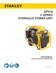
GT18B01 / GT18B02
HYDRAULIC
POWER UNIT
USER MANUAL
Safety, Operation and Maintenance
© 2014 Stanley Black & Decker, Inc.
New Britain, CT 06053
U.S.A.
65465 2/2015 Ver. 16
DECLARATION OF CONFORMITY
DECLARATION OF CONFORMITY
ÜBEREINSTIMMUNGS-ERKLARUNG
DECLARATION DE CONFORMITE CEE
DECLARACION DE CONFORMIDAD
DICHIARAZIONE DI CONFORMITA
Hydraulic Tools
______________________________________________________________________
I, the undersigned:
Ich, der Unterzeichnende:
Je soussigné:
El abajo firmante:
lo sottoscritto:
Weisbeck, Andy
Surname and First names/Familiennname und Vornamen/Nom et prénom/Nombre y apellido/Cognome e nome
hereby declare that the equipment specified hereunder:
bestätige hiermit, daß erklaren Produkt genannten Werk oder Gerät:
déclare que l’équipement visé ci-dessous:
Por la presente declaro que el equipo se especifica a continuación:
Dichiaro che le apparecchiature specificate di seguito:
1.
Category:
Kategorie:
Catégorie:
Categoria:
Categoria:
Hydraulic Power Unit
2.
Make/Marke/Marque/Marca/Marca
Stanley
3.
Type/Typ/Type/Tipo/Tipo:
4.
Serial number of equipment:
Seriennummer des Geräts:
Numéro de série de l’équipement:
Numero de serie del equipo:
Matricola dell´attrezzatura:
GT18B01, GT18B07
All
Has been manufactured in conformity with
Wurde hergestellt in Übereinstimmung mit
Est fabriqué conformément
Ha sido fabricado de acuerdo con
E’ stata costruita in conformitá con
Directive/Standards
Richtlinie/Standards
Directives/Normes
Directriz/Los Normas
Direttiva/Norme
No.
Nr
Numéro
No
n.
Approved body
Prüfung durch
Organisme agréé
Aprobado
Collaudato
EN ISO
12100:2010
Noise Directive
ISO
2000/14/EC:2005
3744:2010
Machinery Directive
2006/42/EC:2006
Self
Self
AkustikNet (Notified body ID 1585)
Bagsvard Hovedgade 141, 2880 Bagsvard, Denmark
Certificate #863/2011/001
Self
6.
Special Provisions:
None
Spezielle Bestimmungen:
Dispositions particulières:
Provisiones especiales:
Disposizioni speciali:
8.
Representative in the Union: Patrick Vervier, Stanley Dubuis 17-19, rue Jules Berthonneau-BP 3406 41034 Blois Cedex, France.
Vertreter in der Union/Représentant dans l’union/Representante en la Union/Rappresentante presso l’Unione
7. Measurements:
Messungen
Mesures
Mediciones
Misurazioni
Done at/Ort/Fait à/Dado en/Fatto a Stanley Hydraulic Tools, Milwaukie, Oregon USA
Signature/Unterschrift/Signature/Firma/Firma
Position/Position/Fonction/Cargo/Posizione
2 ► GT18B01-B02 User Manual
Director of Product Development
Measured Sound Power Level 99 LwA
Guaranteed Sound Power Level 101 LwA
Measured in accordance to Directive 2000/14/EC,
Noise related value: Installed Power 13,25 kW
Date/Datum/le/Fecha/Data
7-21-11
TABLE OF CONTENT
DECLARATION OF CONFORMITY........................................................................................................................2
SAFETY SYMBOLS................................................................................................................................................4
SAFETY PRECAUTIONS.......................................................................................................................................5
TOOL STICKERS & TAGS......................................................................................................................................6
HYDRAULIC HOSE TYPES....................................................................................................................................7
HOSE RECOMMENDATIONS................................................................................................................................8
HTMA REQUIREMENTS........................................................................................................................................9
OPERATION.........................................................................................................................................................10
FOR 5 GPM OPERATION...................................................................................................................................12
FOR 8 GPM OPERATION...................................................................................................................................12
COLD WEATHER STARTUP..............................................................................................................................13
SHUTDOWN.......................................................................................................................................................13
ROUTINE MAINTENANCE...................................................................................................................................14
PROGRAMMABLE CONTROLLER......................................................................................................................15
CHECKING PERFORMANCE CONTROL™ (ELECTRONIC GOVERNOR-STATIC CHECK)............................ 15
FAULT CODES......................................................................................................................................................15
TESTING & TROUBLESHOOTING......................................................................................................................17
GENERAL.............................................................................................................................................................17
TESTING THE HYDRAULIC CIRCUIT.................................................................................................................17
TROUBLESHOOTING..........................................................................................................................................18
SPECIFICATIONS.................................................................................................................................................19
BRIGGS ENGINE ASSEMBLY..............................................................................................................................20
BRIGGS ENGINE PARTS LIST............................................................................................................................21
FUEL TANK & CAP...............................................................................................................................................22
FRAME PARTS.....................................................................................................................................................23
HOSES, FITTINGS & CLAMPS............................................................................................................................24
MAIN POWER UNIT WIRING HARNESS.............................................................................................................25
IMPORTANT
To fill out a Product Warranty Validation form, and for information on your warranty,
visit Stanleyhydraulics.com and select the Company tab, Warranty.
(NOTE: The warranty Validation record must be submitted to validate the warranty).
SERVICING: This manual contains safety, operation, and routine maintenance instructions. Servicing of hydraulic
tools, other than routine maintenance, must be performed by an authorized and certified dealer. Please read the
following warning.
WARNING
SERIOUS INJURY OR DEATH COULD RESULT FROM THE IMPROPER REPAIR OR
SERVICE OF THIS TOOL.
REPAIRS AND / OR SERVICE TO THIS TOOL MUST ONLY BE DONE BY AN
AUTHORIZED AND CERTIFIED DEALER.
For the nearest authorized and certified dealer, call Stanley Hydraulic Tools at the number listed on the back of this
manual and ask for a Customer Service Representative.
GT18B01-B02 User Manual ◄ 3
SAFETY SYMBOLS
Safety symbols and signal words, as shown below, are used to emphasize all operator, maintenance and repair actions which, if not strictly followed, could result in a life-threatening situation, bodily injury or damage to equipment.
This is the safety alert symbol. It is used to alert you to potential personal injury
hazards. Obey all safety messages that follow this symbol to avoid possible
injury or death.
DANGER
This safety alert and signal word indicate an imminently hazardous situation
which, if not avoided, will result in death or serious injury.
WARNING
This safety alert and signal word indicate a potentially hazardous situation
which, if not avoided, could result in death or serious injury.
CAUTION
This safety alert and signal word indicate a potentially hazardous situation
which, if not avoided, could result in death or serious injury.
CAUTION
This signal word indicates a potentially hazardous situation which, if not avoided, may result in property damage.
NOTICE
This signal word indicates a situation which, if not avoided, will result in damage
to the equipment.
IMPORTANT
This signal word indicates a situation which, if not avoided, may result in damage to the equipment.
Always observe safety symbols. They are included for your safety and for the protection of the tool.
LOCAL SAFETY REGULATIONS
Enter any local safety regulations here. Keep these instructions in an area accessible to the operator and maintenance personnel.
4 ► GT18B01-B02 User Manual
SAFETY PRECAUTIONS
Tool operators and maintenance personnel must always
comply with the safety precautions given in this manual
and on the stickers and tags attached to the equipment.
These safety precautions are given for your safety. Review them carefully before operating the tool and before
performing general maintenance or repairs.
Supervising personnel should develop additional
precautions relating to the specific work area and local
safety regulations. If so, place the added precautions in
the space provided on page 5.
In addition to this manual, read and understand safety
and operating instructions in the Engine Operation
Manual furnished with the power unit.
The Hydraulic Power Unit will provide safe and dependable service if operated in accordance with the
instructions given in this manual. Read and understand
this manual and any stickers and tags attached to the
Power Unit. Failure to do so could result in personal
injury or equipment damage.
• Be sure all hoses are connected for correct flow
direction to and from the tool being used.
• Do not inspect hoses and fittings for leaks by using
bare hands. “Pin-hole” leaks can penetrate the skin.
• NEVER OPERATE THE POWER UNIT IN A
CLOSED SPACE. Inhalation of engine exhaust can be
fatal.
• Do not operate a damaged, improperly adjusted
power unit.
• Never wear loose clothing that can get entangled in
the working parts of the power unit.
• Keep all parts of your body away from the working
parts of the power unit.
• Keep clear of hot engine exhaust.
• Do not add fuel to the power unit while the power unit
is running or is still hot.
• Do not operate the power unit if gasoline odor is
present.
• Operator must start in a work area without bystanders. The operator must be familiar with all prohibited
work areas such as excessive slopes and dangerous
terrain conditions.
• Do not use flammable solvents around the power unit
engine.
• Do not operate the power unit within 3.3 ft/1 m of
buildings, obstructions or flammable objects.
• Establish a training program for all operators to ensure safe operation.
• Do not reverse tool rotation direction by changing
fluid flow direction.
• Do not operate the power unit unless thoroughly
trained or under the supervision of an instructor.
• Allow power unit engine to cool before storing in an
enclosed space.
• Always wear safety equipment such as goggles, ear,
head protection, and safety shoes at all times when
operating the power unit and a hydraulic tool.
• Always keep critical tool markings, such as labels
and warning stickers legible.
• Do not inspect or clean the power unit while it is
running. Accidental engagement of the unit can cause
serious injury.
• To avoid personal injury or equipment damage, all
tool repair, maintenance and service must only be performed by authorized and properly trained personnel.
• Always use hoses and fittings rated at 2500 psi/172
bar with a 4 to 1 safety factor. Be sure all hose connections are tight. GT18B01-B02 User Manual ◄ 5
TOOL STICKERS & TAGS
28322 CE Decal
GT18B01 Only
73306
Lift Point Decal
GT18B01 Only
66653 Guaranteed
Sound Power Level
Decal
GT18B01 Only
DANGER
CHOKE
PULL TO START
PUSH TO RUN
62302 Power Unit Dash Decal
62300 Single Circuit Decal
6 ► GT18B01-B02 User Manual
HOSE TYPES
The rated working pressure of the hydraulic hose must be equal to or higher than the relief valve setting on the hydraulic system. There are three types of hydraulic hose that meet this requirement and are authorized for use with
Stanley Hydraulic Tools. They are:
Certified non-conductive — constructed of thermoplastic or synthetic rubber inner tube, synthetic fiber braid
reinforcement, and weather resistant thermoplastic or synthetic rubber cover. Hose labeled certified nonconductive is the only hose authorized for use near electrical conductors.
Wire-braided (conductive) — constructed of synthetic rubber inner tube, single or double wire braid reinforcement, and weather resistant synthetic rubber cover. This hose is conductive and must never be used near
electrical conductors.
Fabric-braided (not certified or labeled non-conductive) — constructed of thermoplastic or synthetic rubber inner tube, synthetic fiber braid reinforcement, and weather resistant thermoplastic or synthetic rubber cover. This
hose is not certified non-conductive and must never be used near electrical conductors.
HOSE SAFETY TAGS
To help ensure your safety, the following DANGER tags are attached to all hose purchased from Stanley Hydraulic
Tools. DO NOT REMOVE THESE TAGS.
If the information on a tag is illegible because of wear or damage, replace the tag immediately. A new tag may be
obtained from your Stanley Distributor.
D A N G E R
D A N G E R
1.
FAILURE TO USE HYDRAULIC HOSE LABELED AND CERTIFIED AS NON-CONDUCTIVE
WHEN USING HYDRAULIC TOOLS ON OR NEAR ELECTRIC LINES MAY RESULT IN
DEATH OR SERIOUS INJURY.
FOR PROPER AND SAFE OPERATION MAKE SURE THAT YOU HAVE BEEN PROPERLY TRAINED IN CORRECT PROCEDURES REQUIRED FOR WORK ON OR AROUND
ELECTRIC LINES.
2.
BEFORE USING HYDRAULIC HOSE LABELED AND CERTIFIED AS NON-CONDUCTIVE
ON OR NEAR ELECTRIC LINES. WIPE THE ENTIRE LENGTH OF THE HOSE AND FITTING WITH A CLEAN DRY ABSORBENT CLOTH TO REMOVE DIRT AND MOISTURE AND
TEST HOSE FOR MAXIMUM ALLOWABLE CURRENT LEAKAGE IN ACCORDANCE WITH
SAFETY DEPARTMENT INSTRUCTIONS.
3.
DO NOT EXCEED HOSE WORKING PRESSURE OR ABUSE HOSE. IMPROPER USE
OR HANDLING OF HOSE COULD RESULT IN BURST OR OTHER HOSE FAILURE.
KEEP HOSE AS FAR AWAY AS POSSIBLE FROM BODY AND DO NOT PERMIT DIRECT
CONTACT DURING USE. CONTACT AT THE BURST CAN CAUSE BODILY INJECTION
AND SEVERE PERSONAL INJURY.
4.
HANDLE AND ROUTE HOSE CAREFULLY TO AVOID KINKING, ABRASION, CUTTING, OR
CONTACT WITH HIGH TEMPERATURE SURFACES. DO NOT USE IF KINKED. DO NOT
USE HOSE TO PULL OR LIFT TOOLS, POWER UNITS, ETC.
5.
CHECK ENTIRE HOSE FOR CUTS CRACKS LEAKS ABRASIONS, BULGES, OR DAMAGE TO COUPLINGS IF ANY OF THESE CONDITIONS EXIST, REPLACE THE HOSE
IMMEDIATELY. NEVER USE TAPE OR ANY DEVICE TO ATTEMPT TO MEND THE HOSE.
6.
AFTER EACH USE STORE IN A CLEAN DRY AREA.
SEE OTHER SIDE
SIDE 1
SEE OTHER SIDE
(Shown smaller than actual size)
DO NOT REMOVE THIS TAG
DO NOT REMOVE THIS TAG
THE TAG SHOWN BELOW IS ATTACHED TO “CERTIFIED NON-CONDUCTIVE” HOSE
SIDE 2
D A N G E R
D A N G E R
1.
DO NOT USE THIS HYDRAULIC HOSE ON OR NEAR ELECTRIC LINES. THIS HOSE IS
NOT LABELED OR CERTIFIED AS NON-CONDUCTIVE. USING THIS HOSE ON OR NEAR
ELECTRICAL LINES MAY RESULT IN DEATH OR SERIOUS INJURY.
5.
CHECK ENTIRE HOSE FOR CUTS CRACKS LEAKS ABRASIONS, BULGES, OR DAMAGE TO
COUPLINGS IF ANY OF THESE CONDITIONS EXIST, REPLACE THE HOSE IMMEDIATELY.
NEVER USE TAPE OR ANY DEVICE TO ATTEMPT TO MEND THE HOSE.
2.
FOR PROPER AND SAFE OPERATION MAKE SURE THAT YOU HAVE BEEN PROPERLY
TRAINED IN CORRECT PROCEDURES REQUIRED FOR WORK ON OR AROUND ELECTRIC LINES.
6.
AFTER EACH USE STORE IN A CLEAN DRY AREA.
3.
DO NOT EXCEED HOSE WORKING PRESSURE OR ABUSE HOSE. IMPROPER USE OR
HANDLING OF HOSE COULD RESULT IN BURST OR OTHER HOSE FAILURE. KEEP HOSE
AS FAR AWAY AS POSSIBLE FROM BODY AND DO NOT PERMIT DIRECT CONTACT
DURING USE. CONTACT AT THE BURST CAN CAUSE BODILY INJECTION AND SEVERE
PERSONAL INJURY.
4.
HANDLE AND ROUTE HOSE CAREFULLY TO AVOID KINKING, CUTTING, OR CONTACT
WITH HIGH TEMPERATURE SURFACES. DO NOT USE IF KINKED. DO NOT USE HOSE TO
PULL OR LIFT TOOLS, POWER UNITS, ETC.
DO NOT REMOVE THIS TAG
DO NOT REMOVE THIS TAG
THE TAG SHOWN BELOW IS ATTACHED TO “CONDUCTIVE” HOSE.
SEE OTHER SIDE
SEE OTHER SIDE
SIDE 1
SIDE 2
(Shown smaller than actual size)
GT18B01-B02 User Manual ◄ 7
8 ► GT18B01-B02 User Manual
All hydraulic hose must meet or exceed
specifications as set forth by SAE J517.
All hydraulic hose must have at least a rated
minimum working pressure equal to the maximum hydraulic system relief valve setting.
This chart is intended to be used for hydraulic
tool applications only based on Stanley Hydraulic Tools tool operating requirements and
should not be used for any other applications.
The chart to the right shows recommended
minimum hose diameters for various hose
lengths based on gallons per minute (gpm)/
liters per minute (lpm). These recommendations are intended to keep return line pressure
(back pressure) to a minimum acceptable level to ensure maximum tool performance.
Tool to Hydraulic Circuit Hose
Recommendations
15-34
MM
Inside Diameter
INCH
USE
(Press/Return)
PSI
up to 10
up to 3
3/8
10
Both
2250
49-60
13-16
FLOW >>>
RETURN
<<< FLOW
PRESSURE
26-100
up to 25
100-200
51-100
up to 50
100-300
51-100
up to 50
26-100
up to 25
8-30
up to 8
30-60
15-30
up to 15
30-90
15-30
up to 15
7.5-30
up to 7.5
Figure 1. Typical Hose Connections
49-60
38-49
10-13
13-16
19-40
5-10.5
38-49
19-40
5-10.5
10-13
19-40
5-10.5
38-49
15-23
10-13
15-23
4-6
19
25.4
16
19
19
25.4
5/8
3/4
3/4
1
19
3/4
1
16
3/4
16
19
3/4
5/8
16
5/8
5/8
16
13
13
10
5/8
1/2
1/2
3/8
Return
Pressure
Return
Pressure
Return
Pressure
Return
Pressure
Both
Return
Pressure
Both
Both
Both
Both
2500
2500
2500
2500
2500
2500
2500
2500
2500
2500
2500
2500
2500
2500
2500
175
175
175
175
175
175
175
175
175
175
175
175
175
175
175
155
BAR
Min. Working Pressure
Certified Non-Conductive Hose - Fiber Braid - for Utility Bucket Trucks
METERS
Hose Lengths
FEET
Conductive Hose - Wire Braid or Fiber Braid -DO NOT USE NEAR ELECTRICAL CONDUCTORS
4-6
4-9
LPM
Oil Flow
GPM
HOSE RECOMMENDATIONS
HTMA / EHTMA REQUIREMENTS
HTMA / EHTMA REQUIREMENTS
HTMA
HYDRAULIC SYSTEM REQUIREMENTS
TYPE I
Nominal Operating Pressure
(at the power supply outlet)
4-6 gpm
(15-23 lpm)
1500 psi
(103 bar)
TOOL TYPE
TYPE II
TYPE RR
7-9 gpm
(26-34 lpm)
1500 psi
(103 bar)
9-10.5 gpm
(34-40 lpm)
1500 psi
(103 bar)
System relief valve setting
(at the power supply outlet)
2100-2250 psi
(145-155 bar)
2100-2250 psi
(145-155 bar)
2200-2300 psi
(152-159 bar)
2100-2250 psi
(145-155 bar)
Maximum back pressure
(at tool end of the return hose)
250 psi
(17 bar)
250 psi
(17 bar)
250 psi
(17 bar)
250 psi
(17 bar)
Measured at a max. fluid viscosity of:
(at min. operating temperature)
400 ssu*
400 ssu*
400 ssu*
400 ssu*
(82 centistokes) (82 centistokes) (82 centistokes) (82 centistokes)
Temperature: Sufficient heat rejection
capacity to limit max. fluid temperature to:
(at max. expected ambient temperature)
140° F
(60° C)
Flow Range
140° F
(60° C)
140° F
(60° C)
TYPE III
11-13 gpm
(42-49 lpm)
1500 psi
(103 bar)
140° F
(60° C)
3 hp
5 hp
6 hp
7 hp
Min. cooling capacity at a temperature
(2.24 kW)
(3.73 kW)
(5.22 kW)
(4.47 kW)
difference of between ambient and fluid
40° F
40° F
40° F
40° F
temps
(22° C)
(22° C)
(22° C)
(22° C)
NOTE:
Do not operate the tool at oil temperatures above 140° F (60° C). Operation at higher temperatures can cause operator
discomfort at the tool.
Filter
Min. full-flow filtration
Sized for flow of at least:
(For cold temp. startup and max.
dirt-holding capacity)
25 microns
30 gpm
(114 lpm)
Hydraulic fluid Petroleum based
(premium grade, anti-wear, non-conductive)
Viscosity (at min. and max. operating temps)
100-400 ssu*
25 microns
30 gpm
(114 lpm)
25 microns
30 gpm
(114 lpm)
100-400 ssu*
100-400 ssu*
(20-82 centistokes)
25 microns
30 gpm
(114 lpm)
100-400 ssu*
NOTE:
When choosing hydraulic fluid, the expected oil temperature extremes that will be experienced in service determine the
most suitable temperature viscosity characteristics. Hydraulic fluids with a viscosity index over 140 will meet the requirements
over a wide range of operating temperatures.
*SSU = Saybolt Seconds Universal
EHTMA
HYDRAULIC SYSTEM
REQUIREMENTS
CLASSIFICATION
B
C
D
Nominal Operating Pressure
(at the power supply outlet)
3.5-4.3 gpm
(13.5-16.5 lpm)
1870 psi
(129 bar)
4.7-5.8 gpm
(18-22 lpm)
1500 psi
(103 bar)
7.1-8.7 gpm
(27-33 lpm)
1500 psi
(103 bar)
9.5-11.6 gpm
(36-44 lpm)
1500 psi
(103 bar)
11.8-14.5 gpm
(45-55 lpm)
1500 psi
(103 bar)
System relief valve setting
(at the power supply outlet)
2495 psi
(172 bar)
2000 psi
(138 bar)
2000 psi
(138 bar)
2000 psi
(138 bar)
2000 psi
(138 bar)
Flow Range
NOTE: These are general hydraulic system requirements. See tool specification page for tool specific requirements
GT18B01-B02 User Manual ◄ 9
OPERATION
PREPARATION FOR USE
Do not operate the power unit until you have read the
engine operating and maintenance instructions manual
furnished with the unit.
4. HYDRAULIC FLUID RECOMMENDED HYDRAULIC OILS
Below is a list of recommended oils by brand.
Brand
Biodegradable
Description
1. ENGINE CRANKCASE OIL LEVEL CITGO
No
Hydurance AW32
Always check the oil level before starting the engine. Make
sure the oil level is at the FULL MARK on the dipstick. Do
not overfill. Use detergent oil classified "For Service SE,
SF, SG" as specified in the engine operating and maintenance manual. See engine manual for oil viscosity grade.
AMS Oil
No
HVH 32
Exxon Mobil
No
Univis HVI26*
Exxon Mobil
No
DTE 10 Excel
Shell
No
S2 V 32
Chevron
No
Rando HDZ 32
Conoco Phillips
No
Unax AW-WR-32
Clarion (CITGO)
Yes
Green Bio 32
Exxon Mobil
Yes
EAL 224H
Chevron
Yes
Clarity AW32
Terresolve
Yes
Envirologic 132
Shell
Yes
Naturelle HF-E-32
2. SPARK PLUG
On power units equipped with Briggs & Stratton Engines,
ONLY Champion RC12YC or equivalent can be used.
Incorrect type spark plugs can produce radio frequency
interference that will corrupt and damage the controller.
Failure to use the correct spark plug could result in a warranty that will not be considered.
*Recommended for extreme cold temperatures
3. ENGINE FUEL LEVEL
Check the fuel level. If low, fill with un-leaded gasoline with
a minimum of 85 octane.
5. HYDRAULIC CONNECTIONS
The recommended hose length is 25 ft/8 m with a 1/2
inch/12.7 mm inside diameter. The hoses must have a
working pressure rating of at least 2500 psi/175 bar. Each
hose end must have male thread ends compatible with
H.T.M.A. (HYDRAULIC TOOL MANUFACTURERS ASSOCIATION) quick disconnect fittings (NPT type threads).
(See Figure 2.)
Figure 1. Control Panel
Facing the control panel, the bottom male quick disconnect
fitting is the PRESSURE FLUID OUT fitting. The top female
quick disconnect fitting is the RETURN FLUID IN fitting.
10 ► GT18B01-B02 User Manual
OPERATION
QUICK DISCONNECT COUPLERS
H.T.M.A. approved quick disconnect couplings are installed
to hydraulic hoses so that the direction of oil flow is always
from the male to the female quick disconnect as shown in
figure 2. Quick disconnect couplings and hose fittings are
selected so that additional fittings such as reducer or adapter fittings are not required.
If adapter fittings are used, they must be approved steel
hydraulic fittings meeting a minimum operating pressure
rating of 2500 psi/172 bar. Do not use galvanized pipe fittings or black pipe fittings.
Use thread tape or pipe joint compound when installing
quick disconnect couplings to hose or tool fittings. Follow
the instructions furnished with the selected thread sealant.
DO NOT OVERTIGHTEN THE FITTINGS.
CONTROL
PANEL
CONTROL
PANEL
Figure 2
RETURN
PRESSURE
H.T.M.A. 1/2 INCH FEMALE QUICK DISCONNECT COUPLER
H.T.M.A. 1/2 INCH MALE
QUICK DISCONNECT
COUPLER
1/2 INCH MALE PIPE HOSE END
6. BATTERY
1/2 INCH I.D. HOSE, 25 FT
LONG WITH 2500 PSI/
172 BAR RATING AND
4 TO 1 SAFETY FACTOR
NOTICE
Do not charge the battery with a standard automotive
battery charger. This type of charger produces a
charging amperage higher than 2 amps. Charging
the battery at higher than 2 amps will damage the
battery.
RETURN
PRESSURE
1/2 INCH MALE PIPE HOSE END
NOTICE
H.T.M.A. 1/2 INCH FEMALE QUICK DISCONNECT COUPLER
If the engine runs out of gas or dies during operation
and the ignition switch is left in the ON or RUN
position, this could drain the battery. Make sure the
ignition switch is returned to the OFF position.
H.T.M.A. 1/2 INCH MALE
QUICK DISCONNECT
COUPLER
ADAPTER, 3/8 INCH MALE PIPE x
-8 SAE O-RING
PRESSURE
TOOL
RETURN
GT18B01-B02 User Manual ◄ 11
OPERATION
CONTROLS
This unit is equipped with an advanced proportional engine
control system. It provides a means of controlling engine
speed by adjusting the fuel control lever with an actuator.
The Power Unit provides one circuit, with an oil flow of 5
gpm/19 lpm up to 2000 psi/140 bar or 8 gpm/30 lpm up
to 2000 psi/140 bar with a factory-programmed electronic
governed engine throttle.
throttle control
switch
flow selector
switch
ignition switch
Figure 3. Control Panel
One hydraulic tool can be connected to the tool circuit.
The circuit is activated by turning the flow control switch to
either the 5 gpm/19 lpm or 8 gpm/30 lpm setting.
At times it may be neccessary to reset the controller. This
could happen if a fault occurs in the controller. For example, excessive engine speed. If a fault does occur the
power unit will return to an idle and the operator will have
no control of the unit. To reset the controller, simply turn off
the power unit and restart it.
STARTUP
Before starting the engine make sure the flow selector
switch is in the OFF position.
Note:
The power unit will not start if the flow control switch is
not in the "OFF" position.
Pull choke knob out and move the Throttle Control Switch
to the auto-idle-off or the auto-idle-on position, whichever
mode of operation the operator prefers. Ensure the flow
selector switch is in the OFF position.
Turn the Ignition Switch to the START position. After the
engine starts, release the switch.
THROTTLE CONTROL
The throttle control permits the operator to select one of 2
operating modes after the engine has warmed up. When
starting the engine, make sure the flow selector switch is
in the off position. The throttle control switch can be set in
either the auto-idle-on or auto-idle-off positions.
Gradually push in the choke knob as the engine begins to
idle smoothly.
AUTO-ON
When the throttle control switch is in the "AUTO-ON" position, the oil flow is regulated automatically when the trigger
on the tool is activated. When the tool is not being used the
engine will return to idle automatically, after a 10 second
delay.
FOR 5 GPM OPERATION
This setting will produce 5 gpm/19 lpm or 8 gpm/30 lpm
depending on which postion the operator has selected with
the flow selector switch.
When finished operating the tool, move the flow selector
switch to the OFF position.
AUTO-OFF
When the throttle control switch is in the "AUTO-OFF" position, the engine speed is held to maintain 5 gpm/19 lpm or
8 gpm/30 lpm depending on which position the operator
has selected with the flow selector switch. When a tool is
not being used the engine will not return to idle until either
the flow selector switch is turned to the off position or the
throttle control switch is turned to auto-on.
Note:
It may be necessary to reset the Controller.
12 ► GT18B01-B02 User Manual
Allow the engine to warm up.
Connect hoses and the tool as desrcribed in this manual.
For 5 gpm operation, select mode of operation with the
Throttle Control switch, either auto-idle-on or the auto-idleoff position. Move the flow selector switch to the 5 gpm
position.
FOR 8 GPM OPERATION
For 8 gpm operation, select mode of operation with the
Throttle Control Switch, either auto-idle-on or the auto-idleoff position. Move the flow selector switch to the 8 gpm
position.
When finished operating the tool, move the flow selector
switch to the OFF position.
OPERATION
COLD WEATHER STARTUP
1. Use the procedures described under "STARTUP" and
then follow the procedure below.
2. Hydraulic fluids are thicker in cold weather. Therefore,
it is recommended that the engine be run at low idle long
enough to bring the fluid temperature up to a minimum of
50°F/10°C.
3. If the tools and tool hoses are cold, it is recommended
to allow hydraulic fluid to circulate through the tool hoses
until warm before using the tool.
SHUTDOWN
1. Ensure the flow selector switch in the OFF position
(center position).
2. Unless already at idle the power unit should return to
idle. This may take a few seconds for the unit to react due
to a built-in program delay.
3. Allow the engine to idle for approximately one minute
and move the Ignition Switch to the OFF position.
GT18B01-B02 User Manual ◄ 13
ROUTINE MAINTENANCE
ENGINE MAINTENANCE
Follow the maintenance schedule and general maintenance instructions in the engine maintenance and operation manual furnished with the power unit.
SPARK PLUG
On power units equipped with Briggs & Stratton Engines,
ONLY Champion RC12YC or equivalent can be used.
Incorrect type spark plugs can produce radio frequency
interference that will corrupt and damage the controller.
Failure to use the correct spark plug could result in a warranty that will not be considered.
HYDRAULIC SYSTEM MAINTENANCE
• Check hydraulic fluid level daily. Add fluid per specifications in this manual. (See "HYDRAULIC FLUID" under the
section titled "OPERATING INSTRUCTIONS".
• Remove condensed moisture from the hydraulic
fluid by pumping the hydraulic fluid into a 5 gal/20 l container through the pressure hose. Make sure the engine is
at idle when performing this procedure. When the hydraulic
reservoir is empty turn the engine off immediately.
• Allow the fluid to sit long enough for the water to settle to
the bottom of the container. Slowly pour the fluid back into
the hydraulic tank, avoiding the water at the bottom of the
container.
• Each day, check hydraulic lines and fittings for leaks,
kinks, etc. Do not use your hand to perform this check.
14 ► GT18B01-B02 User Manual
• Change the hydraulic filter element every 200 hours of
operation. Change more often if cold, moist or dusty conditions exist.
• Check oil cooler for debris. Remove debris with air pressure.
STORAGE
• Clean the unit thoroughly before storage. Do not use
water pressure.
• Always store the unit in a clean and dry facility.
• If the unit will be stored for a prolonged period (over 30
days), add a fuel additive to the fuel tank to prevent the fuel
from gumming. Run engine for a short period to circulate
the additive.
• Replace crankcase oil with new oil.
PROGRAMMABLE CONTROLLER
The Stanley programmable controller is an electronic
engine governor that provides a means of controlling and
limiting engine speed by adjusting the fuel control lever with
a proportional actuator.
The controller is factory preset and has no manual adjustments.
a. If actuator does not move it is defective. (Replace).
b. If actuator moves throttle to wide-open position, the
module is defective. (Replace).
FAULT CODES
The Stanley controller is capable of identifying certain fault
conditions and alerting the user to them. A flashing LED
indicates the fault conditions. The current fault code list is
shown on the following page. Please note the following:
A flashing LED
indicates the
fault condition
1. When power is first applied to the controller, the LED will
flash just once for one second to indicate that the LED is
working.
2. If there are multiple faults, the LED will flash them all
in sequence. Count the flash codes to determine the fault
conditions or connect the Calibration Tool to observe the
fault conditions. (Use the “Display Faults” option under the
Monitor Menu.)
TROUBLESHOOTING GUIDELINES
Please follow the checklist below to troubleshoot your Stanley controller.
1. Check battery voltage for stability and correct value. The
LED will turn on for one second when the controller 4500 is
first powered up.
3. If there are no faults, the LED will flash once at reset
and from then on indicate the detection of engine speed. A
continuous ON LED indicates that a valid engine speed is
being sensed.
4. The controller will attempt to shut down for some faults
and will not permit starting after reset with faults 1, 5 and 8.
2. Check the actuator linkage for binding and backlash.
Checking Performance Control™ (Electronic
Governor-Static Check)
To determine whether a governor problem is being caused
by the actuator or the control module, perform the following
static check exactly in order shown.
A pair of jumper wires and a known good 12-volt battery is
required.
1. Disconnect red and green wires from the control module
to actuator.
2. Attach jumper wires from battery to RED and GREEN
wires to actuator.
a. Attach 12 volt + (positive) to RED wire.
b. Attach 12 volt – (negative) to GREEN wire.
3. Actuator should move throttle lever to wide open position.
GT18B01-B02 User Manual ◄ 15
FAULT CODES
FLASH
ENGINE
CODE
FAULT
SHUTDOWN
CORRECTIVE ACTION
1
APECS unit not calibrated
yes
Have engine serviced by an Authorized Stanley Dealer.
2
Engine speed excessive
yes
Have engine serviced by an Authorized Stanley Dealer.
3
Engine speed unusually low
yes
Have engine serviced by an Authorized Stanley Dealer.
4
Engine shutdown due to engine
yes
Have engine serviced by an Authorized Stanley Dealer.
protection input
5
Factory settings lost
yes
Have engine serviced by an Authorized Stanley Dealer.
6
External pot out-of-range
no
Have engine serviced by an Authorized Stanley Dealer.
7
Accelerator position / idle
no
Have engine serviced by an Authorized Stanley Dealer.
switch conflict
8
Controller unit failed
yes
Have engine serviced by an Authorized Stanley Dealer.
9
Limiting excessive
no
Have engine serviced by an Authorized Stanley Dealer.
10
Engine speed input
no
(Active only in Auto crank mode).
actuator current
signal missing
Check speed sensor wiring.
Check starter motor.
11
Auto crank unable to
12
Auxiliary output is shorted
no
Check fuel.
no
Check the lamp or relay hooked to the output. If fault is
start engine
still present, have engine serviced by an authorized
Stanley Dealer.
13
Auxiliary output #2 is shorted
no
Check the lamp or relay hooked to the output. If fault is
still present, have engine serviced by an authorized
Stanley dealer.
14
Actuator disconnected or
open circuit
16 ► GT18B01-B02 User Manual
no
Check actuator wiring and actuator resistance.
Resistance should be less than 10 ohms.
TESTING & TROUBLESHOOTING
GENERAL
Tests and adjustments should be performed periodically to
ensure the power unit is operating at maximum efficiency.
Stanley Circuit Tester (part number 04182) is recommended. This tester can be used to isolate problems in both the
engine and hydraulic system prior to any power unit disassembly.
TESTING THE HYDRAULIC CIRCUIT
The following tests can be performed to ensure that the
hydraulic pump is supplying the correct flow and pressure
and that the system relief valve is operating properly.
During these tests, make sure the engine is warm and operating smoothly. If test results are not as specified, refer to
the troubleshooting table in this section for possible causes.
9. At 2100-2200 psi/148-155 bar, the relief valve should
begin to open. The pressure at which the relief valve just
begins to open is commonly referred to as the "cracking
pressure". At the "cracking pressure," the flow rate should
start to drop because the relief valve is allowing fluid to bypass to the hydraulic reservoir. The "cracking pressure" is
preset at the factory and if it is not within the above range,
the relief valve must be re-set as follows:
a. The relief valve is located on the right side of the unit just
behind the dash panel. It protrudes out from the manifold
assembly. Use a open end or box end wrench to loosen the
nut on the relief valve.
b. Use an Allen wrench to adjust the relief valve. Turn
clockwise to raise the pressure and counterclockwise to
reduce the pressure.
c. Tighten the nut and retest.
Testing The 5 gpm htma type I circuit
or the 8 gpm type II circuit
To test the circuit, proceed as follows:
1. Set the flow selector switch to the OFF (center) position.
2. Set the throttle control switch to AUTO-OFF position.
3. Connect the Stanley Circuit Tester across two hose ends
(where the tool would normally be connected).
4. Fully open the tester restrictor valve (counterclockwise).
5. Start the engine and allow it to run until warm.
6. Switch the flow selector switch to 5 or 8 gpm depending
on which flow you are testing.
7. With the engine at the programed speed, the test flow
gauge should read 4-6 gpm/15-23 lpm or 7-9 gpm/26.5-34
lpm.
8. Slowly turn the restrictor valve clockwise while watching the pressure gauge. The flow rate should stay at 4-6
gpm/15-23 lpm or 7-9 gpm/26.5-34 lpm as the pressure
gauge reaches 2100-2200 psi/148-155 bar.
GT18B01-B02 User Manual ◄ 17
TROUBLESHOOTING
PROBLEM
ENGINE WILL NOT START.
CAUSE
REMEDY
FLOW SELECTOR SWITCH NOT IN THE OFF POSITION.
MAKE SURE THE FLOW SELECTOR SWITCH IS IN
THE OFF POSITION WHEN STARTING.
BATTERY NOT CONNECTED.
ATTACH BATTERY CABLES, CHECK WIRES.
WEAK BATTERY.TEST BATTERY, CHARGE OR REPLACE.
NO FUEL.ADD FUEL.
FUEL FILTER PLUGGED.REPLACE FUEL FILTER.
DEFECTIVE SPARK PLUGS.
FLUID BLOWING OUT OF FLUID RESERVOIR VENT.
HYDRAULIC TANK OVERFILLED.
REMOVE PLUGS, CHECK GAP, CLEAN OR REPLACE.
CORRECT THE FLUID LEVEL.
PUMP SUCTION LEAK.
CHECK SUCTION CONNECTIONS. TIGHTEN IF
NECESSARY.
HYDRAULIC TOOL WON'T OPERATE FLOW SELECTOR SWITCH NOT SWITCHED ON.
CHECK THAT THE FLOW SELECTOR SWITCH
IS SET TO 5 OR 8 GPM.
INCORRECT HOSE CONNECTION
MAKE SURE THE TOOL HOSE CIRCUIT GOES
TO TOOL.FROM LEFT (PRESSURE) FITTING TO TOOL AND BACK TO
THE RIGHT FITTING (RETURN). FLUID ALWAYS FLOWS
FROM THE MALE TO FEMALE FITTINGS.
QUICK DISCONNECT FITTINGS
DETACH FROM HOSE, CONNECT SET
DEFECTIVE.TOGETHER AND CHECK FOR FREE FLOW.
HYDRAULIC FLUID LEVEL LOW.
CHECK FOR CORRECT FLUID LEVEL. FILL USING THE
RECOMMENDED FLUID.
PUMP COUPLING DEFECTIVE.
WITH THE ENGINE NOT RUNNING.
CHECK THE COUPLING BETWEEN THE PUMP
AND ENGINE THAT IT IS ENGAGED AND IS
NOT DAMAGED. CAUTION: KEEP HANDS
CLEAR OF ROTATING OBJECTS.
RELIEF VALVE STUCK OPEN.
ADJUST OR REPLACE VALVE.
SUCTION HOSE KINKED.
MAKE SURE SUCTION HOSE FROM FLUID RESERVOIR TO PUMP INLET HAS A SMOOTH CURVE.
SOLENOID NOT WORKING.
CHECK SOLENOID OPERATION AND ELECTRICAL
CONNECTIONS
.
TOOL IS DEFECTIVE.REFER TO TOOL MANUAL.
18 ► GT18B01-B02 User Manual
SPECIFICATIONS
Engine:.....................................................................................................................................................18 hp Briggs
Capacity................................................................................ One 5 gpm/19 lpm Circuit or One 8 gpm/30 lpm Circuit
Length:................................................................................................................................................ 36 in. / 91.4 cm
Width:.................................................................................................................................................. 23 in: / 58.4 cm
Height:............................................................................................................................................... 29.5 in. / 74.9cm
Weight (Wet): Single Circuit Briggs.................................................................................................330 lbs / 149.6 kg
Fuel Tank Capacity:............................................................................................................................ 5.5 gal. / 20.8 ltr
Estimated Gas Consumption Per Hour.................................................................................................... 1.3 gal / 4 ltr
Hydraulic Reservor Capacity:................................................................................................................... 3 gal. / 11 ltr
Relief Valve "crack" setting.............................................................................................................. 2100 psi / 145 bar
Max relief setting............................................................................................................................. 2500 psi / 172 bar
HTMA/EHTMA Category......................................................................................................................... Type 1 and 2
Nominal Pressure.............................................................................................................................. 1500 psi/103 bar
Max Pressure.................................................................................................................................... 2000 psi/138 bar
Guaranteed Sound Power Level.................................................................................................................... 101 dBA
Measured Sound Power Level......................................................................................................................... 99 dBA
Vibration Level........................................................................................................................................................ N/A
POWER UNITS,TRACHORSE & GAS/FUEL DRIVEN EQUIPMENT: A1. Federal Emission Component Compliance
40CFR part 1060.120 Stanley warrants all fuel system emission components for 2 years from the date of original purchase provided there has been no abuse, neglect, modifi cations, or improper maintenance.
Components covered. The emission-related warranty covers all components whose failure would increase the evaporative emissions. Your emission-related warranty does not cover components whose failure would not increase evaporative emissions. Coverage under this warranty extends only to the following parts; fuel tank, fuel cap, fuel hose and vapor
hose from the fuel tank to the engine and any connectors that are apart of the fuel system.
The equipment is designed, built, and equipped so it conforms at the time of sale to the ultimate purchaser and each
subsequent purchaser and is in compliance with 40 C.F.R. 1060.120 standards. The equipment is free from defects in
materials and workmanship that may keep it from meeting these requirements.
GT18B01-B02 User Manual ◄ 19
GT18B01 & B02 PARTS ILLUSTRATION
20 ► GT18B01-B02 User Manual
GT18B01 & B02 PARTS LIST
Ite m
Part No. Qty
No.
Description
Item
No.
Part No.
Qty
Description
1
36150
1
Muffler
36
60920
1
Grommet
1A
65456
1
Spark Arrester
37
73050
1
2
36151
1
Heat Shield
Fuel Tank (Important see note
on page 22 before ordering)
3
36152
2
Screw, Hex Washer
38
04303
1
Battery
4
59007
1
Briggs Engine (Includes Items
60 thru 70)
39
60921
1
Battery Cover
40
15476
1
Capscrew, 1/4-20 x 3/4
5
56656
1
Coupling
41
65068
1
Hex Flange Bolt
6
07819
1
Square Key
42
21714
2
Handle Bumper
7
07860
2
Capscrew, 3/8-16 x 1-1/4
43
58942
3
Hex Flange Bolt, 5/16 x 1-3/4
8
31765
1
Pressure Switch
44
01459
4
Lockwasher, 3/8
9
12787
4
Flange Nut
45
58975
2
Foot
10
24287
1
Clamp
46
18893
4
Flang Nut, 3/8-16
11
59076
1
Bushing
47
58976
4
Hex Flange Bolt, 3/8-16
12
20990
1
Key
48
31240
2
Retaining Ring
13
59103
1
Blower Hub
49
21318
2
Washer, 3/4
14
00111
3
Capscrew
50
59083
1
Blower Housing
15
40080
1
Filter Assy
51
56655
1
Pump Mount
16
43687
1
Capscrew
52
60919
1
Fuel Elbow
17
64937
1
Grip Plate
53
62385
2
Stud
18
51292
1
Std Thread Union
54
371503
1
Nut
19
17821
4
Button Head HS
55
62324
1
Heat Shield
20
60945
3
Washer, 1/4 in. ID
56
62292
2
Hex Washer Head Screws
21
15476
2
Capscrew, 1/2 -20 UNC
57
64991
1
Screw
22
59080
1
Front Grille
58
56709
1
Cable Clamp
23
59091
1
Cooler
59
65042
1
Rectifier Wire
69374
1
Throttle Lever
24
07860
2
Capscrew, 3/8
60
25
59077
1
Hydraulic Tank
61
59074
2
Hex Flange Bolt
26
62296
2
Weather Strip
62
68675
1
Angle Bracket Weldment
27
62303
1
Blower Wheel
63
68560
1
Rottary Actuator
28
59074
4
Hex Flange Bolt, 1/4 -20
64
68676
1
Actuator Bracket
29
72315
1
Engine Controller GT18B01
ONLY
66
69401
1
Wire Assembly
67
69281
4
Hex Socket Head Capscrew
69
69282
1
Hex Socket Head Capscrew
70
62181
1
Link Retainer
71
72451
3
Spring Hose Clamp
72
72571
1
Fuel Vapor Hose
73
72568
1
Barb
75
72317
2
Spring Hose Clamp
76
62289
1
Hose (Fuel)
72316
1
Engine Controller GT18B02
ONLY
30
40433
9
Hex Flange Bolt 5/16-18 x 1/2
31
58897
1
Frame Base Weldment
32
58918
2
Wheel & Tire
33
58917
1
Axle
34
04134
1
Pump, Single
35
71794
1
Fuel Cap (Important see note
on page 22 before ordering)
GT18B01-B02 User Manual ◄ 21
FUEL TANK & CAP
NOTE: When ordering a fuel tank (item
37) or fuel tank cap (item 35) DO NOT
MIX OLD STYLE TANK AND CAP
WITH NEW STYLE TANK AND CAP.
If you have a power unit and it was purchased prior to 2011 and need to replace the fuel tank or fuel tank cap, you
must purchase the same tank and cap
that came with your unit.
For example if you have a power unit
prior to 2011 do not purchase a new
style fuel tank, your engine will not be
equipped with a fuel vapor fitting.
The old style fuel cap is a vented cap,
while the new style fuel cap is not a
vented cap and venting is achieved thru
the vapor line.
The old style fuel tank has only one fuel
line coming from the tank to the engine.
The new style fuel tank has two lines
coming from the fuel tank to the engine,
one is the fuel line and the other is a fuel
vapor line.
P/N-73050
22 ► GT18B01-B02 User Manual
FRAME PARTS
See 12 Volt
Harness at Right
12 VOLT ACCESSORY NOT EQUIPPED ON ALL
MODELS
RECEPTACLE ASSY-64942
AVAILABLE AS AN ADD ON
TO STARTER
SOLENOID
RED
GROUND
25 Amp FUSE
BLACK
12-VOLT RECEPTACLE
Item
Part No. Qty
No.
Description
Item
Part No. Qty
No.
Description
1
370502
7
Capscrew, 5/16 in.-18 UNC
17
23530
2
Hex Flange Bolt, 3/8 in. -16
2
03906
7
Nylock Nut, 5/16 in. -18 UNC
18
58916
1
Handle Lock
3
62267
1
Handle, Rear Lift
19
62268
2
Lift Handle
4
58857
1
Coupler, Male 3/8 in., -8 SAE
20
59079
1
Cooler Guard
5
58856
1
Coupler, Female 3/8 in., -8 SAE
21
59095
2
Flange Nut, 1/4 in. -20
6
60962
2
Capscrew, 1/4 in. -20
22
7
59130
1
Manifold Assy, Single Circuit (includes items 23 thru 29)
23
08104
2
Hollow Hex Plug 6 SAE
8
62302
1
Dash Decal
24
59131
1
Relief Valve
9
59074
6
Hex Flange Bolt, 1/4 in. -20
25
--
-
No Item
10
62300
1
Decal, Single Circuit
26
59128
1
Pressure Switch Assy
11
67899
1
Rotary Switch (part of item 13)
27
60959
1
Directional Valve
12
60955
1
2-Way Switch
28
---
1
Cap (Included with Item 27)
13
67899
1
Rotary Switch (part of item 11)
29
60958
1
Coil
14
60956
1
3-Way Switch
30
28322
1
CE Decal
15
60946
1
Hour Meter
31
66653
1
Sound Power Sticker
16
62269
1
Frame Weldment
32
62298
1
Choke Cable Assy
33
73306
1
Lift Point Decal
No Item
GT18B01-B02 User Manual ◄ 23
HOSES, FITTINGS & CLAMPS
1
7
2
8
9
4
3
5
3
6
10
3
11
3
12
Item
No.
Part No.
Qty
Description
1
59130
1
Manifold Assy, Single Circuit
2
59104
1
Hose Barb, 3/4 in. Hose x 3/4 in. Pipe
3
62199
4
Hose Clamp
4
350000
1
Elbow, 45° Straight Thread
5
02773
1
Adapter
6
58569
1
Elbow, 90°
7
58943
1
Hose
8
350104
1
Connector, Straight Thread
9
40364
1
Elbow, 45°
10
59088
1
Hose
11
59089
1
Hose
12
59105
1
Hose Barb, 3/4 in. Hose x 3/4 in. Pipe
24 ► GT18B01-B02 User Manual
MAIN WIRING HARNNESS
HARNESS PART NUMBER 65147
THROTTLE CONTROL SWITCH
(NOTE: PLUG BEHIND SWITCH WITH
BLUE & YELLOW WIRES GOES TO SWITCH ON TOP)
FLOW CONTROL
SWITCH
DIRECTIONAL VALVE
HOUR METER
START
SWITCH
MANIFOLD ASSY
BLACK
RED
PRESSURE SWITCH
TO STARTER SOLENOID
PLUG TOP RESSURE SWITCH
RELAY-62301
SUPPLIED W/62293 HARNESS
+
POSITIVE BATTERY CABLE TO
STARTER SOLENOID
--
STARTER SOLENOID
GREEN
ERY
BATT
GROUND WIRES
ENGINE KILL
BLACK
TO ACTUATOR
RED/GREEN
RECTIFIER WIRE
WHITE
TO MAGNETO WIRE ON ENGINE
GRAY WIRE
OIL PRESSURE
SWITCH
FUEL SHUTOFF
RED WIRE
RED WIRE (P TERMINAL)
CONTROLLER
ORANGE WIRE (S TERMINAL)
YELLOW WIRE (I TERMINAL)
ENGINE OIL PRESS SWITCH
WIRING DETAIL
GT18B01-B02 User Manual ◄ 25
Stanley Hydraulic Tools
3810 SE Naef Road
Milwaukie, Oregon 97267-5698 USA
(503) 659-5660 / Fax (503) 652-1780
www.stanleyhydraulics.com