1
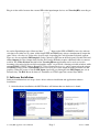
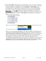
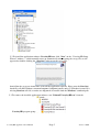
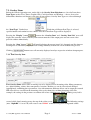
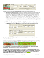
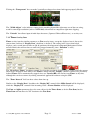
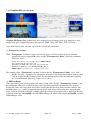
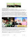
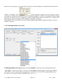
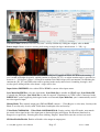
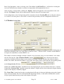
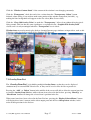
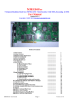
VoverlayHD
PCI-Express Card to Realtime Overlay High-Definition Text and
Graphics on High-Definition Video Input
Application User Manual
Version 1.0.0.0
Copyright © 2014 Inventa Australia Pty Ltd
Table of Contents
1. Main Features & Functions
2. Package Contents
3. Minimum System Requirement
4. Hardware Installation
5. Software Installation
6. Starting the Software
7. Operate VoverlayHD Card
7.1 Generic Operations (Video Preview, Image Grab, Reset etc)
7.2 Overlay Items
7.2.1 Text Overlay Item
7.2.2 Timer Overlay Item
7.2.3 Graphics File Overlay Item
7.2.4 Card Operation Overlay Item
7.2.5 Window Overlay Item
7.3 Overlay Item List (Combine multiple overlay operations)
7.4 Using Multiple VoverlayHD Cards
8. Source Code
VoverlayHD Application User Manual
Page 1
------------------------------------------------------------------------------------------------------------------------------------------------------------------------------------------------------------------------------------------------------------------------------------------------------------------------------------
2
2
2
2
3
6
6
7
9
9
11
12
14
16
17
18
18
Version 1.0.0.0
1. Main Features & Functions:
VoverlayHD is a Realtime High-Definition Text & Graphics on HD Video Overlay PCIe Card with
many features & functions:
On-board ICs instantly mix PC text/graphics/video with live input HD/SD video and output to SDI/HDMI ports
Full 256-Level Alpha blending control on every pixel mixed with incoming video up to 1920X1080-Pixels
Each pixel within video input frame up to 1920X1080 pixels can have different overlay colour & transparency
Full 24-bit overlay colour and 8-bit alpha (ARGB) assignable to and readable from every input video pixel
HD/SD I/O for 720X480/576 ~ 1920X1080-Pixels, 24/25/50/30/60/29.97/59.94/23.97Hz, Interlaced & Progressive
Every output video frame can be grabbed and saved as graphics file and/or raw YUV file
Instant overlay add / delete without visual delay on outputting video signal
Un-limited PC-generated colour text, graphics and video can be overlaid simultaneously on incoming video
Use full Windows GDI/GDI+ power to generate un-limited vector & bitmap graphics overlaid on input video
Up to 16 Multiple cards can be run on the same PC controllable by the same software
Full software control at software level on video Sync, Mixing, Resolution, Progressive/Interlace etc
SDI & HDMI video Input/Output supported and software selectable: 3G-SDI, HD-SDI, SD-SDI, HDMI
Simultaneous SDI and HDMI video output ports outputting same content
Output ports can be software configured to display video only, video plus overlay, overlay only
Internal, External and SDI Signal Sync Modes supported and software selectable
Separate Reference Sync BNC Port available on card back panel
Overlay Content can appear on output ports when no input signal is available
SDI Video Input to Output Pass-through on power loss (PC reboot or powered off)
Input SDI or HDMI Audio is passed onto Output Ports
Live Video Preview on PC Screen in resizable floating window always displaying the output video content
Overlay Text String support different colour, font name, size, background mode, transparency & Unicode
Overlay Graphics Files support for BMP, JPEG, GIF, PNG, TIFF and Targa format
Apply single or a range of “Transparency Colours” on Graphics & Text for Blue-Screen/Chroma-Key effect
Overlay Timer support for time, date, mille-second, frame number
Overlay Card Operation support for screen area clear, alpha change & content rotate, I/O select, etc.
Overlay Windows support for constantly displaying any window’s content to external HD Video Devices
Constant Alpha Channel Value Change under software control for timing and increment
Horizontal and Vertical Moving Text & Graphics Overlay with software configurable steps and times
Instant Overlay Display to external HD Video Devices from multiple overlay items constructed & loaded
Save and Open Overlay Item List Files for repeated use of complicated overlay schemes and patterns
Save & Read eeprom data for card/software identification or other usage: 48 bytes can be read and written.
Full SDK for Software Development inc. full C++, VB, C# source codes of fully functioning executables
SDK & Application run on Microsoft 32-bit/64-bit Windows XP/Vista/7/8 Operating Systems
2. Package Contents:
VoverlayHD PCI-Express Card (1XPCIe)
One Installation CD
One User Manual
One SDK Manual
3. Minimum System Requirement
Hardware: Intel/AMD CPU based PC, one empty 1-Lane (or 4X, 8X, 16X Lane) PCI-Express slot.
Software: Microsoft Windows XP, Vista, Windows 7 or Windows 8, 32-Bit or 64-Bit, DirectX 9 and
above. Please note although running the main VoverlayHD.exe application does not require it, running
the CSharp.exe or VoverlayHDVB.exe application will need the Microsoft .Net Framework 3.5 to be
installed.
4. Hardware Installation
Un-plug the PC’s power cable, open PC case, locate an empty PCI-Express slot, plug in the VoverlayHD
card and screw it firmly to the back-panel.
VoverlayHD Application User Manual
Page 2
Version 1.0.0.0
Plug in video cables between the external HD video input/output devices and VoverlayHD, according to
, Input socket SDI or HDMI is in use by software
the socket Input/Output types illustrated here:
selection to be either one at a time, while Output SDI and HDMI ports always simultaneously output the
same Video + Overlay (or Video only, Overlay only, depending on Card Operation Selection) content.
There are also an optional SDI Output 2 (Same Content as SDI Out on the back panel) Socket JD10 and
a Key Output (Overlay Output Only) Socket JD12 on the PCB that require additional cables to connect
to them. The Video Preview function of the VoverlayHD.exe application can be used to view the
incoming video mixed with overlaid text/graphics on PC screen inside a floating resizable window, while
external HDMI / SDI TV, Bluray Recorders, Video Capture Devices etc. can be connected to the output
SDI/HDMI sockets of the VoverlayHD card to receive its live video output including overlaid text and
graphics. When PC power is lost the SDI Input signal will pass through to the SDI Output port via an
internal relay. The Ref. In can be from a Y luminance or CVBS signal for external Sync Mode.
5. Software Installation
Software installation has two steps: device driver software installation and application software
installation.
5.1 After hardware installation, the MS Windows will inform that new hardware is found:
VoverlayHD Application User Manual
Page 3
Version 1.0.0.0
5.2 Put the VoverlayHD installation CD into PC’s CD/DVD drive, click “Next” button, let Windows
search for device driver specifically from one of the sub-folders (winxp, vista, win7, use win7 subfolder for both Windows 7 and Windows 8) under “driver/32bit” or “driver/64bit” folder
according to the PC’s current Windows version and if Windows is 32-Bit or 64-Bit. During the
driver installation, ignore those warnings claiming the device driver “has not passed Windows
Logo testing…” etc, press “Continue Anyway” to keep going, until the driver is installed, then
Reboot the PC, then (after rebooting) check the Windows’ “ControlPanel” to make sure the
“System->Hardware->DeviceManager ->Sound, video and game controllers” category has a driver
line “VoverlayHD Board” listed for each VoverlayHD card without question or exclamation
mark:
When device driver has been installed properly, Windows will have a pop-up message box at the
lower right corner of the screen:
Please note: after re-installing MS Windows on a PC with VoverlayHD card remaining seated in
PCIe slot, one “Multimedia Controller/PCI Device” or similar line will appear in the Windows’
ControlPannel->System->Hardware->DeviceManager window, preceded by a yellow question
mark or exclamation mark, since Windows will not(cannot) install the device driver software.
This item will need “update driver” operation(right-mouse click then select “Update driver…”) to
install the proper driver software from the “driver” folder on the Setup CD, before the
VoverlayHD card and application software can be used properly. Alternatively, you can delete this
question-mark/exclamation-mark preceded item(right-mouse click them then select “Uninstall”),
highlight the PC’s name in the DeviceManager window then select “Scan for Hardware Changes”,
then follow the same steps as at the start of this section to install the device driver:
VoverlayHD Application User Manual
Page 4
Version 1.0.0.0
5.3 To install the application software VoverlayHD.exe, click “Next” on the “VoverlayHD Setup
Wizard” window --- which normally starts up automatically after inserting the set-up CD, or will
appear after double-clicking the “Start.bat” software on the set-up CD:
,
then follow the on-screen instructions to install the application software. Please note the Start.bat
batch file calls MS Windows command reg.exe: if reg.exe (usually under C:\Windows\system32) is
missing Start.bat will fail, so make sure reg.exe if executable from the Windows’ command path.
5.3 To remove the installed application software, run “Uninstall VoverlayHD.exe” from the
VoverlayHD program group:
VoverlayHD Application User Manual
Page 5
Version 1.0.0.0
6. Starting the Software
After a successful application software installation, a “VoverlayHD.exe” shortcut icon
will
appear on the Windows’ desktop. Mouse double-clicking this icon will start the software. The software
can also be started from Window’s “Start->Program Files->Inventa->VoverlayHD” group.
7. Operate VoverlayHD Card
Once started, VoverlayHD.exe will display its main window:
.
Mouse-clicking the “Action” menu will show its menu items:
Selecting the “Setup Card Overlay” item will start the “Setup VOverlayHD” window, where all the
major operations for VoverlayHD card can be accomplished:
The Setup Window arranges its functions in several main areas: on the top line is the Generic Operation
area, below it on the left is the Overlay Items area, on the right is the Overlay Item List Box, and in
between the Item and Item List Box areas there are Operation Buttons that can be used for Overlay
Items and Item List, such as Display Current Item, Add Item to Item List, Save and Open Item List File,
etc.
VoverlayHD Application User Manual
Page 6
Version 1.0.0.0
7.1 Generic Operations
The upper part of the Setup Window lists several generic operations, inc. overlay card selection (when
multiple VoverlayHD cards are installed), still image grabbing which will display the grabbed video
and/or overlay image in the application’s main window and optionally save them into graphics/YUV files,
live video preview, and Input Test operation.
Checking the
box will start a separate floating and resizable Video Preview Window for the
current VoverlayHD card:
which also has a right-mouse clicking popup menu to operate:
. When mouse
cursor is moving inside Video Preview Window without pressing any mouse button, if Ctrl key is
pressed then the approximate video frame position the current mouse cursor is pointing to will be
automatically undated in the X1/Y1 edit fields of the Location group in the Setup dialog window:
Inside the Video Preview Window, double-clicking left mouse button will toggle between the full-screen
and normal window mode. While at the full-screen mode, pressing the space button also brings the
window back to normal size. When in the normal window mode, pressing down the left mouse button
then moving the mouse will move the window around.
The video displayed inside the preview window is always the same as the video output on the card’s SDI
and HDMI output ports.
The “Full Frame” check box is to select if the previewed video is getting full frame resolution of the
actual video input frame, or ¼ of the actual video frame resolution. Getting full frame resolution (box
checked) will display higher quality preview video on PC screen, in particular the added overlay contents,
but requires much more CPU power and the displayed video is less smooth than using ¼ frame resolution
(“Full Frame” box cleared).
The “Interval” edit box appears only when Windows is not XP: this is the time the application program
pauses between displaying two consecutive video frames: smaller value makes the preview smoother but
consumes more CPU power.
VoverlayHD Application User Manual
Page 7
Version 1.0.0.0
Please note when using multiple VoverlayHD cards on Windows XP, only one card can have live video
preview at any time, trying to preview video while another VoverlayHD card is already previewing
causes a DirectDraw error warning dialog advising to close the other card’s preview first.
Clicking the
button will grab the current video frame into the application’s main window:
,
if the “Save Image to File”/”Save YUV” box at the lower right part of the window is checked when
“Grab Image” button is clicked, a graphics file and/or the grabbed YUV raw data file will be created:
The graphics file will have one of the .bmp, .jpg, .gif(WinXP)/.tif(Non-WinXP), .png file extensions as
typed in the edit field, plus a serial number appended before the ‘.’ character, such as VOverlayHD0.jpg,
VOverlayHD1.bmp etc. The graphics file’s image is the current frame at the currently selected video
input port (SDI or HDMI), with the same video resolution (from 720X480 ~ 1920X1080 pixels) without
any scaling.
The grabbed YUV file is of packed UYVY 4:2:2 format, useful for some YUV play/analysis programs.
The “Deinterlace” check box only shows under Windows XP, checking it will capture de-interlaced
image.
The “Reset Out” button disables then re-enables the SDI and HDMI output ports.
The “Delays” button pops up a window allowing changes to the current card’s line and frame delays:
A “Reset Card” button at the lower-left corner of the Setup Window will close and restart the current
VoverlayHD card, this can be used to rectify any erroneous situation of a card.
VoverlayHD Application User Manual
Page 8
Version 1.0.0.0
7.2. Overlay Items
Below the Generic Operation area, on the left is the Overlay Item Selection area. Overlay Items have
Item Types such as Text, Timer, Graphics File, Card Operation, and Window --- theses are used to
differentiate functions and features each type of item operate. Overlay Item Types are selected through
the “Item Type” Combo box:
. Each time a different Item Type is selected,
specific buttons and combo-box etc controls relevant to that Item Type will be displayed.
Pressing the “Display” button
between the “Overlay Item” and “Overlay Item List” areas will
display the currently selected Overlay Item content onto the video output ports and on-screen video
preview window immediately.
Pressing the “Stop” button
will stop displaying the current item if it is dynamic one like timer or
moving text etc. Previously displayed item’s image normally remains on screen without being erased.
Clicking
button erases all currently displayed overlays on preview window & output ports.
7.2.1 Text Overlay Item
Text Overlay Items allow static or moving text to be displayed over incoming video. Many parameters,
inc. alpha blending, colour, font, transparency, location, duration, etc can be selected and changed.
Appropriately combining these parameters, text with numerous different effects can be output on external
HD video devices overlaid on the incoming video, or by themselves without incoming video. For
example, the settings in the previous screenshot will create a blinking text “Blink” blinking every half a
second, while slowly moving across the top of the video screen:
. The following settings
(note “AlphaBk” is set to 126) will create a word “Blink” with half-transparent background colour:
VoverlayHD Application User Manual
Page 9
Version 1.0.0.0
.
As shown in the screenshot, the Text Overlay Item has two time-changing parameter sets:
(1) Alpha Start & Alpha End Change: Setting these parameters to different values and giving some
values to the Alpha Step, Interval parameters will cause the displayed text to have a changing
visibility every “Interval” time in “Step” increment/decrement, such as gradually fading in or
fading out. The “Alpha Rotate” controls when the changing “Alpha Start” value reaches the
“Alpha End”, if it will gradually change back from the “Alpha End” back to “Alpha Start” in
“Step” increment/decrement, or it will abruptly jump back to the original “Alpha Start” value.
The Alpha “Duration” (below AlphaBk field) controls how long this Alpha Start<->Alpha End
visibility change will last: a zero duration means the changes will last forever until being cancelled
specifically.
(2) X/Y Location Change: Setting the (X1, Y1) and (X2, Y2) values different will cause the text to
move horizontally or vertically, in the increment of “Move Step” value, every “Interval” time,
for “Duration” period (zero Duration means moving forever until being manually stopped):
The “Oneway Move” and “Return Move” check boxes control if the movement will repeat when
reaching the (X2, Y2) position.
As shown in the previous example, the “AlphaBk” value controls the visibility of the text’s surrounding
background colour when the “BkMode” is Opaque and the Transparent CheckBox is cleared:
,
.
The text Font Name, Font Point, Foreground Colour, Background Colour, Background Mode,
Transparency can all be changed by using the corresponding buttons.
Note to create those Transparent Background text as shown above, the “Background Colour” must be
set to Black (RGB = 0,0,0), the BkGr Mode must be “Opaque”, and the “Transparent” checkbox must
be cleared. If the Background Colour is non-black then the resulting text will have a background of
Background Colour such as this (Background Colour is green):
VoverlayHD Application User Manual
Page 10
Version 1.0.0.0
Ticking the “Transparent” box can make 2 partially overlapped text items both appear properly like this:
The “Width Adjust” value indicates empty pixels extending beyond the right-most area of the text string,
useful at some high-resolution (such as 1920X1080) video mode to compensate right-most clipping.
The “Unicode” box allows input of multi-byte characters (Japanese/Chinese/Korean etc.) as overlay text.
7.2.2 Timer Overlay Item
Timer overlay item has similar parameters as Text overlay items, except the displayed text is always the
current time (and date if “Display Date” checkbox is checked). The setting in the screen shot below
displays a one-second interval timer at (20, 0) position with transparent background(Background Colour
must be Black) that will run forever until being stopped manually (since “Duration” is zero):
.
The “Erase Prev. Timer” checkbox controls if to clear the previously displayed timer (if any) when the current
timer item is displayed. Note when a new Timer is defined and the “Display” button is clicked, any previously
defined Timer will be automatically stopped since one VoverlayHD card can have one Timer at any time,
although this can be overcome by writing customized application software using the SDK.
The “Timer Interval” field can have values from 1ms up.
Similar as the “Display Date” checkbox, the “Display MS” controls if the Mille-Second will be displayed,
while the “Display FN” controls if the incoming video’s Frame Number will be displayed.
The Font and Alpha parameters have the same effects for the Timer Items as for the Text Item, but the
Timer Item will not move its X/Y location as the Text Item.
VoverlayHD Application User Manual
Page 11
Version 1.0.0.0
7.2.3 Graphics File Overlay Item
Graphics File Items allow graphics files to be displayed over incoming video or by themselves at the
output video ports. Supported graphics file types are .BMP, .JPG, .GIF, .PNG, .TIF, and .TGA.
Apart from the file name selection, this item has several new parameters:
(1) Transparency Colour
When “Transparent” checkbox is ticked, the overlay process will not display the pixels from the
graphics file whose colour RGB values and the “Transparency Colour” value have minimum
difference, that is:
abs(Rp - Rt) + abs(Gp - Gt) + abs(Bp - Bt) <= TKErrorRange;
where abs(X) is the absolute value of X,
Rp/Gp/Bp is the RGB value of the pixel on the graphics file,
Rt/Gt/Bt is the RGB value of the TransparencyKey Colour,
TKErrorRange is a value >= zero as supplied on the screen.
For example, when “Transparent” checkbox is ticked and the “Transparency Colour” set to “blue”
(RGB= (0,0,255)), a graphics file with people in front of a blue background will be displayed only
with the people over the incoming video, the blue background becomes invisible thus exposing
the video underneath, achieving a “blue-screen” effect.
(2) TKErrorRange
This value makes pixels on the graphics file whose colour values and the “Transparency Colour” value
have minimum difference as indicated above to be invisible(exposing the underneath video content).
Setting this value to be larger than zero will be useful when the area to be made invisible contains nonuniform colour, e.g., a white background contains pixels with colours close to but not exactly the pure
white, as illustrated in the following example where the same overlay graphics file is applied on the same
video but on the left VoverlayHD card with TKErrorRange =0, while on the right VoverlayHD card with
TKErrorRange =220:
VoverlayHD Application User Manual
Page 12
Version 1.0.0.0
(3)Clear Old Overlay Value
This box is only meaningful when box “Transparent” is also ticked:
If Clear Old Overlay Value is ticked, then those pixels in the graphics file whose colour values and the
“Transparency Colour” have the minimum difference (as described in the “Transparency Colour” above)
will become totally transparent, i.e., the video underneath them will be exposed.
If this box is cleared, then those pixels in the graphics file whose colour values and the “Transparency
Colour” have minimum difference as described in the “Transparency Colour” above will combine (logical or)
their old alpha value with the new alpha value on screen, so that if the resulting alpha is nonzero then some
degree of overlay will appear on top of the video – this is useful for example to display an half-transparent
background exposing some of the video underneath. The following are examples using the same graphics file
with red text ABCD in front of a white background, and Transparency Colour is white, Alpha Start / Alpha
End are 128:
(1)Transparent & Clear Old Overlay Value Ticked
(2) Transparent Ticked, Clear Old Overlay Value Cleared
(4) Raster Operation
This controls how the pixels of the graphics file will be combined with the overlay pixels already being
displayed on the same position by previous Overlay operations(if there is any): SRCCOPY means the
new pixels completely replace the original pixel, SRCAND means the new pixels do logical AND with
the original pixels, the BLACKNESS means display black at the positions, etc.
Alpha change, X/Y change, duration, etc parameters have the same meaning as in Text and Timer items.
Graphics File Item has no “AlphaBk” parameter since it has no background colour.
VoverlayHD Application User Manual
Page 13
Version 1.0.0.0
Each time a non-targa(not .tga) graphics file is loaded, its width and height are automatically loaded into the
. When displaying a graphics file item, using these width
“Width” and “Height” fields:
and height, or making these two fields all zeroes, will put the graphics exactly as their original width and height
(in pixels) onto the external TV. If supplying a width or height different from the graphics file’s original width
and height, the displayed graphics will be shrunk or expanded accordingly.
Targa graphics files (.tga) will not have their width and height automatically calculated and they can not be
shrunk or expanded.
7.2.4 Card Operation Overlay Item
Card Operation Overlay Item operates the VoverlayHD card directly, some explanations for these:
“Set Colour”: Once this operation is selected, the “Set Colour” Edit Box appears indicating the ARGB
value in Hex used for setting colour and transparency, and the (X1, Y1) ~(X2, Y2) values will be used as
the video area to be painted with the ARGB overlay value: e.g.,
VoverlayHD Application User Manual
Page 14
Version 1.0.0.0
.
Note Set Colour can be used to erase any area’s overlay contents by setting the A(lpha) value to 0x00.
Rotate Angle: Rotate an area’s overlay pixels using an angle (in degree unit between 1 ~ 359), e.g.:
Rotate Angle operation uses the (X1, Y1) as the rotating area’s upper left corner, the W/H as the rotating
area’s width and height (in pixels), and the rotation is at point (X1, Y1) as origin, rotation angle is specified as
between 1 ~ 359 degrees (values > 359 will be modulus with 360, 0 degree does no rotation). On finishing the
rotation the (X1, Y1) and W/H values will be updated to the newly rotated area’s bounding rectangle. Any
overlay pixels falling off the video frame’s edges will be lost.
Input Socket SDI/HDMI: select either SDI or HDMI as current video input source.
Sync Mode Int/SDI/Ext: select the clock mode, Sync Mode Int is suitable for HDMI input, Sync Mode SDI
is suitable for SDI input, Sync Mode Ext is when an external Y Luminance or CVBS video is connected to the
REF IN BNC socket supplying clock signal to the card. Internal (Sync Mode Int) sync is automatically used if
no video signal is input.
Mixing Mode: This controls output port (SDI and HDMI) content --- Video Bypass is video only, Overlay with
Black is overlay only, Overlay with Video shows both input video and overlay.
Video Mode 720X480 I60… Video Mode 1920X1080 P59.94: Setting various video I/O mode, must match
the actual video signal at the video input port or distorted display will appear. I or P means Interlaced or
Progressive respectively. Selecting these then clicking “Display” button will cause the card to reset itself.
SDI Out Enable/Disable: Enable or Disable video output at output ports.
VoverlayHD Application User Manual
Page 15
Version 1.0.0.0
Some Card Operations, such as selecting a new Video Mode (1920X1080I50 etc.), will involve resetting the
card so if Video Preview window is on those card operations will automatically close it.
After selecting a card operation, clicking the “Display” button will apply the selected operation to the card,
also the “Test Input” button will be automatically clicked to show the new input status.
Card configuration set by Card Operation will be remembered by the VoverlayHD card so when the software
is re-started, even after power is lost or PC is restarted, the previously selected configuration will be used.
7.2.5 Window Overlay Item
Window Overlay Item allows any window on the Windows’ desktop to be displayed at video output ports, in
front of the incoming video or by itself. This is useful to create a “Video in Video” result on external HD TV,
or display live animation to external HD TV, etc.
The window selection is through a window’s handle, or its class name, title, or its root window’s class name
and title. Pressing the “Get A Window Handle” button
once, then move the mouse
cursor(now changed to I-Beam shape) to any window and single click that window, that clicked window’s
handle, class name, title and root window’s class name, title values will be copied into the corresponding fields
.
on the Setup Overlay Window:
Clicking the “Client Area Only” checkbox means only displaying the selected window client area’s contents.
Clicking the “Erase on Exit” checkbox means the window’s display will be cleared when the display duration
expires or the display is manually stopped.
The “Pause Time” means how long the executing thread will pause in between displaying consecutive frames
of the selected window. For a live video/animation displaying window, set this time to 40~80 mille-seconds
will give good smooth moving result on the output video ports.
VoverlayHD Application User Manual
Page 16
Version 1.0.0.0
Click the “Window Content Static” if the content of the window is not changing constantly.
Click the “Transparent” check box and select a colour from the “Transparency Colour” button
initiated colour dialog, if you wish to make some portion of the window transparent (invisible), e.g.
making the blue background to disappear on the live video (Blue Screen effect).
Click the “Clear Old Overlay Value” to make the “Transparency” effect clean without shivering pixels
flying around. This box has the same significance as explained in the “Graphics File Overlay Item”
section, and it is only meaningful when the “Transparent” box is ticked.
Window item can overlay movie-play-back or dynamic Internet page windows on input video, such as this
VideoLan video play-back overlaid on live Simpson TV Program:
7.3 Overlay Item List
The “Overlay Item List” is for holding multiple Overlay Items, so that they can be displayed
simultaneously on external HD Video device, or they can be saved as files for later repeated use.
Pressing the “Add”, or “Delete” button in the middle of the screen will add or delete the current item into
or from the Overlay Item List box, while with one item selected in the list box, pressing “MoveUp” or
“MoveDown” button will change the selected item’s position in the list.
When some items have been selected in the Item List box, pressing the “Display Selected Items” button
will display these items’ contents on the video output ports and the live video preview window, in the
order of their positions in the list box:
VoverlayHD Application User Manual
Page 17
Version 1.0.0.0
Pressing the “Stop” button will stop the displaying.
The “Save” and “Open” buttons are used to save all items inside the Item List Box to file, and to load a file’s
contents back into the Item List Box (when loading from an item list file, items already in the list box will be
cleared), respectively.
7.4 Using Multiple VoverlayHD Cards
To operate multiple (2~16) VoverlayHD cards on the same PC, select each card’s number from the
“Selected Card:” Combo box (first card is number 0), then apply any operation on this card.
When using timer-based overlay items such as Timer or moving text, manual start of an item will
automatically stop other timer-based items previously defined even on another VoverlayHD card. For
example, whenever a “Timer” Overlay Item is started on the currently selected card, the previously
applied Timer item on another VoverlayHD card will be automatically stopped. To make multiple cards
all displaying their own Timer Overlay Items simultaneously, the Overlay Item List needs to be used:
define a Timer for each individual VoverlayHD card then click the “Add” button to add this Timer into
the Overlay Item List ---- when all timers for all cards are added to the Overlay Item List, click the
“Select All” button below the Overlay Item List ListBox, then click “Display Selected Items” button
next to it, all VoverlayHD cards with Timer defined will start displaying overlaid timers simultaneously.
8. Source Code
The VoverlayHD.exe software is supplied with full C++ source code together with the VoverlayHD
card’s SDK. A sample VisualBasic application VoverlayHDVB.exe and a sample C# application
CSharp.exe are also supplied with full source codes: all source codes and their VisualStudio 2008 Pro
project files are under the “src” folder of the Setup CD: note MS .net framework 3.5 is needed to run the
VB and C# programs.
VoverlayHD Application User Manual
Page 18
Version 1.0.0.0