1
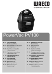
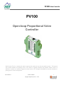
PV100 Valve Controller PV100 Open-loop Proportional Valve Controller High Country Tek, Inc. reserves the right to improve this product at any time and without notice. This manual may contain mistakes and printing errors. The content is regularly checked and updated. Please check our website or contact our customer support for latest version. HCT accepts NO liability for technical mistakes or printing errors or their consequence. 021-PV100 Rev A PV100 User Manual Copyright © High Country Tek, Inc. – 2013 1 PV100 Valve Controller Contents Welcome ................................................................................................................................................................... 3 Product Application Guidelines ................................................................................................................................. 4 PV100 Controller ....................................................................................................................................................... 5 Operating Specifications ................................................................................................................................... 5 Physical Description.......................................................................................................................................... 6 User Interface ................................................................................................................................................... 6 Configuration ..................................................................................................................................................... 7 Parameter List ................................................................................................................................................. 10 Modes of Operation ........................................................................................................................................ 13 Wiring .............................................................................................................................................................. 24 Order Information .................................................................................................................................................... 25 Application Examples .............................................................................................................................................. 26 Single Solenoid Control .................................................................................................................................. 26 Dual Solenoid Control ..................................................................................................................................... 27 021-PV100 Rev A PV100 User Manual Copyright © High Country Tek, Inc. – 2013 2 PV100 Valve Controller Welcome Welcome to High Country Tek Inc. HCT is North America’s foremost independent designer and producer of modular, ruggedized digital and analog electronic controllers for the fluid power industry. From our factory in California, we manufacture ‘specialty’ controllers for specific functions and the user programmable ‘DVC family’ to enable large area networked system solutions. The modules are used in mobile, industrial and marine applications. They are also applied successfully in other industry segments. HCT products are encapsulated in solid flame resistant material for maximum durability, electrical integrity and complete environmental security. HCT is a market leader in many application arenas, including hydraulic generator, e-Fan and hydraulic fan system controls. These controllers facilitate significant fuel, emission and operational savings. HCT’s market neutrality offers integration with any hydraulic OEM valves, pumps, sub-systems or systems. For more information, please visit us at: www.hctcontrols.com. Cautions Changing setup values or operating modes while a machine is running may cause unintended machine movement. It could lead to possible injury or death. Any moving parts should be disabled prior to changing setup values or operating modes. In every case, exercise caution and work should be completed only by qualified personnel. 021-PV100 Rev A PV100 User Manual Copyright © High Country Tek, Inc. – 2013 3 PV100 Valve Controller Product Application Guidelines ALWAYS do the following FULLY read this manual and accompanying data sheets BEFORE starting. Isolate this unit from all other equipment BEFORE any form of welding. Isolate the controller from ANY form of battery charging or battery boosting. Be aware of the electrical & mechanical connections, and the expected reactions of the equipment. Operate the units within the temperature range. Use the correct tools to do the job (i.e. P.C., software) etc. Separate High Voltage AC cables from Low Voltage DC signal and supply cables. Make sure power supply is CORRECT, ELECTRICALLY CLEAN, STABLE, and rated for the full load. Make sure the controller output voltage & current is compatible with the equipment. All unused wires / terminals should be terminated safely. Ensure ALL connectors have no unintended SHORT or OPEN circuits. Ensure ALL connectors are wired correctly, secure, locked in place and fully connected. Disconnect or connect wires to or from this unit only when the power supply is disconnected. Use adequate screening in areas of intense Radio Frequency fields. Ensure ALL work areas are clear of personnel before operating the controller. Follow and abide by local and country health & safety standards. 021-PV100 Rev A PV100 User Manual Copyright © High Country Tek, Inc. – 2013 4 PV100 Valve Controller PV100 Controller The ProValve100 controller drives proportional solenoid valves. The output current is proportional to the command input. Once configured, the settings are permanently stored in the controller memory. PV100 Features Easily configured using HCT Graphical User Interface (GUI) or HCT Hand Held Interface (HHI) LED indication of power, output current and fault status DIN-rail mount housing with removable terminal blocks Multiple modes for single and dual coil applications, programmable enable input All input and output limits are independently adjustable Adjustable output with short circuit protection Operating Specifications Supply Voltage 12 to 30VDC Supply Current Valve current + 50mA (Quiescent Max) Output Current Standard: 2.5A max -L: 500mA MAX -N: 250mA MAX Coil Resistance Standard: 2Ω MIN -L: 10Ω MIN –N: 10Ω MIN Reference Voltages -10V, +10V @ 2mA Dither Frequency 35, 41, 49, 61, 81, 122, 244Hz (Select OFF for PWM frequency 15.63KHz) Two-speed Ramp Time 0.10 to 16.96 seconds Analog Slew Time 0.1 to 30.0 seconds Analog Input Range [0, 10]V, [-10, +10]V, [0, 5]V, [5, +5]V, [0, 20]mA Analog Input Impedance > 100K for voltage input 500 for current input. Digital Input Range -24: 12 to 30VDC -115: 100 to 130VAC -230: 210 to 250VAC Digital Input Impedance -24: 3.3k -115: 33k -230: 75 Operating Temperature Range 0º to 70º C (operating); -40º to 85º C (storage) Enclosure Compact Dimensions Inch: 3.9 L x 4.5 W x 0.4 H, Mm: 99 L x 114.5 W x 10 H 021-PV100 Rev A PV100 User Manual Copyright © High Country Tek, Inc. – 2013 5 PV100 Valve Controller Physical Description The boxed numbers 1 to 16 represent the terminal positions. A label on the side of the module provides a list of terminal functions. There are four indicator LEDs. The “POWER” LED is green when the applied voltage is within the operating range. The “OUTPUT A” and “OUTPUT B” LED’s are yellow and the brightness will vary with the output current. In the case of a fault, the “FAULT” LED will display solid red until clearing faults by moving the command signal out of the active range or cycling the power. See Fault Status for details. The PV100 communicates with the Graphical User Interface through the RJ-11 to DB9 convertor. It must be powered when configuring the settings. User Interface The PV100 has a number of internal settings. Users can open the Graphical User Interface to view, make changes and save the settings in a data file which can be uploaded to any PV100 controller. The Hand Held Interface can also be used to view and make changes, but this device does not have the capability to save the settings in a data file. The programmer, cable and adapter are self-contained which makes the HHI a viable alternative for field work. The following diagram shows the RJ-11 to DB9 converter pin-out: 021-PV100 Rev A PV100 User Manual Copyright © High Country Tek, Inc. – 2013 6 PV100 Valve Controller Configuration The GUI has 4 buttons (ran from a PC): Lock, Unlock, Up, and Down. There are short-cut keys: ‘/’(lock), ‘*’(unlock), ‘+’(up), and ‘-‘(down). The HCT Hand Held Interface has the same 4 buttons and 2-line LCD. Use the up and down arrows to navigate through the parameter list. The display will show the next parameter in the list when pressed. The parameter name is on the first line and the value is on the second line. The list is in circular, stepping down from the last parameter to the first and vice-versa. There are three types of parameters: fixed; monitor; and variable. Fixed parameters show the module’s firmware version, etc. Monitor parameters display output current and system voltage. Use variable parameters to configure the controller, such as maximum output current, operating mode, etc. Some parameters combine variable and monitor in one line. Use it to set a variable according to the current monitor value. Press the unlock button to enter the edit mode. An asterisk (*) will appear at the beginning of the second line. Use the up and down buttons to change the value. For parameters containing both variable and monitor, the monitor data is in square brackets. Press the lock button to save the parameters and end edit mode. When the lock button is pressed, the changes take effect immediately. Change values only when the machine is NOT running. 021-PV100 Rev A PV100 User Manual Copyright © High Country Tek, Inc. – 2013 7 PV100 Valve Controller “Read settings from controller” displays a static table of values from non-volatile memory. The changes made to the settings by selecting “lock” are not updated in the table unless “read settings from controller” is selected again. To save the settings into a file for future use, click “read settings from controller” before clicking “save settings to file”. 021-PV100 Rev A PV100 User Manual Copyright © High Country Tek, Inc. – 2013 8 PV100 Valve Controller When uploading settings from a data file, the static table shows the settings from the data file, but they are not in the controller yet. Click “write settings to controller” before clicking “read settings from controller”. After this step, the static table will display the PV100 settings from the data file. 021-PV100 Rev A PV100 User Manual Copyright © High Country Tek, Inc. – 2013 9 PV100 Valve Controller Parameter List The following table outlines the PV100 parameters as well as the limits and units of measure for each parameter. Parameter Limits Units PV100 Version # Mode A1, D1, D2, D3 0 to 7 Mode # A Minimum input -100 to 100 % A Maximum input -100 to 100 A Minimum output A Low/Over output % * A * A * 0.01 to 2.50 0.01 to 2.50 A Maximum output 0.01 to 2.50 A B Minimum input -100 to 100 % B Maximum input -100 to 100 % B Minimum output 0.01 to 2.50 B Low/Over output * A * A * 0.01 to 2.50 B Maximum output 0.01 to 2.50 A Dither frequency 35, 41, 49, 61, 81, 122, 244 Hz (select OFF for PWM frequency 15.63KHz) Input slew time 0.0 to 30.0 Seconds Ramp up low 0.10 to 16.96 Seconds Ramp up high 0.10 to 16.96 Seconds Ramp down high 0.10 to 16.96 Seconds Ramp down low 0.10 to 16.96 Seconds Output current A Supply voltage Volts Fault status Fault * 0 to 500mA for –L version, 0 to 250mA for –N version 021-PV100 Rev A PV100 User Manual Copyright © High Country Tek, Inc. – 2013 10 PV100 Valve Controller PV100 - The title parameter is fixed. It displays the model number and the firmware version. MODE AI D1 D2 D3 - 8 modes of operation. AI is the analog input, D1, D2, and D3 are digital inputs. See Modes of Operation for details. A MINIMUM INPUT - Sets the minimum command input for coil A (0 to 100%). The value in the brackets is the present command input. A MAXIMUM INPUT - Sets the maximum command input for coil A (0 to 100%). The output will hold its max value when the input is greater than this value. The value in the brackets is the present command input. A MINIMUM OUTPUT - Sets the minimum output current for coil A (Amps). The value in the brackets is the present output current. A LOW/OVR OUTPUT - Sets coil A current output when low speed is chosen in digital input mode. It also sets the current output for the forward override command in analog modes (Amps). A MAXIMUM OUTPUT - Sets the maximum output current for coil A (Amps). The value in the brackets is the present output current. B MINIMUM INPUT - Sets the minimum command input for coil B (0 to -100%). The value in the brackets is the present command input. B MAXIMUM INPUT - Sets the maximum command input for coil B (0 to -100%). The output will hold its max value when the input is greater than this value. The value in the brackets is the present command input. B MINIMUM OUTPUT - Sets the minimum output current for coil B (Amps). The value in the brackets is the present output current. B LOW/OVR OUTPUT - Sets coil B current output when low speed is chosen in digital input mode. It also sets the current output for the reverse override command in analog modes (Amps). B MAXIMUM OUTPUT - Sets the maximum output current for coil B (Amps). The value in the brackets is the present output current. DITHER FREQ. - Set the PWM or dither frequency according to the valve specifications. This parameter is variable. Options: 35, 41, 49, 61, 81, 122, 244, (Select OFF for 1000Hz) INPUT SLEW TIME - Sets the rate of change of the command input for full range ramping up and down. RAMP UP LOW - Sets the time to ramp the output from off to low speed. This parameter applies only to two-speed modes. The Ramp Up Low parameter is variable. 021-PV100 Rev A PV100 User Manual Copyright © High Country Tek, Inc. – 2013 11 PV100 Valve Controller RAMP UP HIGH - Sets the time to ramp the output from low speed to high speed. This parameter applies only to two-speed modes. The Ramp Up High parameter is variable. RAMP DOWN HIGH - Sets the time to ramp the output from high speed to low speed. This parameter applies only to two-speed modes. The Ramp Down High parameter is variable. RAMP DOWN LOW - Sets the time to ramp the output from low speed to off. This parameter applies only to twospeed modes. The Ramp Down Low parameter is variable. OUTPUT CURRENT - Displays the present output current. This parameter is a monitor type. SUPPLY VOLTAGE - Displays the module’s power supply voltage. It is helpful for troubleshooting. This parameter is a monitor type. FAULT STATUS - The Fault LED displays solid red for faults: Open Output, Voltage Drop and Low –10V Supply. 021-PV100 Rev A PV100 User Manual Copyright © High Country Tek, Inc. – 2013 12 PV100 Valve Controller Modes of Operation The PV100 has 8 modes of operation. Mode AIN DIN1 DIN2 DIN3 0 SD -- OF OR Speed/Direction Not Used Forward Override Reverse Override 1 DR -- -- HS Direction Not Used Not Used High Speed 2 SP FW RV -- Speed Forward Enable Reverse Enable Not Used 3 -- FW RV HS Not Used Forward Enable Reverse Enable High Speed 4 SD EN OF OR Speed/Direction Enable Forward Override Reverse Override 5 DR EN -- HS Direction Enable Not Used High Speed 6 SP EN RV -- Speed Enable Reverse Not Used 7 -- EN RV HS Not Used Enable Reverse High Speed Mode 0 - Both speed and direction are controlled by the analog input. 0 to 100% input controls coil A current proportionally. 0 to -100% input controls coil B current proportionally. DIN2 enables forward override; current output is the override setting for coil A. DIN3 enable reverse override; current output is the override setting for coil B. Forward override supersedes reverse override. Mode 1 - 0 to 100% input enables coil A output. 0 to -100% input enables coil B output. When the high speed input (DIN3) is off, the speed is set to the minimum output value. When the high speed input (DIN3) is on, the speed is set to the maximum output value. Mode 2 - The speed is controlled proportionally by the analog input of 0 to 100% only. DIN1 enables coil A in forward direction. DIN2 enables coil B in reverse direction. Reverse override supersedes forward override. 021-PV100 Rev A PV100 User Manual Copyright © High Country Tek, Inc. – 2013 13 PV100 Valve Controller Mode 3 - AIN is not used. DIN1 enables forward direction. DIN2 enables reverse direction. When DIN3 is off, the speed is set to the low speed output value. When DIN3 is on, the speed is set to the maximum output value. Reverse override supersedes forward override. Mode 4 - Exactly the same function as Mode 0, except the enable input (DIN1) enables the module. 0 to 100% input controls coil A current promotionally. 0 to -100% input controls coil B current proportionally. Digital inputs provide forward and reverse overrides. Forward override supersedes reverse override. Mode 5 - Exactly the same function as Mode 1, except the enable input (DIN1) enables the module. 0 to 100% input enables coil A output. 0 to -100% input enables coil B output. When the high speed input (DIN3) is off, the speed is set to the minimum output value. When the high speed input (DIN3) is on, the speed is set to the maximum output value. Mode 6 - Exactly the same function as Mode 2, except the enable input (DIN1) enables the module. By default, it enables coil A in forward direction. The speed is controlled proportionally by the analog input of 0 to 100% only. DIN2 enables coil B in reverse direction. Reverse override supersedes forward override. Mode 7 - Exactly the same function as Mode 3, except the enable input (DIN1) enables the module. DIN2 enables reverse direction. When DIN3 is off, the speed is set to the low speed output value. When DIN3 is on, the speed is set to the maximum output value. Reverse override supersedes forward override. 021-PV100 Rev A PV100 User Manual Copyright © High Country Tek, Inc. – 2013 14 PV100 Valve Controller Mode 0 and Mode 4: dual-coil proportional control with forward and reverse overrides. -21% input commands coil B current to 0.29A. 021-PV100 Rev A -39% input commands coil B current to 0.43A. PV100 User Manual Copyright © High Country Tek, Inc. – 2013 -84% input commands coil B current to 0.82A. 15 PV100 Valve Controller Mode 0 and Mode 4: dual-coil proportional control with forward and reverse overrides. Switch the “reverse override” ON, coil B gets the override current setting 0.3A. Switch “forward override” ON while the “reverse override” is still ON, coil A gets the override current setting 0.3A. Switch both overrides OFF, the PV100 resumes normal operation. -84% input commands coil B to 0.82A. The Forward override has a higher priority than the reverse override. 021-PV100 Rev A PV100 User Manual Copyright © High Country Tek, Inc. – 2013 16 PV100 Valve Controller Mode 0 and Mode 4: dual-coil proportional control with forward and reverse overrides. -1.6% input commands 0 current to both coils. This is within the deadband. 021-PV100 Rev A 28% input commands coil A current to 0.34A. PV100 User Manual Copyright © High Country Tek, Inc. – 2013 53% input commands coil A current to 0.55A. 17 PV100 Valve Controller Mode 1 and Mode 5: dual coil 2 speed control. -98% input enables coil B current. High Speed switch (DIN3) is off, the output is 0.3A (B low/ovr output). 021-PV100 Rev A -52% input enables coil B current. High Speed switch (DIN3) is off, the output is 0.3A (B low/ovr output). PV100 User Manual Copyright © High Country Tek, Inc. – 2013 -52% input enables coil B current. High Speed switch (DIN3) is ON, the output is 0.94A (B Max Output). 18 PV100 Valve Controller Mode 1 and Mode 5: dual coil 2-speed control. -2.4% input commands 0 current to both coils. This is within the deadband. 021-PV100 Rev A 56% input enables coil A current. High Speed switch (DIN3) is off, the output is 0.3A (A low/ovr output). PV100 User Manual Copyright © High Country Tek, Inc. – 2013 56% input enables coil A current. High Speed switch (DIN3) is ON, the output is 0.94A (A Max Output). 19 PV100 Valve Controller Mode 2 and Mode 6: dual-coil proportional control with forward and reverse enable switches. Only the positive input is valid. -50% commands both coils 0A. 021-PV100 Rev A 28.8% positive input commands both coils to 0A because DIN1 and DIN2 are OFF. PV100 User Manual Copyright © High Country Tek, Inc. – 2013 28.8% input commands coil A to 0.35A when DIN1 is ON. 20 PV100 Valve Controller Mode 2 and Mode 6: dual-coil proportional control with forward and reverse enable switches. 56% input commands coil A to 0.58A when DIN1 is ON. 021-PV100 Rev A 56% input commands coil B to 0.58A when DIN2 is ON and DIN1 is OFF. PV100 User Manual Copyright © High Country Tek, Inc. – 2013 Coil B (DIN2) has a higher priority than coil A (DIN1). 21 PV100 Valve Controller Mode 3 and Mode 7: dual coil 2-speed control. DIN1 enables coil A, DIN2 enables coil B, DIN3 enables high speed. AIN -96% commands both coils to 0A because Digital inputs are all OFF. 021-PV100 Rev A DIN1 is ON, DIN2 is OFF, DIN3 is OFF, coil A is set to the Low/ovr current setting of 0.3A. PV100 User Manual Copyright © High Country Tek, Inc. – 2013 DIN1 is ON, DIN2 is OFF, and DIN3 is ON. Coil A is set to the maximum current setting of 0.95A. 22 PV100 Valve Controller Mode 3 and Mode 7: dual coil 2-speed control. DIN1 enables coil A, DIN2 enables output B, DIN3 enables high speed. DIN1 is ON, DIN2 is ON, DIN3 is OFF, coil B is set to the Low/ovr current setting of 0.3A. DIN1 is ON, DIN2 is ON, DIN3 is ON, coil B is set to the maximum current setting of 0.95A. Coil B (DIN2) has a higher priority than coil A (DIN1). Coil B (DIN2) has a higher priority than coil A (DIN1). 021-PV100 Rev A PV100 User Manual Copyright © High Country Tek, Inc. – 2013 DIN1 is OFF, DIN2 is ON, DIN3 is OFF, coil B is set to the Low/ovr current setting of 0.3A. 23 PV100 Valve Controller Wiring Terminal connections are listed in the table below. Terminal Name Function 1 +V Supply +24V 2 Supply Common COM 3 +10V Reference +10V OUT 4 -10V Reference -10V OUT 5 Signal Input + IN+ 6 Signal Voltage Input - INV- 7 Frame Ground GND 8 Signal Current Input - INI- 9 Output A OUT A 10 Supply Common COM 11 Output B OUT B 12 Supply Common COM 13 Digital Input Common DCOM 14 Digital Input #1 DIN1 15 Digital Input #2 DIN2 16 Digital Input #3 DIN3 021-PV100 Rev A PV100 User Manual Copyright © High Country Tek, Inc. – 2013 24 PV100 Valve Controller Order Information The following is a break-down of the PV100 part numbering system: PV100-XX-X Blank = 2.5A max output -L = 500mA max output -N = 250mA max output 24 = 24VDC digital inputs 115 = 115VAC digital inputs 230 = 230VAC digital inputs Required Communication Cables: For the Hand Held Interface Device: P/N: PCA-1 For the PC software SAM: PN: PCA-1 and P/N: 108-00119 P/N: PCA-1 021-PV100 Rev A P/N: 108-001119 PV100 User Manual Copyright © High Country Tek, Inc. – 2013 25 PV100 Valve Controller Application Examples Single Solenoid Control +V Power Input 12 - 30VDC FUSE PWR 1 DIN 1 DIN 1 14 DIN 2 DIN 2 15 DIN 3 DIN 3 16 Ref. Out 3 +10VDC @ 2mA 4-20mA mA I/P 0-5VDC 0-10VDC VDC I/P AN I/P 5 VDC I/P 0-5VDC 0-10VDC Ref. Out 4 Frame GND 7 Sig Current GND 8 Connect for mA IP Sig Vol GND 6 PWR GND 2 Dig I/P GND 13 PV100 Electronic Valve Controller Coil A 9 Coil A 10 Coil B 12 Prop. PWM (Sourcing) Prop. PWM (Sourcing) Coil B 11 021-PV100 Rev A PV100 User Manual Copyright © High Country Tek, Inc. – 2013 26 PV100 Valve Controller Dual Solenoid Control +V Power Input 12 - 30VDC FUSE PWR 1 DIN 1 DIN 1 14 DIN 2 DIN 2 15 DIN 3 DIN 3 16 Ref. Out 3 +10VDC @ 2mA 4-20mA mA I/P 0-5VDC 0-10VDC VDC I/P AN I/P 5 VDC I/P 0-5VDC 0-10VDC Ref. Out 4 -10VDC @ 2mA Frame GND 7 Sig Current GND 8 Connect for mA IP Sig Vol GND 6 PWR GND 2 Dig I/P GND 13 PV100 Electronic Valve Controller Coil A 9 Coil A 10 Coil B 12 Coil B 11 021-PV100 Rev A Prop. PWM (Sourcing) Prop. PWM (Sourcing) PV100 User Manual Copyright © High Country Tek, Inc. – 2013 27 PV100 Valve Controller - - For a full list of authori ed distributors worldwide, please visit: For customer service, pricing, order placement and application support, contact us through E-mail at: A SUN Hydraulics C ompany 20 old Flat Court Nevada City, CA, Tel: (1) 0 2 2 Fa :(1) 0 2 2