1
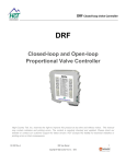
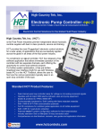
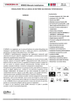
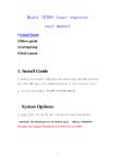
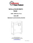
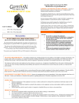
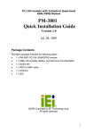
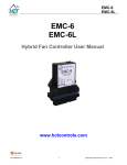
MVP-F MVP-F Closed-loop Proportional Valve Controller User Manual www.hctcontrols.com 021-MVP-F Rev B 1 Copyright © High Country Tek, Inc. – 2014 MVP-F Revision Record Rev Rev A Rev B Description Initial Revision Upgrade to 32V and IP65 ratings 021-MVP-F Rev B Date ReleasedLast Updated by 5-Feb-14 WB 14-Oct-14 WB 2 Copyright © High Country Tek, Inc. – 2014 MVP-F Contents Revision Record ...................................................................................................................................................... 2 HCT Introduction ..................................................................................................................................................... 4 Product Use Limitations .......................................................................................................................................... 4 Product Application Guidelines ............................................................................................................................... 5 MVP-F Controller .................................................................................................................................................... 6 Operating Specifications ................................................................................................................................. 6 Physical Description........................................................................................................................................ 7 User Interface ................................................................................................................................................. 7 Configuration ................................................................................................................................................... 8 Parameter List ............................................................................................................................................... 11 PID Algorithm ................................................................................................................................................ 14 Setup Procedure ........................................................................................................................................... 14 Wiring ............................................................................................................................................................ 16 Order Information .................................................................................................................................................. 16 Application Examples ............................................................................................................................................ 17 Single Solenoid Control ................................................................................................................................ 17 021-MVP-F Rev B 3 Copyright © High Country Tek, Inc. – 2014 MVP-F HCT Introduction Welcome to High Country Tek Inc. HCT is North America’s foremost independent designer and producer of modular, ruggedized digital and analog electronic controllers for the fluid power industry. From our factory in California, we manufacture ‘specialty’ controllers for specific functions and the user programmable ‘DVC family’ to enable large area networked system solutions. The modules are used in mobile, industrial and marine applications. They are also applied successfully in other industry segments. HCT products are encapsulated in solid flame resistant material for maximum durability, electrical integrity and complete environmental security. HCT is a market leader in many application arenas, including hydraulic generator, e-Fan and hydraulic fan system controls. These controllers facilitate significant fuel, emission and operational savings. HCT’s market neutrality offers integration with any hydraulic OEM valves, pumps, sub-systems or systems. For more information, please visit us at: www.hctcontrols.com. Product Use Limitations HCT products may not be suited for any of the following applications: Any product which comes under the Federal Highway Safety Act, namely steering or braking systems for passenger-carrying vehicles or on-highway trucks. Aircraft or space vehicles. Ordinance or military equipment. Life support equipment. Any end product which, when sold, comes under U.S. Nuclear Regulatory Commission rules and regulations. HCT does not have any performance assurance programs for testing their products for the above applications. HCT's products are not designed for these applications and HCT does not warrant, recommend, or specifically approve its products for these applications. The user shall be solely responsible for any loss or damages occasioned by breach of the provisions of this paragraph and shall carry product liability and liability insurance to insure against such loss or damages. 021-MVP-F Rev B 4 Copyright © High Country Tek, Inc. – 2014 MVP-F Cautions Changing setup values or operating modes while a machine is running may cause unintended machine movement. It could lead to possible injury or death. Any moving parts should be disabled prior to changing setup values or operating modes. In every case, exercise caution and work should be completed only by qualified personnel. Product Application Guidelines ALWAYS do the following FULLY read this manual and accompanying data sheets BEFORE starting. Isolate this unit from all other equipment BEFORE any form of welding. Isolate the controller from ANY form of battery charging or battery boosting. Be aware of the electrical & mechanical connections, and the expected reactions of the equipment. Operate the units within the temperature range. Use the correct tools to do the job (i.e. P.C., software) etc. Separate High Voltage AC cables from Low Voltage DC signal and supply cables. Make sure power supply is CORRECT, ELECTRICALLY CLEAN, STABLE, and rated for the full load. Make sure the controller output voltage & current is compatible with the equipment. All unused wires / terminals should be terminated safely. Ensure ALL connectors have no unintended SHORT or OPEN circuits. Ensure ALL connectors are wired correctly, secure, locked in place and fully connected. Disconnect or connect wires to or from this unit only when the power supply is disconnected. Use adequate screening in areas of intense Radio Frequency fields. Ensure ALL work areas are clear of personnel before operating the controller. Follow and abide by local and country health & safety standards. 021-MVP-F Rev B 5 Copyright © High Country Tek, Inc. – 2014 MVP-F MVP-F Controller The MVP-F controller drives proportional solenoid valves in a closed loop system to follow a command signal. When the feedback is greater than the command input, the coil receives full current; when the feedback is less than the command input, the coil receives no current. Once configured, the settings are permanently stored in the controller memory. MVP-F Features Easily configured using HCT Graphical User Interface (GUI) or HCT Hand Held Interface (HHI) LED indicators for power, output current and fault status Permanently sealed, standard DIN 43650 Form A connector body with pre-wired 18AWG PVC cable Multiple modes for open loop, closed loop and inverted Single coil applications, feedback input only for closed-loop applications All input and output limits are independently adjustable Adjustable output with short circuit protection, fully adjustable PID control loop User configurable over and under limit handling Operating Specifications Supply Voltage 9 to 32VDC Supply Current Valve current + 20mA (Quiescent Max) Output Current -06A: 600mA MAX Coil Resistance 2Ω MIN. Reference Voltages +5V @ 2mA Dither Frequency 30, 50, 75, 100, 125, 150, 175, 200, 225, 250, 275, 300, 1000Hz Analog Input Range -F1V: 0 to 10V -F2A: 4 to 20mA Analog Input Impedance -F1V: 12K -F2A: 250 Operating Temperature Range -40º to 85º C (operating); -60º to 90º C (storage) Enclosure 33% glass reinforced, heat stabilized, black polyamide 66 Dimensions Inch: 2.4 L x 1.2 W x 0.75 H; Mm: 60 L x 30 W x 19 H NEMA/IP Rating NEMA 4 / IP67 021-MVP-F Rev B 6 -12A: 1.2A MAX -25A: 2.5A MAX Copyright © High Country Tek, Inc. – 2014 MVP-F Physical Description 60mm 30mm 19mm + DIN 43650 Form A There are two indicator LEDs: STATUS and OUTPUT. The STATUS LED is green when the applied voltage is within the operating range. The OUTPUT LED is yellow and the brightness will vary with the output current. In the case of a fault the STATUS LED will flash red with a flash code. See Fault Status for details. The MVP communicates with the Graphical User Interface through an infrared interface port to RS232. The infrared adapter clips onto the MVP-F aligning with the notches in the sides. It must be powered when configuring the settings. User Interface The MVP has a number of internal settings. Users can open the Graphical User Interface to view, make changes and save the settings in a data file, which can be uploaded to any MVP controller. The users can use the Hand Held Interface to view and make changes, but can not save the settings in a data file. The programmer, cable and adapter are self-contained which makes HHI a viable alternative for field work. 021-MVP-F Rev B 7 Copyright © High Country Tek, Inc. – 2014 MVP-F Configuration The GUI has 4 buttons: Lock, Unlock, Up, and Down. There are short-cut keys: ‘/’(lock), ‘*’(unlock), ‘+’(up), and ‘‘(down). The HCT Hand Held Interface has the same 4 buttons and a 2-line LCD display Use the up and down arrows to navigate through the parameter list. The display will show the next parameter in the list when pressed. The parameter name is on the first line and the value is on the second line. The list scrolls, stepping down from the last parameter to the first and vice-versa. There are three types of parameters: fixed; monitor; and variable. Fixed parameters show the module’s firmware version, etc. Monitor parameters display output current and system voltage. Use variable parameters to configure the controller, such as maximum output current, operating mode, etc. Some parameters combine variable and monitor in one line. Use it to set a variable according to the current monitor value. Press the unlock button to enter the edit mode. An asterisk (*) will appear at the beginning of the second line. Use the up and down buttons to change the value. For parameters containing both variable and monitor, the monitor data is in square brackets. Press the lock button to save the parameters and end edit mode. When the lock button is pressed, the changes take effect immediately. Change values only when the machine is NOT running. 021-MVP-F Rev B 8 Copyright © High Country Tek, Inc. – 2014 MVP-F “Read settings from controller” displays a static table of values from non-volatile memory. The changes made to the settings by selecting “lock” are not updated in the table unless “read settings from controller” is selected again. To save the settings into a file for future use, click “read settings from controller” before clicking “save settings to file”. 021-MVP-F Rev B 9 Copyright © High Country Tek, Inc. – 2014 MVP-F When uploading settings from a data file, the static table shows the settings from the data file, but they are not in the controller yet. Click “write settings to controller” before clicking “read settings from controller”. After this step, the static table displays the MVP settings from the data file. 021-MVP-F Rev B 10 Copyright © High Country Tek, Inc. – 2014 MVP-F Parameter List The following table outlines the MVP-F parameters as well as the limits and units of measure for each parameter. Parameter Limits Units MVP-Fxx-xxx Version # Mode See Mode Description Mode # Proportional gain 0 to 100 % Integral gain 0 to 100 % Derivative gain 0 to 100 % PID loop time 1 to 30 # cycles Dither frequency 30, 50, 75, 100, 125, 150, 175, 200, 225, 250, 275, 300, 1000 Hz Minimum command 0 to 10.0 (0 to 20.0) V (mA) Maximum command 0 to 10.0 (0 to 20.0) V (mA) Minimum feedback 0 to 10.0 (0 to 20.0) V (mA) Maximum feedback 0 to 10.0 (0 to 20.0) V (mA) 0 to 600 * mA Maximum output 0 to 600 * mA Command below min Off, Limit, Fault Command above max Off, Limit, Fault Feedback below min Off, Normal, Fault Feedback above max Off, Normal, Fault Minimum output Command V (mA) Feedback V (mA) Error Output current mA Supply voltage Volts Fault status Fault * 0 to 1.2A for –12A version, 0 to 2.5A for –25A version 021-MVP-F Rev B 11 Copyright © High Country Tek, Inc. – 2014 MVP-F MVP-Fxx The title parameter is fixed. It displays the model number and the firmware version. MODE Three modes of operation. 1. Normal – increasing output results in increasing feedback. 2. Inverse – increasing output results in decreasing feedback. 3. Open loop – the output current is proportional to the command. PROPORTIONAL GAIN Sets the P term in a PID control loop. It is a multiplication of the error added to the output. The higher the setting, the faster the response will be. Also, higher settings result in shorter ramp time, but it can cause oscillation. It is variable type. INTEGRAL GAIN Sets the I term. It is the sum of the error over time. It overcomes an offset in the output or to correct for very small deviations. A higher gain will result in more integral control but can cause oscillation. It is variable type. DERIVATIVE GAIN Sets the D term. It is the rate of change of error. The higher the derivative gain, the quicker the system will respond to sudden changes. It is variable type. PID LOOP TIME Sets the PID loop closure time in number of dither cycles. The lower the number, the more quickly the system will respond to error. It is variable type. DITHER FREQ. Hydraulic valve PWM dither frequency, variable type, options: 30, 50, 75, 100, 125, 150, 175, 200, 225, 250, 275, 300, 1000Hz. MIN COMMAND A command signal below this value is determined by the “COMMAND BELOW MIN” parameter. The value in the brackets is the present command input. MAX COMMAND A command signal above this value is determined by the “COMMAND ABOVE MAX” parameter. The value in the brackets is the present command input. MIN FEEDBACK A feedback signal below this value is determined by the “FEEDBACK BELOW MIN” parameter. The value in the brackets is the present feedback input. MAX FEEDBACK A feedback signal above this value is determined by the “FEEDBACK ABOVE MAX” parameter. The value in the brackets is the present feedback input. 021-MVP-F Rev B 12 Copyright © High Country Tek, Inc. – 2014 MVP-F MIN OUTPUT Sets the minimum output current (milliamps, amps for -12A,-25A). MAX OUTPUT Sets the maximum output current (milliamps, amps for -12A,-25A). The value in the brackets is the present output current. CMD BELOW MIN CMD ABOVE MAX FDBK BELOW MIN FDBK ABOVE MAX 1. Off – will place the output in the OFF state. 2. Limit – will hold the command to the respective settings. 3. Fault – will shut down the controller. 1. Off – will place the output in the OFF state. 2. Normal – will use the normal feedback signal. 3. Fault – will shut down the controller. COMMAND Displays the present voltage (or current). This parameter is a monitor type. FEEDBACK Displays the present voltage (or current). This parameter is a monitor type. ERROR Displays the presently calculated error. This parameter is a monitor type. OUTPUT CURRENT Displays the present output current. This parameter is a monitor type. SUPPLY VOLTAGE Displays the module’s power supply voltage, monitor type. FAULT STATUS 1. LED flashes 2 red lights – coil open. 2. LED flashes 3 red lights – coil short. 3. LED flashes 4 red lights if fault is selected for “CMD BELOW MIN”. 4. LED flashes 5 red lights if fault is selected for parameter “CMD ABOVE MAX”. 5. LED flashes 6 red lights if fault is selected for parameter “FDBK BELOW MIN”. 6. LED flashes 7 red lights if fault is selected for parameter “FDBK ABOVE MAX”. Only a power cycle clears the faults. Moving the command signal out of active range does not clear faults. In some open loop instances, the module may not detect open or short errors. The open loop mode is meant to assist closed-loop setup process, not as normal operation. 021-MVP-F Rev B 13 Copyright © High Country Tek, Inc. – 2014 MVP-F PID Algorithm The PID algorithm is a digital, velocity style PID as shown: O(t) = O(t-1) + P*(e(t)-e(t-1)) + I*T*e(t) + D/T*(e(t) + e(t-2) – 2*e(t-1)) Where: O = output P = proportional gain term I = integral gain term D = derivative gain term e = error at time t T = PID loop time. Setup Procedure Follow the steps when commissioning an MVP-F controller: 1. Set the min, max outputs and dither frequency according to the valve specification. Closed loop systems often require a higher dither frequency for better performance. 2. Set the min and max command as desired for the system. 3. Place the controller in Mode 3 – open loop. 4. Apply a command signal equal to the Minimum Command setting. 5. Set the Minimum Feedback to the value it reads at Minimum Command. Increase the Minimum Feedback to suit the application if a higher minimum result (pressure or flow) is desired, 6. Apply a command signal equal to the Maximum Command setting. 7. Set the Maximum Feedback to the value it reads at Maximum Command. Decrease the Maximum Feedback to suit the application if a lower minimum result (pressure or flow) is desired, 8. Place the controller in Mode 1 – normal. 9. Cycle the command through full range to verify desired operation. 021-MVP-F Rev B 14 Copyright © High Country Tek, Inc. – 2014 MVP-F MVP-F closed-loop control: Place the controller in Mode 3 – Open loop to fine tune the min and max feedback range. 021-MVP-F Rev B Place the controller in Mode 1 – Normal When command (4.84V) is greater than the feedback (1.28V), the MVP-F will output max current (600mA). 15 When command (1.04V) is less than the feedback (1.32V), the MVP-F will output 0 current. Copyright © High Country Tek, Inc. – 2014 MVP-F Wiring +V Power Input 9 - 32VDC MVP-F Wiring FUSE Terminal Brown Blue Function PWR PWR GND Black White Red GRN/YEL Command Input Feedback Input 5V Reference Connector GND Brown PWR + Feedback White Enable +5VDC @ 2mA Red Ref. Out 4-20mA mA I/P 0-10VDC VDC I/P MVP-F VDC I/P 0-5VDC BLK Analog I/P Blue GND Prop. PWM (Sourcing) Electronic Valve Controller Connector GND GRN/YEL Screen Order Information MVP-F1V-06A-10F 10F = 10ft cable 20F & 30F standards 06A = 600mA output 12A = 1200mA output 25A = 2500mA output F1V = 0-10V input F2A = 4-20mA For the Hand Held Interface Device: P/N: CBL-IRA For the PC software SAM: PN: CBL-IRMU 021-MVP-F Rev B 16 Copyright © High Country Tek, Inc. – 2014 MVP-F Application Examples Single Solenoid Control The MVP can drive a single solenoid with a signal of 0-5VDC, or 0-10VDC, or 4-20mA. Use Mode 3 “open loop” to determine the max feedback range. Use Mode 1 “Normal” for closed-loop application. Set the dither and output settings according to the valve specifications. Red – command Input Black – Feedback Input Green – MVP-F Output Current +V Power Input 9 - 32VDC FUSE Brown PWR + Feedback White Enable +5VDC @ 2mA Red Ref. Out 4-20mA mA I/P 0-10VDC VDC I/P MVP-F VDC I/P 0-5VDC BLK Analog I/P t 0 Blue GND Prop. PWM (Sourcing) Electronic Valve Controller Connector GND GRN/YEL t Screen 0 ` 021-MVP-F Rev B 17 Copyright © High Country Tek, Inc. – 2014 - - For a full list of authori ed distributors worldwide, please visit For customer service, pricing, order placement and application support, contact us through E-mail at A UN Hydraulics C ompany 2 old Flat Court Nevada City, CA, 5 5 Tel ( ) 53 265 3236 Fax ( ) 53 265 3275