1
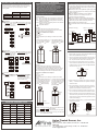
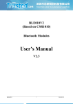
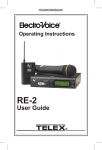
SPECIFICATION
Power supply
18~30Vdc
Measuring range
20~2000pF
20mA
Lower limit
4mA
HART
Option
LEVEL TR
NCE
AN
TA
SM
IT
M
D
R
TE
IT
Output
Upper limit
A
Output current 4~20mA (2 wire)
RF
EB5 Series
RF Admittance Level Transmitter
Operation Manual
DESCRIPTION OF PANEL
Linearity
A1%F.S. or A0.5pF
Load resistance
<(Vs-22)H50W
Vs: Power Voltage (volt)
-40BC~85BC
Environment
temperature
LCD monitor: -20BC~85BC
Thank for buying FineTek's products. Please
read the user manual first before using it. It
is important to be familiar with product's
performance and function. Please keep the
08-EB5XXX-B1-AM, 03/10/2014
user manual for operation reference.
Operation
temperature
According to the specification of probe
Environment
humidity
0~85% RH, non-condensing
Temperature
coefficient
LCD Display
range
<A0.2% F.S. per BC or 0.1pF per BC
-1999~9999
Protection degree
IP 65
CPU
Main SubMenu Menu
0~3
"Shift" button
Display value
DOT1 Decimal point setting
20mA corresponding
2sec
4mA corresponding
display value
Corresponding calibration value for
-1999~9999 100.0 high point (Hipt). See remark 1
Corresponding Calibration Value for
-1999~9999 0.0
low point (Lopt). See remark 1
-1999~9999 0
Voltage
regulator
SAVE,RSET
Memory for max & mini value
SAVE during
operation.SAVE:Save value
BACK
into Eeprom
REST:Clear present value and
SAVE,RSET
SAVE memoryBACK:Go back to sub-menu
BACK
Signal
output
Tank
Sensing probe
Lo,MID,HI
LO
Software Filter
ON, OFF
OFF
Output latch enable or disable.
See remark 2.
1~60sec
1
Output updated time
LO,MID,HI
HI
Measuring range remark 3.
Display current capacitance value
0~9999
DESCRIPTION OF PANEL
1. Button Protection, requiring to press ENT+UP
buttons for 2 seconds in order to get into main menu.
2. Three input buttons; user-friendly.
3. Any two points for calibration
4. Retention for maximum and minimum values.
PROGRAM SETTING FLOW CHART
Description
Default
-1999~9999 100.0 display value
24VdcA10%
RF Admittance
Level Transmitter
Range
0~9999
400
High point Capacity Value
0~9999
200
Low point Capacity Value
-1999~9999 0
4mA micro setting value
-1999~9999 0
20mA micro setting value
Default
Remark
Remark
Remark
Remark
1:
2:
3:
4:
Please refer to calibration procedure for HIPT & LOPT setting.
The output is latched when display is up to 110% or -10%
Re-calibration is essential when the measuring range is revised.
When calibrating 4 .20mA, 0.24uA per step will be changed
when press up bottom once.
PF & ACCURACY CHART
DESCRIPTION OF ALARM MODES
Error Message
Make sure the power supply 24V±10%
Display "1"
Recalibrate HIPT
Display "-1"
Recalibrate LOPT
Display "Over"
The capacitance is too much , please select plastic coating version,
or caused to short between probe and wall.
"SPAN" ,"WARN"Glisten
The output range is smaller than 20Pf, Adjust range to low level and recalibrate it
"LACH"
The output is latched , enter CTRL
Display "NULL"
Accuracy(%)
Correction
No Display
"1234"
"Enter" button
Power supply
"UP" button
DESCRIPTION OF PARAMETERS
WORKING PRINCIPLE
When the probe is surrounding by the air , little capacitance
(C A ) is measured by the equivalent capacitor , the
capacitance increase gradually as computing media, the
max. capacitance (C B) will be measured while the tank is
full, the difference (dC)between C A and C B is proportional to
the level.
(Recommend range dC =25 ~2000 pF)
OSC
LCD display
LACH to turn off this function
5.0%
1.0%
0.9%
0.8%
0.7%
0.6%
0.5%
0.4%
0.3%
0.2%
0.1%
0.0%
0 100
2000
2500
D:
E:
F:
I:
J:
K:
L:
N:
O:
P:
Q:
R:
S:
T:
U:
V:
W:
X:
Y:
Z:
There is shortcut between probe and tank wall, please recheck the installation
500
1000
1500
(PF)
The output change rapidly
when level disturbance
Increase "DAMP"value
The output change rapidly
when level is stable(<3%)
Set "FILT" to HI ,increase the frequence of filter
The output change rapidly
when level is stable(>3%)
1. Enter manu"CAP" to check if the value change
2.When level remains , but the value change <1pF , please recalibrate HIPT &LOPT
3.When level remains, but the value change >1pF , please recheck the wiring.
A:
B:
C:
The output is not porpotional
to the level
Try to calibrate at 0% & 100% , the accuracy is higher when the setting is closer to 0%&100%
G:
H:
The LCD Display low point but the
display on the Panel at control
is not equal low point
Enter the manu to E_4, If the display at the control room > low point , decrease
E_4 value ;if the display at the control room< low point , increase E_4 value
M:
The LCD Display high point but the
display on the Panel at control
is not equal high point
Enter the manu to E_20, If the display at the control room > high point , decrease
E_20 value ;if the display at the control room<high point, increase E_20 value
CODE
SETTING FLOWCHART FOR EACH FUNCTION
CALIBRATION PROCEDURES
WIRING AND CAUTION
Compact Capacitance Level Transmitter is to press the three
buttons (UP, SHIFT, ENTER) on display panel. Firstly, selecting
the setting menu then input value by using three buttons
showing below:
1.Read installation notice before calibration.
2.It is recommended to have the media touched probe
bottom when users calibrate lowest value for empty tank.
3.Doring calibration, pribe should be put into the tank.
Don't calibrate the product outside the tank.
4.Please keep at least 50% distance between HIPT and LOPT
to ensure accuracy. It is recommended to calibrate with
empty and highest level in the tank.
2 After installation of the Compact Capacitance LevelTransmitter on
the top of tank, please make sure the cover of the transmitter is
contacted with tank perfectly. Please avoid the grounding of panel
meter to touch the tank wall.
2 While the panel meter is not supplied with a power supply, please
prepare a 24V power supply for use. The wiring for panel meter is
showing in diagram 1.
2 The max cable length is depends on the max resistance.
Maximum resistance is not to exceed (Vs-15)H50W to
ensure the accuracy of measurement.
2 Make sure to separate the signal cable with other big power
cables (such as pump, conveyer and solenoid valve)while wiring.
Before turning on power, make sure all wirings are correct.
2 Connect isolation cable with GND of power.
2 Connect tank with heater or cover of electric device to decrease
EMI.
Selection
Setting
Up button
Escape button Increment button
SHIFT button
Enter button
Position shift button
ENTER button
Swap button
Confirmation button
Enter Button
●Swap Button is for swapping ●Confirmation button. After revising
to different menus, such as
the SCH value, press enter button
from main menu to main
to save the revised value.
menu or from sub menu to
sub menu.
Display value
1 2 34
1234
Flashing alternately
:Revise Parameters
:Save Parameters
Standard procedures:
1.SCH : Set the max display value corresponding to 20mA at SCH.
2.SCL : Set the min display value corresponding to 4mA at SCL.
3.HIPT : Input and save the corresponding value at HIPT, while the
medium is in high level.
4.LOPT: Input and save the corresponding value at LOPT, while the
medium in is in low level.
Completed Calibration
Example 1:
The lowest value sets at 0 and the output sets at 4mA.
The highest value sets at 100.0 and the output sets at 20mA
Calibration is done in empty and full tank.
Procedures of calibration for example 1
1.Input:
Dot=1, SCL=0.0
SCH=100.0,
(It can be adjusted anytime; Nothing is related with the status
of tank.)
2. When the tank is empty, go to 3. When the tank is full, go to
the LOPT setting and input 0.0,
HIPT setting and input 100.0,
then press "ENT"
"SAVE"
then press "ENT"
"SAVE"
(remark 1).
(remark 1).
SHIFT Button
Setting
value
Empty Tank
12 3 4
Flashing alternately
(Digit flashing means
the value is revisable.)
Setting
value
Setting
value
Setting
value
UP Button
●Up button is enable to escape ●Increment button. After entering
from revision mode or to
revise mode, press this button to
escape from sub menu to
increase the revisable value.
main menu.
For example, changing SCH
value from "1230" to "1234" is to
press this button fourth.
1230
1234
+24V
Panel meter
+24V
EXC 24V
1
2
1
3
A Input
Signal GND
EXC 24V
4
5
2
3
4
6
A Input
Signal GND
7
8
5
6
7
8
Warning
The Signal GND of panel meter should not be connected
with tank wall or the cover of the EB Transmitter, otherwise
the measurement will be incorrect.
INSTALLATION
1. Please install a concentric circles metal pipe shield with vent
hole at the top outside the probe (Fig. 1)
Full Tank
2. The rod or wire probe should be parallel to the tank wall. To
prevent material from sticking between the probe and tank
wall , the probe shouldn't be too close to the tank wall.
1234
Setting
value
(Diagram 1) Power supply
Panel meter
100%
20mA
●Shift Button is for entering a ●Position Shift Button. After entering
revision mode, press this button to
sub menu from main menu
shift into revisable position.
or doing a position shifting
after entering sub menu.
[ Description of wiring ]
4mA
0%
Example 2:
The lowest value sets at 100.0 and the output sets at 4mA.
The highest value sets at 200.0 and the output sets at 20mA
It is calibrated at 10% of tank high and 90% of tank high. The 0%
of the total height of the tank is corresponded to 4mA, while the
100% of the total height of the tank is corresponded to 20mA.
3. If the container is irregular-shaped, such as a cylindrical ,
and the medium is liquid with low viscosity, the rod should
be placed inside a concentric circles metal pipe shield with
vent hole at the top.(Fig. 1)
Tube
Procedures of calibration for example 2
1. Input:
Dot=1, SCL=100.0,
SCH=200.0
(It can be adjusted anytime; Nothing is related with the status
of tank.)
2. To fill the medium till reaching to 3. To fill the medium till reaching
to the 90% height of the tank,
the 10% height of the tank, go to
go to HIPT setting and input
the LOPT setting and input the
the value of 90.0 and then
value of 10.0 and then press
press "ENT"
"SAVE''
"ENT"
"SAVE'' (Remark 2).
(Remark 3).
Flashing alternately
Vent hole
Rod probe
(Fig. 1)
4. Coating Probe type is necessary for conductive media (eg.
Water...) , as the bare electrode can't operation normally in
conductive media.
5. During the installation, the process connection should be
grounded. An installation without proper grounding will not
guarantee normal operation of the device later on.
6. For non-conductive medium of powder or granules in big
tank , the wire probe should be fixed to the bottom of tank
Highest
point
90%
DIELECTRIC CONSTANTS CHART
7. When all electrical connections inside of Admittance Level
Transmitter housing are finished, the housing cover and the
conduit opening should be sealed and tightened to prevent
moisture from soaking in.
8. If an agitator is in place (see fig. 3), a pipe shield outside the
probe is recommended.
10%
Lowest point
Material
Air
Gasoline
Dielectric
Constant.
1
1.9
Material
Cement
Butanol
Dielectric
Constant.
wire probe
Isolate
supporter
4~6
11
Remark 1: Under the setting for Hipt & Lopt, press "ENT" to show
(screen flashing)
Press "ENT" button to save the value and then press "UP" button
to escape the setting.
Remark 2: When Hipt or Lopt setting is over range, the LCD show
"Err", Please reset the value.
Rod probe
Cable probe
Agitator
Ceramic
isolator
Diesel
2.1
Ethanol
16~31
Edible Oil
2~4
Ammonia
21
Heavy Oil
2.6~3.0
Acetone
20~30
Grain
2.5~4.5
Carbide
Powder
5.8~7.0
Corn
2.3~2.6
Sulfuric Acid 84
Aplus Finetek Sensor, Inc.
Rice
3~8
Water
California, U.S.
355 S. Lemon Ave, Suite D, Walnut, CA 91789; Tel : 1 909 598 2488
Illinois, U.S.
1741 Industrial Drive, Unit #3, Sterling, IL 61081; Tel : 815-632-3132
Email: [email protected]
81
http://www.aplusfine.com
(Fig. 2)
(Fig. 3)