1
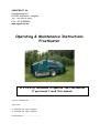
AGROFROST SA Canadezenlaan 62 B-2920 Kalmthout – Belgium Tel: +32 495 517689 Fax: +32 32958428 www.agrofrost.be Operating & Maintenance Instructions Frostbuster It’s strictly forbidden to operate the Frostbuster if you haven’t read this manual. Year of construction: ............... Type: F401 Machine for 4 gas cylinders Machine for 6 gas cylinders Serial number: .................................. ~2~ This manual has to be used according the European legislation. It has to be considered as a part of the machine. The manual has to be kept with the machine until the final dismantle as described in the European legislation. The purpose of this manual is to help use and maintain the Frostbuster safely. The user manual has to be kept by the owner or the user on a safe, dry and sun protected place on the working area. It must always be available to consult. When the manual is damaged, the user has to ask Lazo Europe for a new one. Copyright AGROFROST SA 2010. All rights are strictly preserved. Reprinting, coping, changing, republishing and disclosure is strictly forbidden by all means without recognition of Lazo Europe. Furthermore Lazo Europe has the rights to change this publication and fulfil changes to the content without preannounce of such changes or rework. Frostbuster - Operating & Maintenance Instructions – www.agrofrost.be ~3~ POINTS OF ATTENTION IN THIS MANUAL Hint: to give suggestions and advice to ease certain tasks Attention: Warning: a remark with extra information to call your attention for possible problems to call your attention for avoiding danger ABOUT THE USERS OF THE FROSTBUSTER Required user characteristics. Persons who are allowed to drive a tractor by law and are familiar with the driving of a tractor may operate the Frostbuster. They have to be at least 18 years old and be able of all their physical and psychical capacities. They must read this manual before using the Frostbuster. Someone who has not read this manual, cannot use the Frostbuster safely. The profile of the user. The user manual is created for two main groups: - The user / driver: the person who operates the Frostbuster - The mechanical maintainer: the person who does the assembling, maintenance and repairs They have to read this manual completely before using the Frostbuster are before doing any repairs or maintenance on the Frostbuster. Frostbuster - Operating & Maintenance Instructions – www.agrofrost.be ~4~ Index 1 SECURITY ....................................................................................................................... 5 1.1 1.2 1.3 1.4 1.5 1.6 1.7 1.8 2 TRANSPORT AND STORAGE ..................................................................................... 8 2.1 2.2 3 Installation. ................................................................................................................. 9 First use ...................................................................................................................... 9 Previous to the start procedure ................................................................................... 9 The control panel...................................................................................................... 10 Start procedure ......................................................................................................... 11 Start procedure without electronic ignition.............................................................. 12 The ideal circuit........................................................................................................ 14 During operation ...................................................................................................... 16 Replacing the gas cylinders or ending the operation................................................ 16 WHEN TO START / STOP – HOW DOES IT WORK – APPLICATIONS........... 17 4.1 4.2 4.3 5 Transport .................................................................................................................... 8 Storage........................................................................................................................ 8 INSTALLATION AND START-UP............................................................................... 9 3.1 3.2 3.3 3.4 3.5 3.6 3.7 3.8 3.9 4 Introduction ................................................................................................................ 5 The use in closed areas............................................................................................... 5 Safety and health risks................................................................................................ 5 Safety equipment........................................................................................................ 6 Safety precautions before use..................................................................................... 6 Safety precautions during use .................................................................................... 7 Safety precautions when ending operation and changing the gas cylinders .............. 7 Safety advice on maintenance, repairs and storage.................................................... 7 When to start and to stop.......................................................................................... 17 How does it work. .................................................................................................... 17 Different Applications.............................................................................................. 17 MAINTENANCE – CLEANING.................................................................................. 18 5.1 5.2 5.3 5.4 Burner....................................................................................................................... 18 Gas hoses.................................................................................................................. 18 Fan and Transmission............................................................................................... 18 Cleaning ................................................................................................................... 18 6 EXPLANATION PICTOGRAMS................................................................................ 19 7 WARRANTY - SCRAPPING – SPARE PARTS LIST.............................................. 20 7.1 7.2 7.3 Warranty................................................................................................................... 20 Scrapping.................................................................................................................. 20 Spare parts list. ......................................................................................................... 20 8 EC DECLARATION OF CONFORMITY.................................................................. 21 9 INSTALLATION PROCEDURE................................................................................. 24 Frostbuster - Operating & Maintenance Instructions – www.agrofrost.be ~5~ 1 Security 1.1 INTRODUCTION In this chapter, the Frostbusters most important safety aspects will be explained. It is essential that everybody who works with the Frostbuster goes through the contents of this chapter attentively. The most important safety and health risks related to using the Frostbuster, are listed in paragraph 1.2. The Frostbusters safety equipment is described in paragraph 1.3. The safety precautions to be taken by the Frostbuster user come up in paragraphs 1.4 to 1.6, and the symbols found on the Frostbuster are clarified in paragraph 1.8. 1.2 THE USE IN CLOSED AREAS It is not allowed to use the FrostGuard in a closed area, because of three reasons: 1. The engine and burner consume a lot of oxygen. So the supply of fresh air is very important. 2. The engine of the tractor produces carbon monoxide, an odorless, colorless, poisonous gas. Breathing carbon monoxide an cause nausea, fainting or death. 3. If gas would escape because of a gas leak, it would create life threatening situations in a closed area because of the danger of explosions. 1.3 SAFETY AND HEALTH RISKS The following safety- and health risks related to using the Frostbuster, have to be given attention: Forward tilting during coupling Presence of a drive shaft Presence of a gas installation High temperatures around nozzle and exhausts Risk of explosion in closed space Lighting the pilot when the gas valve is open Uncontrolled use of the Frostbuster The Frostbuster is designed to reduce these risks as much as possible. The safety equipment used to achieve this are listed in paragraph 1.3, the safety precautions to be observed are listed in paragraph 1.4. Frostbuster - Operating & Maintenance Instructions – www.agrofrost.be ~6~ 1.4 SAFETY EQUIPMENT To make the use of the Frostbuster as safe as possible, the following safety equipment is delivered with the machine: *Covering the exhaust pipes isn’t possible because these exhausts are needed for applying a air flow circulation. Because of this, it is possible a grown up puts his hand in the exhaust and is able to reach the blade wheel of the fan. We can only apply the necessary safety stickers to prevent such an act. Additional, the user cannot allow any other persons in the safety zone of 30 meters arround the machine. Thanks to this manual, he also has to be alerted extra for danger. EXTRA WARNINGS: DO NOT PUT YOUR HANDS IN THE EXHAUST FAN When the optional wheel set is installed, the Frostbuster is equipped with a front leg, preventing the Frostbuster to tilt forward. The nozzle is isolated with glass wool, both to reduce the noise and to prevent the sides from overheating. By using the manual gas valve at the back of the machine as a lock for the back guard, the user cannot light the pilot while the gas valve is open. An electric valve is built in. This valve has to be opened manually, and it stays only open automatically by the heat sensors after ± 30 seconds. When the energy supply is cut off, the machine cannot function, because the pilot will have gone out. Various safety components are built in the gas installation. These have been inspected by an official inspection service. Risk of explosion has been averted completely by the safety components and the explicit ban on indoor use. Various lights on the control panels simplify the operation of the Frostbuster. All moving parts are screened completely, in order to avoid contact during normal operation. A fixed safety zone of 30 meters around the Frostbuster has to be observed: no other people but the user may be in that safety zone. The sheets that keep the gas cylinders on their place are equipped with handles, so it is very simple to pick them up and hold them. 1.5 SAFETY PRECAUTIONS BEFORE USE First read attentively the instructions in the manuals of both the Frostbuster and the tractor. The user has to be acquainted with operating the controls of both. The guards must all be in their place. The Frostbuster cannot be used, when one or more of the following guards are missing, loose, damaged or incomplete: the complete drive shaft protection; the guard on the PTO shaft; the tightening belts has to be mounted always so the gas bottles cannot move. Furthermore, the following safety equipment has to be present: the supplementary gloves, the face protection, the leak spray and the wooden matches Check the gas connections for leaks. Check the burner ring holes: if they are clogged, clean them with a dry, clean cloth. They can also be blown with compressed air. Frostbuster - Operating & Maintenance Instructions – www.agrofrost.be ~7~ 1.6 SAFETY PRECAUTIONS DURING USE Be extremely careful when there are obstructions blocking your view. When the machine is activated, make sure that nobody is within the safety zone, being 30 meters around the machine. If you need to leave the tractor for a moment due to unforeseen circumstances, keep the PTO shaft running at a stable pace. When the number of revs lowers, the exhaust temperature will rise sharply. The guards on the exhausts will also heat up enormously, with potential danger of burns. Do not stop between the trees. 1.7 SAFETY PRECAUTIONS WHEN ENDING OPERATION AND CHANGING THE GAS CYLINDERS Keep the ventilator running for at least 3 minutes, so the heat sensors can cool sufficiently. The sheets that keep the gas cylinders on their place are equipped with handles, so it is very simple to pick them up and hold them. Use the leak spray to check the connections of the gas cylinders for leaks. USE OF THE MACHINE WHITOUT THE USE OF TIGHTENING BELT IS STRONGLY PROHIBITTED. Always close the gas bottles after use, and also before changing them on the machine. 1.8 SAFETY ADVICE ON MAINTENANCE, REPAIRS AND STORAGE All screws and nuts must be tightened firmly, in order to keep the machine safe and in optimal condition. The Frostbuster must not be stored with gas cylinders on it. Always use genuine spare parts. Using non genuine spare parts can enhance the chances of damage, even if they fit on the machine. Replace damaged warning and instruction stickers. Store the Frostbuster horizontally in a dry place All the flexible gas hoses has to be replaced every 5 years. Frostbuster - Operating & Maintenance Instructions – www.agrofrost.be ~8~ 2 Transport and Storage 2.1 TRANSPORT - Make sure that the fastening pins of the tractor’s 25 mm lift plate are removed. Back the tractor, in order to get the lift plate in front of the machine’s connection. Make sure that the lift plate is on the right level: between both plates of the connection of the Frostbuster. Back the tractor in order to make sure that the fastening pin can be put through the holes in the connection and the one in the lift plate. After the pin is put in place, the foot at the front of the machine can be removed. 2.2 STORAGE Because the moment the Frostbuster has to be used is never known a long time in advance, the Frostbuster has to be stored as if it were not used for a long time. Make sure that the Frostbuster is cleaned as described in chapter 6. Store the Frostbuster on a covered, dry place and preferably horizontally. The gas cylinders have to be removed every time the machine is put away. The gas cylinders have to be stored outside, according to the prescriptions of the fire insurance company, while the Frostbuster has to be stored indoors. Frostbuster - Operating & Maintenance Instructions – www.agrofrost.be ~9~ 3 Installation and Start-up. 3.1 INSTALLATION. Mount all the pieces that are delivered separately. Make sure that you always use the straps to place the bottles into place. If there are not fixed properly, they can start turning around which may cause the breaking of the gas hoses. 3.2 FIRST USE When the Frostbuster is coupled for the first time, the drive shaft has to get extra attention. Possibly, the accompanying drive shaft is too long or too short for the tractor – Frostbuster combination: the drive shaft still has to be well connected, when the machine is lifted (see the manual of the drive shaft). Should it be too short, it has to be replaced by a longer one. If there is not enough space for the drive shaft to move, the drive shaft has to be shortened. You can do this best by following carefully the instructions in the manual about disassembling and shortening the drive shaft 3.3 PREVIOUS TO THE START PROCEDURE 1. Check if the tractor is completely in working order. In order to obtain optimal results, the tractor cannot be defective. That is why it is important for you to check if there are no clogged filters, that there is enough fuel in the tank, and that the PTO controls work properly. 2. Supply enough spare gas cylinders. Make sure that these are within easy reach, so changing them can be done as quickly as possible. Put the necessary tool out as well: a 28 mm open end spanner. (In some countries, the open end spanner maybe of a different size as 28 mm) 3. Attach the Frostbuster to the tractor as described in chapter 2. 4. Check the gas connections with the leak spray and check the manual main valve at the front of the machine, which should be closed. 5. If the control box is not installed yet, it has to be put on the correct place, and the plug has to be connected to the tractor. The control box must always be in the direct view of the driver, within arm’s reach and well fixed. 6. Switch off the emergency stop by turning it in the direction of the arrows until you cannot turn it any more. Also check if the main switch is in the ‘zero’ position. 7. Make sure that the PTO is ready. It has to be on, but the clutch still has to be in neutral. Frostbuster - Operating & Maintenance Instructions – www.agrofrost.be ~ 10 ~ 3.4 THE CONTROL PANEL 2 3 4 1 9 10 12 13 11 1 Main switch 2 Red light 3 Green light 1 4 Green light 2 6 Yellow light 1 7 Yellow light 2 9 Thermometer 10 Manual switch S1 11 Blue light 12 Emergency stop 13 Fuse 6 7 = with this switch the Frostbusters electric circuit is switched on = if this indicator light is on, the machine’s electrical circuit is switched on = if this indicator light is on, the electric valve is closed = if this indicator light is on, the front manual valve is closed = if this indicator light is on, the electric valve is open = if this indicator light is on, the front manual valve is open = indicates the current operating temperature = this switch controls the electric valve and has to be kept in turned position until the valve remains open automatically (as long as blue light 11 is not on) = if this indicator light is on, the electric valve on the machine is kept open automatically by the heat sensors and switch 10 can be released = must be pressed if any case of an emergency: the electric valve will close immediately and the burning process will be stopped = protects the electric circuit against short-circuiting Frostbuster - Operating & Maintenance Instructions – www.agrofrost.be ~ 11 ~ 3.5 START PROCEDURE It is very important that the start procedure is done by just one person. Several persons working together to start up the machine can be extremely dangerous. 1. Start the tractor. 2. Switch the main switch to position 1, or up. The red check light will light up. If it doesn’t, check the plug that connects the control block to the tractor. The 2 green check lights next to the red one will light up as well: this indicates that the main switch at the front is closed. If that is not the case, please close it. 3. Open all the gas cylinders. 4. Open the manual main valve at the front. Make sure that all gas cylinders are opened completely. 5. After checking the minimum safety distance of 30 m around the machine for the presence of other people, get back on the tractor. One of the two yellow lights on the control panel should be on now. If not, check again if the manual main valve is open. 6. Turn the switch S1 on the control panel to the right for one second, release it and turn it right again and keep it in switched position. The electric valve opens and the burner will start to burn. If that does not happen within 3 seconds, you have to release the switch, let the PTO turn to blow away the gas and resume the start procedure as T S1 EB from point 5. If there is a problem with the electronic ignition, go to chapter 3.6. There you find instructions to start the machine without the electronic ignition. 7. As soon as the burner starts to burn, the PTO has to be started. Accelerate gradually the PTO to a maximum of 540 rpm. 8. As soon as the blue warning light on the control panel is lit, you can release the switch S1. The blue light indicates that the electric valve remains open automatically and that the machine is secure. 9. The working pressure of the gas has to be regulated so that the temperature of 85°C-100°C is reached. The first 20 seconds, the thermometer will read the same, but will then climb to 60-70°. At 540 rpm, the normal working pressure will be between 1,2 and 1,6 bar. However, this may change and depends also on air temperature, humidity, wind etc. At a lower number of revolutions, the working pressure will be lower. 10. If the temperature exceeds 120 °C, you have to push the emergency button (EB) immediately to stop the burner. Let the PTO turn for a few minutes until the machine has cooled down, lower the gas pressure and start again from point 5. Frostbuster - Operating & Maintenance Instructions – www.agrofrost.be ~ 12 ~ 11. Check the temperature constantly and adjust the gas pressure in order to obtain an air temperature between 85 and 100 °C. If the temperature remains stable for a few minutes, you start driving through the orchard etc. 12. When the Frostbuster is operational, the speed of the ventilator must not be raised or lowered under any circumstances. This means that the drive shaft must run at stable pace. Every change will have an immediate effect on the temperature. If the temperature exceeds 140 °C, the sensors that control the electric valve and the temperature meter may burn. In that case, operating the Frostbuster will be impossible. There is an emergency stop on the control panel next to the driver. If there is any doubt, this switch has to be pressed. All gas supply will then be cut off immediately. When the Frostbuster is operational, the speed of the ventilator must not be raised or lowered under any circumstances. This means that the drive shaft must run at stable pace. Every change will have an immediate effect on the temperature. When disconnecting the gas supply, for any reason, always keep the machine running for another 3 minutes in order to remove any amassed gas and to cool down the heat sensors of the electric valve. Only then other people may enter the safety zone. When the Frostbuster is transported, the gas cylinder valves must be closed all the time. A few more points of interest: Start the drive shaft gradually. All safety precautions described in chapter 1 have to be observed. When the temperature on the control panel drops 20 degrees in a few minutes, the gas cylinders will have to be replaced. In that case, the time schedule can be interrupted for a few minutes without possible damage to the plants. It is of course recommendable to keep the replacing time as short as possible, and below 10 minutes. 3.6 START PROCEDURE WITHOUT ELECTRONIC IGNITION It is very important that the start procedure is done by just one person. Several persons working together to start up the machine can be extremely dangerous. 1. Start the tractor. Frostbuster - Operating & Maintenance Instructions – www.agrofrost.be ~ 13 ~ 2. Switch the main switch to position 1, or up. The red check light will light up. If it doesn’t, check the plug that connects the control block to the tractor. The 2 green check lights next to the red one will light up as well: this indicates that the main switch at the front is closed. If that is not the case, please close it. 3. Open all the gas cylinders. 4. Be sure to wear the face protection and the gloves, which are supplied with the machine. An unexpected flare could cause burns or set clothes on fire. 5. Remove the protective hood only when the 2 green check lights (A) are on, and when you are wearing the protective equipment. If one of the green lights is not on, there is a possibility of gas leakage in one of the gas pipes. Remove the hood (B), light the Bunsen burner (C) and put it into the tube that leads to the burner. A A B C 6. Open the manual main valve at the front. Make sure that all gas cylinders are opened completely. 7. After checking the minimum safety distance of 30 m around the machine for the presence of other people, get back on the tractor. One of the two yellow lights on the control panel should be on now. If not, check again if the manual main valve is open. 8. Turn the switch S1 on the control panel to the right and keep it in switched position. The electric valve opens and the burner will start to burn. If that does not happen within 3 seconds, you have to release the switch, let the PTO turn to blow away the gas and resume the start procedure as from point 7. T S1 EB 9. As soon as the burner starts to burn, the PTO has to be started. Accelerate gradually the PTO to a maximum of 540 rpm. 10. As soon as the blue warning light on the control panel is lit, you can release the switch S1. The blue light indicates that the electric valve remains open automatically and that the machine is secure. 11. To proceed, see chapter 3.5 – point 9 but don’t forget to take out the Bunsen burner and to replace the hood. Frostbuster - Operating & Maintenance Instructions – www.agrofrost.be ~ 14 ~ 3.7 THE IDEAL CIRCUIT a. The distance between the rows you drive through must be between 50 and 100 meters. 50 to 80 meters is ideal. b. If possible, drive not always through the same row, but take once the row at the left, once the main row, and next the row at the right, so you have three rows to drive through. This is better for the air distribution, will cause less drying of the flowers and will keep the soil in better condition. If the row distance is more than 4 meters, you can use 2 rows instead of 3. c. If possible, make two circuits that you drive alternately. This second circuit has to pass in the middle of first one, or at least 25 meters more to the left or right of the first circuit. Take a look at the example in the next page. d. The total distance of the circuit may not be longer than 1300 meters. If you drive two circuits, the total distance of the two must stay under 2600 meters. e. The driving speed has to be between 4 and 8 km/H and has to be chosen in a way that one circuit lasts between 7 and 10 minutes. 8 to 10 minutes is ideal. This is because the protection is partly caused by the fluctuations of the temperature. Examples: i. Circuit = 1000 meters, speed = 6 km/H, time = 10 minutes ii. Circuit = 800 meters, speed = 6 km/H, time = 7,5 minutes iii. Circuit = 800 meters, speed = 5 km/H, time = 9,6 minutes iv. Circuit = 1300 meters, speed = 8 km/H, time = 9,8 minutes f. Mark the rows where you want to drive through, so it will be easier to follow the circuit in the dark. g. Make a test drive with the machine, with the gas bottles mounted, the fan operating and with the burner NOT operating. This is important for two reasons: to check the time of the circuit (see point 1.f), and to check if the Frostbuster stays stable during the complete circuit. Eventually, increase the distance between the wheels, so the stability will improve. It is extremely important that the Frostbuster cannot turn over, because of uneven, rough ground or because of the inclination of the terrain. To calculate the ideal circuit, please send a fax (+32 32958428) to the manufacturer, containing an exact drawing on scale of the orchard, with all the dimensions, directions of the rows, distance between the rows and mark the places where it is impossible to drive through. Or send an e-mail: [email protected] Frostbuster - Operating & Maintenance Instructions – www.agrofrost.be ~ 15 ~ 180 m 30m 90m 30m = start = 1st tour 30m = 2nd tour 300 m 90 m Frostbuster - Operating & Maintenance Instructions – www.agrofrost.be ~ 16 ~ 3.8 DURING OPERATION During operation the PTO’s speed must not be raised or lowered. A change of speed will cause the temperature to rise or fall inversely proportional to the PTO’s speed. Consequently operation will be less efficient. If the flame should go out for any reason during operation, it must not be lit immediately. First, the ventilator must run for minimally 3 more minutes, so the heat sensors can cool down and the electric valve will close automatically. If the ventilator has been kept running for only a few minutes, the heat sensors of the electric valve may heat up by the presence of latent heat. This can cause danger for burns if a second person opens the front manual valve before the person, who lit the flame, can get away from the back of the machine. 3.9 REPLACING OPERATION THE GAS CYLINDERS OR ENDING THE The procedure for replacing the gas cylinders is equal to the procedure for ending the operation of the Frostbuster. The correct procedure is the following: 1. Turn off the power to the Frostbuster by switching off the main switch. 2. Close the manual main valve at the front of the machine. 3. Close all the valves of the gas tanks. 4. Keep the machine running for at least 3 more minutes, then switch off the PTO. 5. Disconnect the gas tanks and store these outside. If you need to continue working with the Frostbuster, new cylinders can be connected to the machine. In order to start the Frostbuster again, the start procedure has to be followed again. Frostbuster - Operating & Maintenance Instructions – www.agrofrost.be ~ 17 ~ 4 When to start / stop – How does it work – Applications. 4.1 WHEN TO START AND TO STOP. In case of night frost, you have to start operating when the wet temperature reaches 0° C. The machine has to work for about 1 hour before it will create a positive effect on the temperature and the humidity. As soon as the temperature outside the orchard is positive again, you can stop. Measuring the wet temperature: place a plastic foil of 1 square meter on the ground, on the lowest (and coldest) point in the orchard. Place the temperature sensor on the foil. Start as soon as the temperature indicates 0° C. A good night frost alarm is necessary. 4.2 HOW DOES IT WORK. There are 3 factors that make both machines work: The increase of temperature. The very important creation of temperature fluctuation: At each passing of the Frostbuster or the outlet of the FrostGuard, the temperature rises a small amount and drops again. The big advantage of creating fluctuations is that this requires much less energy than raising the temperature above the critical values constantly. Therefore, the input of energy is up to 7 times less than with other systems. The largest damage during a night-frost is caused by ice crystals. Wherever the FrostGuard or Frostbuster are used, the relative humidity goes down. Because of this, the dew point is postponed significantly. And therefore, also the forming of ice crystals will start much later and will be much less. Result: no or very low damage 4.3 DIFFERENT APPLICATIONS. The Frostbuster can be used almost everywhere and for several applications: For frost protection in orchards for all kind of fruits, in vineyards, in greenhouses and plastic tunnels, for strawberries, raspberries, flowers, vegetables, apples, pears, peaches, plums etc. 2) To improve the fruit set in low temperature during blossom. 3) To raise the temperature in plastic tunnels, to bring forward the first harvest date in the beginning of the season, or to pick later at the end of the season Frostbuster - Operating & Maintenance Instructions – www.agrofrost.be ~ 18 ~ 5 Maintenance – Cleaning 5.1 BURNER. The burner does not require any maintenance. 5.2 GAS HOSES The gas hoses have to be replaced every 5 years. 5.3 FAN AND TRANSMISSION. The maintenance of the Frostbuster is very simple: you only have to pay attention to the following points: Every 10 working hours, the bearing at the front of the machine has to be greased. The drive shaft has to be greased as prescribed in the manual that is delivered with the drive shaft. At the beginning of the season, the tyre pressure has to be checked and adjusted when necessary. After 200 working hours, or every two years in case less than 200 working hours are performed, the oil of the gearbox has to be changed. Type of oil: 80W90. Quantity: ± 1,5 litres. If the Frostbuster is not stored on a dry place, it is recommended to inspect the inside of the machine in the third or fourth season. The glass wool could absorb water from the air and hold it, causing the perforated plate to rust. When this occurs for a long time, the machine could blow out pieces of the perforated plate. Check the tension of the belts every 10 working hours. 5.4 CLEANING There are no specific rules for cleaning the Frostbuster. In normal conditions, the functioning of the Frostbuster will not be obstructed by dirt or impurities. Of course, a touch-up is always useful for the Frostbuster. The best time is right before use after a long time. When starting the machine, the user should only check if the holes in the burner ring are not clogged. To go over the holes with a dry, use clean cloth or some paper towels. Frostbuster - Operating & Maintenance Instructions – www.agrofrost.be ~ 19 ~ 6 Explanation pictograms FLAMMABLE MATERIALS CAUTION DANGER HOT SURFACE SAFETY GLOVES MANDATORY MOVING PARTS FIRE: OPEN FLAMES AND SMOKING PROHIBITED 150m Frostbuster - Operating & Maintenance Instructions – www.agrofrost.be ~ 20 ~ 7 Warranty - Scrapping – Spare parts list. 7.1 WARRANTY. The warranty covers the parts that are defective from the start, and that are produced by LAZO EUROPE. This warranty expires when it is a matter of normal wear, when a malfunction is caused by incorrect operation or maintenance of the machine, in case the user has not observed the instructions in the manual, or when non genuine parts, not produced by AGROFROST are used. We do not accept complaints about changes that will be introduced in the future, in order to improve the machine. It is important that the document, called “INSTALLATION PROCEDURE” is filled up and send back to the address of the manufacturer: AGROFROST NV Canadezenlaan 62 2920 Kalmthout - BELGIUM . If this document is not send back, the manufacturer reserves the right to cancel any warranty. 7.2 SCRAPPING. The following table gives an overview of the correct way of disposal of the different parts, in case the Frostbuster has to be dismantled. Part Bearings Oil from the gearbox Synthetic guard on the PTO shaft Frame Screws, bolts, washers Gaskets Way of disposal scrap chemical waste container for synthetic material scrap scrap container for synthetic material 7.3 SPARE PARTS LIST. If you need a spare parts list, you can ask for it at the manufacturer. Send an e-mail to : [email protected] !! Frostbuster - Operating & Maintenance Instructions – www.agrofrost.be ~ 21 ~ 8 EC Declaration of Conformity. Declaration of Conformity. We declare under our own responsibility that the machine complies with the safety and health requisities established by the European Directive 2006/42/EG. Manufacturer Address : : Agrofrost SA Canadezenlaan 62 – 2920 Kalmthout Belgium Authorized representative Address : : Stynen Patrik Canadezenlaan 62 – 2920 Kalmthout Belgium Machine : Frostbuster Type F401 Serial number : ………………………. Signature: Patrik Stynen Frostbuster - Operating & Maintenance Instructions – www.agrofrost.be ~ 22 ~ Frostbuster - Operating & Maintenance Instructions – www.agrofrost.be ~ 23 ~ Frostbuster - Operating & Maintenance Instructions – www.agrofrost.be ~ 24 ~ 9 Installation procedure Installation procedure – copy for the client. CUSTOMER DEALER Name: ………………………… Name: ………………………… Address: ………………………… Address: ………………………… ……………………….. ……………………….. ………………………… ………………………… technician:……………………………. MODEL 401 Date:……………………… SERIAL NUMBER ............................ CHECK LIST & DEMONSTRATION PROCEDURE (To be carried out by the technician and the customer) Demonstration: Start up of the machine. The control panel. Handling of the machine. Precautions and safety measures to be respected: Gas connections (Leak spray). Safety measures delivered with the machine. The safety switch The user manual. Changing the gas tanks Storage and transport of the machine and gas tanks if not in use. Additional information according to the use on a specified terrain and the principle of working. INSTALLATION PROCEDURE COMPLETED I have received the Lazo Frostbuster in satisfactory condition and have received operating and safety training to my satisfaction. Technician signature…………………….. Customer Signature……………………………………... Name in Capitals…………………………. Name in Capitals: ………………………………….. Date………………………………………. Frostbuster - Operating & Maintenance Instructions – www.agrofrost.be ~ 25 ~ Installation procedure – copy for the dealer. CUSTOMER DEALER Name: ………………………… Name: ………………………… Address: ………………………… Address: ………………………… ……………………….. ……………………….. ………………………… ………………………… technician:……………………………. MODEL 401 Date:……………………… SERIAL NUMBER ............................ CHECK LIST & DEMONSTRATION PROCEDURE (To be carried out by the technician and the customer) Demonstration: Start up of the machine. The control panel. Handling of the machine. Precautions and safety measures to be respected: Gas connections (Leak spray). Safety measures delivered with the machine. The safety switch The user manual. Changing the gas tanks Storage and transport of the machine and gas tanks if not in use. Additional information according to the use on a specified terrain and the principle of working. INSTALLATION PROCEDURE COMPLETED I have received the Lazo Frostbuster in satisfactory condition and have received operating and safety training to my satisfaction. Technician signature…………………….. Customer Signature……………………………………... Name in Capitals…………………………. Name in Capitals: ………………………………….. Date………………………………………. Frostbuster - Operating & Maintenance Instructions – www.agrofrost.be ~ 26 ~ Frostbuster - Operating & Maintenance Instructions – www.agrofrost.be ~ 27 ~ Installation procedure – copy for the manufacturer. CUSTOMER Name: Address: DEALER ………………………… ………………………… ……………………….. ………………………… technician:……………………………. MODEL 401 Name: Address: ………………………… ………………………… ……………………….. ………………………… Date:……………………… SERIAL NUMBER ............................ CHECK LIST & DEMONSTRATION PROCEDURE (To be carried out by the technician and the customer) Demonstration: Start up of the machine. The control panel. Handling of the machine. Precautions and safety measures to be respected: Gas connections (Leak spray). Safety measures delivered with the machine. The safety switch The user manual. Changing the gas tanks Storage and transport of the machine and gas tanks if not in use. Additional information according to the use on a specified terrain and the principle of working. INSTALLATION PROCEDURE COMPLETED I have received the Lazo Frostbuster in satisfactory condition and have received operating and safety training to my satisfaction. Technician signature…………………….. Customer Signature……………………………………... Name in Capitals…………………………. Name in Capitals: ………………………………….. Date………………………………………. This copy has to be send back to the manufacturer. If this document is not send back, the manufacturer reserves the right to cancel any warranty. Send to : AGROFROST SA – Canadezenlaan 62 - B-2920 Kalmthout (Belgium). The address is already printed on the back side. Frostbuster - Operating & Maintenance Instructions – www.agrofrost.be ~ 28 ~ AGROFROST SA Canadezenlaan 62 B – 2920 Kalmthout Belgium Frostbuster - Operating & Maintenance Instructions – www.agrofrost.be