1
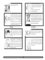
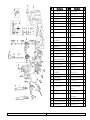
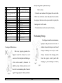
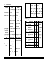
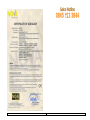
SX-MD16E Electric Sprayer
Notice to Users
User Manual
This User Manual is a part of the Sprayer. Please keep
it in good condition. In order to utilize and maintain the
product in good working order, please read the User
Manual carefully before operation. If you have any doubts
contact the supplier.
The Sprayer should be operated, maintained and
repaired by persons who are familiar with its performance
and know how to operate it in a safe manner.
The manufacturer shall not be liable for decreased
reliability, machine damage and human injury arising from
unauthorized modification of the Sprayer.
I.
Table of Contents
I.
Product Overview………………………………
II.
Structure and Features…………………………
III.
Technical Parameters…………………………
Product Overview
This is a highly-efficient rechargeable sprayer, suitable for
applying pesticides, fertilizers and chemicals for
controlling weeds and pests in crops, flowers
and gardens. The Sprayer is suitable for the sanitizing of
livestock and poultry houses, epidemic control and
IV.
Pre c a ut io ns … … … … … … … … … … … … …
sanitation of public places.
V.
How to Operate the Sprayer……………………
VI.Recommended pesticide and spray head operation
VII.Structural Diagram and Schedule…………………
VIII. Cleaning and Maintenance………………………
IX . St o ra g e … … … … … … … … … … … … … … … …
Ⅹ . Tro ub le s ho o t i n g … … … … … … … … … … … …
Ⅺ. Packing List ………………………………………
Powered by a 12V/7Ah battery, this sprayer saves time
labor and is up to 3 - 4 times more efficient than a manual
sprayer.
This sprayer can be operated continuously for up to 6
hours and spray 75 gallons of liquid after one full
Charge (based on a new battery).
II. Structure and Features
Structure: This sprayer consists of a tank, base, battery,
mini-pump, charger, spraying system, volt meter, rubber
④ A voltmeter and low-battery alarm circuit for precise
and clear indication of battery voltage. The alarm will
give an audible warning when the battery voltage falls
below 11V, to indicate the battery requires recharging.
tubes, switch, spraying lance, nozzles and straps, and
The sprayer should be switch off to prevent
trailer.
over-discharging to extend the service life of the
Features:
battery.
① The spray tank is ergonomically designed to fit the
⑤ Supplied with a dedicated three-stage battery charger
human back comfortably or capable of connecting with
(constant current, constant voltage, float maintaining)
the trailer for easy towing, it’s easy to assemble and
The indicator lamp : red — charging ; green —
disassemble.
full/stand-by (Never switch off at mains and leave
② Fitted with a high-pressure large flow pump to work
with nozzles of various functions, the atomization
charger connected to the Sprayer) this can shorten
service life of the battery.
pressure is between 2-4.5 bar, to suit the demands of
⑥ Designed to be low fatigue and user-friendly, the
many application types, with various nozzles to
sprayer can be carried on your back or wheeled on its
maximize productivity and cost-savings.
trailer. The trailer features a telescopic handle that can
③ Equipped with a compact light weight, high pressure,
diaphragm pump for even atomization and overload
protection to extended service life.
be varied depending on the user height for easy
operation.
1. Never spray flammable liquid of any kind;
III. Technical Parameters
2. Observe the Safety Instruction given by chemical
Knapsack and Wheeled trailer
1. Type:
manufacturers before operating the Sprayer.
2. Overall Size : 340•300•730mm
(trailer:2.2kg)
8.3kg
3. Net Weight:
Hazards
You are required to read this Manual and follow
the instructions for safe operation.
4. Capacity of Tank:16L
Micro diaphragm pump
5. Pump:
Working Pressure :
2.0~4.5 bar
limit of pump pressure: 4.5-5.0 bar
6. battery :12V7Ah SLA(fully-enclosed,maintenance free)
7. Charger: Input AC100-240V~50/60Hz
Output 12V DC
1.3A
Spraying nozzle
Pressure
Flow
Spraying nozzle
Pressure
Flow
type
bar
L/min
type
bar
L/min
Cone spraying
nozzle
3.0~4.5
0.70~0.90 Fan spraying nozzle
0.20~0.40 0.60 ~1.10
Double spraying
nozzle
2.5 ~4.0
1.30 ~1.60
Four-hole adjustable
spraying nozzle
0.20~0.40 0.60 ~1.10
IV.Precautions
● In addition to strictly following the safety instructions given in
the Manual, the operator is required to :
The operator should wear a respirator mask,
safety glasses, protective hat, protective
clothes, water-proof gloves and rubber boots
etc. during filling and spraying.
Storage and maintaining of pesticide.
Chemicals should be kept out of the reach of
children. For safe disposal of pesticide
containers follow the safety instructions issued
by the chemical manufacturer.
Disassembly and repairing of charger by
non-professionals is prohibitted . In case of
failure, please contact the distributor.
No servicable parts inside!
In case of inhaling dangerous chemical vapor
or direct contact with skin, seek medical
attention immediately! Be sure to inform the
medical professional of the type of chemical
involved.
Never spray at human beings, pets or animals.
Never spray against adverse wind.
Never dispose of used batteries in a fire or
household waste. Used batteries should be taken
to a recycling centre for recycling or proper
disposal.
Visit www.recycle-more.co.uk to find
your local recycling centre
The residual chemical should be kept in a
container and never poured onto the ground,
drains or rivers. The empty chemical containers
and bags should be disposed of safely in
accordance
with
the
Manufactures
recommendations or sent to the manufacturer
for proper disposal. Keep chemical containers
away from living areas and water sources.
Under the WEEE Regulations, all new electrical
Warning
Persons affected by fatigue, poor health, injury,
pregnancy or pesticide allergy or should never
engage in pesticide dispensing. Never consume
alcohol immediately after spraying noxious
chemicals.
Never use strong acid, strong alkalines, and
inflammable solutions; Never use highly-toxic
and highly-persistent pesticide for pest control of
vegetables, melon crops, fruit trees, etc. Ensure
enough time after pesticide application before
harvesting time. Contact chemical company for
suitable time infomation.
goods should now be marked with the crossed-out
wheeled bin symbol should be sent for recycling.
Retailers are obliged under these regulations to
offer customers free take-back of their WEEE on
a like-for-like basis when they buy a new
Electrical or Electronic product.
Precautions
The chemicals for application in this Sprayer
should not exceed 45OC. Operation in an
ambient temperature of 450C or below -100C
should be avoided.
Always carry out Trial spraying with clean
water, to check the various joints for possible
leakage, also a check nozzle for required
atomization conditions prior to initial operation.
Make sure everything is ok before preparing the
chemical liquid.
The preparation of chemicals should follow
the instructions and formula published by the
chemical manufacturer. Unauthorized altering
of the dilution rate of chemical is prohibited,
and may endanger human and animal health,
or result in the failure of sprayer or pest
control.
Upon completing the operation, it is
recommended you change your clothes and
wash exposed body parts such as hands and
face. In case of highly toxic pesticides and
germicide, its recommended to shower after
operation to ensure safety.
before being delivered. But due to self-discharge during
transportation and storage, please check the power level
with a voltage meter before operation. If the indicator stays
in yellow or red area, (i.e.≤12V, a supplementary charging
is required.
The battery can be charged by switching off the pump
plugging the charger’s plug
into the charging socket (Fig
2) on side control panel.
When the charger indicator
V.How to Operate the Sprayer
LED turns from RED to
Fig. 2
1. Operation of Charger
GREEN, it indicates that the
battery has been fully charged.
Make sure that the
input voltage of the
A GREEN LED can also indicate the charger is on standby
charger complies with
or not connected.
the AC parameters of
The no-load voltage of full-power battery is 13.8V.
mains supply. If in
Never leave the charger connected to the sprayer with
doubt please contact the distributor.
Fig. 1
The battery inside the sprayer has been fully charged
the power switched off!
2. Voltmeter (Fig. 3)
The Sprayer is equipped with voltmeter measuring voltage
between 11V~15V. The green
Filling tank with chemical.
area of color scale indicates
sprayer to fill the tank (Fig. 4)
Remove the lid on top of
full battery , fit for normal
with mixed chemical through the strainer
operation; Yellow area
provided slowly, then tighten the tank lid
indicates low voltage but the
Fig. 3
Fig. 4
carefully.
system can still keep working for a limited time; The red area
on the left indicates extremely low power requiring immediate
recharging. The lowest working voltage of the Sprayer is DC
*Never immerse Sprayer in water for filling or cleaning*
4. Spraying
11.5v. The alarm will sound to remind the Operator to stop use
Ensure the trigger is in the off position! Turn on the power
and charge the battery when the voltage falls below this value.
switch (“-“indicates ON, “O” indicates
The charger should be only be operated indoors in a dry,
OFF). Point the nozzle to the required
ventilated location 50cm above the ground.
area and hold down the trigger bar to
If the Sprayer has been only used for a short time, it is
start spraying. (Ensure the work area is
unnecessary to charge if it is to be used again within 1 week. If
the Sprayer not required for a long time, it should be discharged
then fully charged with a regular charging intervals (such as
one month or two months) in a bid to maintain the capacity and
service life of the battery.
clear of people and animals first.)
Fig. 5
boom with the other hand. The spraying should be
Control of water switch triggers (Fig. 6)
Fig. 6
conducted to the side. The operator should move forward
at constant speed to avoid over-spraying or missing areas.
Fig. 7
Fig. 8
Never spray in the direction of the wind. The operator
should never stand in the spray drift always walk with the
wind behind you.
Spraying in knapsack mode:
(II) Spraying on the trailer.
Loosen adjuster at the lower end of the handle bar to suit
the height of operator. (Fig. 7)
The straps should be
(1)
Dismounting of trailer.
When spraying on terrain not fit for trailer, the trailer
may be dismounted and the Sprayer may be mounted
folded and stored in the tray provided. (Fig. 8)
Fig. 10
Fig. 9
Fig. 7
Fig. 9
on the operator’s back.
Refer to Fig. 9 for dismounting of trailer. Turn the two
After the spraying starts, the operator can pull the trailer
locking nuts on the upper part of trailer anti-clockwise
with one hand and move forward while using the spray
to separate the trailer from the Sprayer (Fig. 10)
(2) Fixing of shoulder straps (Fig. 11)
Fig. 12
Never use pressure regulating knob as a power switch!
When you have finished spraying, the power switch must
Fig. 11
be turned off.
(IV). Regulating of pressure (Fig. 12)
To stop the spraying, you press the power switch to turn
Turn the regulating knob to change the pump pressure,
off the pump, and then de-pressurize the lance by
vary the atomizing size and increase the spray pattern
squeezing the trigger unlocking the catch.
depending on the nozzle or the crops to be sprayed. Turn
the regulating knob clockwise to increase the pressure and
anticlockwise to decrease pressure and increase the droplet
size. (see Fig 12)
The Sprayer has overload protection. When the water
switch is closed or the nozzle is blocked, the pump will
relieve the pressure automatically.
Recommended spray nozzles:
Powder mix chemicals (Pre Mixed Powders)
Liquid chemical Solutions (Not Mixed Powders)
Never mix chemicals in the sprayer tank!
The sprayer is supplied with a selection of nozzles which
Always accurately mix powdered chemicals in a suitable
are suitable for the majority of spraying tasks. As a guide
container, prior to adding them to the spray tank.
we only recommend the
The four hole adjustable spray nozzle is suitable for mixed
Cone
Nozzle
Shaped
Fig
Fig. 13
Conical
13.
chemicals. It can be adjusted to suit your desired flow rate.
for
Spray in a uniform pattern evenly with the wind.
pesticides and weed killers.
Fig. 15
For fertilizers and disinfectants the fan nozzle is ideal for
application Fig 14
Fig. 14
SN
1
2
3
4
5
6
7
8
Description
Spray tank cap
Inlet valve
seal ring
big strainer
inlet bend
hose
small strainer
hex nut M4
Qty SN
Description
Spray boom nut
Spray boom
water switch
limit cap
switch bar
switch nut
switch spring
Qty
1
1
1
1
1
1
1
26
27
28
28-1
28-2
28-3
28-4
3
1
1
1
1
1
1
1
28-5 valve plug
1
28-6
1
1
9
spray boom clamp
1
10
1
11
cross recessed pan head
screw M4’12
spray tank
valve plug O-ring
∅9.5’1.9
28-7 seal ring ∅8.2’∅4’2.5
1
28-8 switch pin
12
13
14
O-ring ∅20.6•3
Rubber tube joint
Pipe-clip 10-16
1 28-9 switch body
1 28-10 O-ring ∅20.6•2.65
3 28-11 switch strainer
1
1
1
15
16
Inlet Pipe
cross recessed pan head
tapping screw ST4.8’25
Control Module
Battery Press Plate
Battery 12v7AH
cross recessed pan head
screw M5’15
Flat washer
diaphragm pump
1 28-12 Handle
2
29 Flared sheath
1
1
1
4
1
rubber hose sheath
rubber hose
jacket
countersunk head tapping
screws ST2.9’14
34 voltmeter
35 adjustable potentiometer
23 cone spray head
23-1 Spray head cap
1
1
36
37
hex nut M5
power switch
4
1
23-2 cone spray sheet
1
38
1
23-3 split sheet
23-4 seal gasket ∅16’∅11’2
1
1
39
40
23-5 bend
24 Spray boom O-ring ∅15’3
25 Fastening sleeve
1
2
2
41
42
43
pressure-regulating
throb
potentiometer nut
flat washer of
potentiometer
fuse holder
hexagon thin nut
Fuse ∅5*20 5A
17
18
19
20
21
22
1
1
1
4
30
31
32
33
1
1
1
2
1
1
1
1
1
1
1
SN
Description
Qty SN
44
Fuse cap
1
58
45
6
46
cross recessed pan head
screw M6’12
Charging socket
47
48
49
50
51
Description
Qty
that may bring harm to plants and crops.
How to clean:
5
59
cross recessed pan head
self-tapping screw ST2.9’16
tray
1
“Clean the outer surface of the Sprayer with a wet cloth.
1
60
locking nut
2
Fill the tank with clean water and replace the lid, shake
water-shield
end-cover
socket nut
back pad
back pad buckle
1
1
1
1
4
61
62
63
64
65
locking cap
pull rod
Handle
strap lock
strap
2
1
1
4
2
52
wheel cover
2
66
strap hook
2
57
trailer frame
1
67
Charger 12 V
1
2
68
30… dual spray head
1
Four-hole adjustable spray
head
Cone spray head
1
53
circlip for shaft 10
54
flat washer 10
2
69
55
56
wheel
wheel shaft
2
1
70
the sprayer, then turn on the power switch to spray the
cleaning water via the nozzle.
“ The tank strainer can be removed for cleaning.
Warehousing / Storage
1
The Sprayer should be stored indoors,
upright in a dry place and out of reach of
Cleaning and Maintenance
After every spraying operation, the
Charge the battery once every 4 weeks.
Sprayer should be cleaned to avoid
Always disconnect the charging cable
corrosion of internal parts and blockages
from the sprayer control panel after
of the nozzles caused by chemicals. In
addition, proper cleaning can also avoid
the risk of contaminating other chemical
Fig. 16
children. Ensure the Pump is switched off;
agents being sprayed in future operations
Fig. 17
and charger.
charging to prevent damage to battery
“ Recharge
the
Battery
short of
battery.
power
“ Remove the base.
“ One inlet valve or
Pump clean water
outlet valve of the
while knocking at the
pump
has
been
pump head gently.
jammed to reduce the
Disassemble
the
pressure by 50%.
pump housing to
repair.
loosen.
VIII. Troubleshooting
Problems
The motor fails to
run after being
switched powered
on.
Abnormal sounds
“
Causes
Solutions
“ The pump pressure
has been set at the
min value.
“Fuse burnt-out
“ Battery out of power
“Power switch has been
damaged
“Battery wire connector
disconnected
“Motor damaged
Potentiometer
has
been damaged.
“ Turn the knob
clockwise to increase
the pressure.
“Replace
“Recharge
“Replace the switch
“Disassemble the base
to reconnect the
wires.
“Replace the motor
Replace
the
potentiometer.
“The fastening screws of “Tighten the screws
heard while the
the pump are loose
motor rotates
Leakage occurs to “The inlet / outlet pipes “Disassemble the base
the underside of the
of the pump have
to tighten the pipe
base
loosened or broken
clamp / replace pipe.
“Pump pressure too low “ Turn the knob
clockwise to increase
“The holes inside the
the pressure.
Poor atomization
nozzle
tip
are “Remove the impurities
results
blocked.
“The nozzle hole has
worn out.
“Replace the Nozzel.
“ The spraying nozzle
sheet
has
been “Correct it
inversely assembled.
“
Pipe
joints
may
“Tighten the joints
IX. Packing List
S/N
Description
1
2
3
Sprayer Body
User’s Manual
Four hole adjustable
spraying nozzle
Fan spraying nozzle
30” Double spraying nozzle
split coupling
spray boom O-ring
∅15’3
O-RING ∅20.6’3
unit
Pc(s)
Pc(s)
1
1
1
Pc(s)
Pc(s)
Pc(s)
Pc(s)
1
1
2
2
Pc(s)
1
Valve plug O-RING
∅9.5’1.9
Seal Gasket ∅16’∅11’2
Seal Ring∅8.2’∅4’2.5
Fuse ∅5*20 5A
Pc(s)
1
Pc(s)
Pc(s)
Pc(s)
2
1
1
4
5
6
7
8
9
10
11
12
Unit Qty.
Remarks
In addition,
Brass
multi-purpose
spraying
lance and
spare
nozzles are
available for
purchasing
separately