1
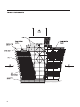
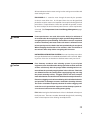
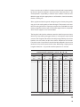
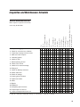
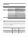
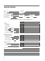
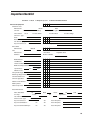
/ Marley Class 600 Cooling Tower /
User Manual 92-1317C
Tower Schematic
2
Contents
General...........................................................................................................................4
Before Start-up.............................................................................................................4
Initial Starting Procedure............................................................................................5
Routine Starting Procedure.......................................................................................6
Operation.......................................................................................................................6
Temperature Control and Energy Management....................................................9
Maintenance...............................................................................................................10
Cleaning......................................................................................................................12
Water Treatment........................................................................................................13
Seasonal Shutdown Instructions.......................................................................... 17
Spare Parts................................................................................................................18
Accessories................................................................................................................18
Inspection and Maintenance Schedule................................................................19
Troubleshooting.........................................................................................................20
Safety...........................................................................................................................21
Inspection Checklist.................................................................................................22
The following defined terms are used throughout this manual to
bring attention to the presence of hazards of various risk levels, or
to important information concerning the life of the product.
Warning
Indicates presence of a hazard which can cause severe personal
injury, death or substantial property damage if ignored.
Caution
Indicates presence of a hazard which will or can cause personal
injury or property damage if ignored.
Note
Indicates special instructions on installation, operation or maintenance which are important but not related to personal injury
hazards.
3
General
A cooling tower, like any heat exchanger, exchanges all heat imposed upon
it from one fluid to another fluid. For a cooling tower, heat from the water is
put into the air. The plant process replenishes the heat to the water, typically
at another heat exchanger such as a condenser. A cooling tower differs from
many heat exchangers in that heat is transferred in two forms — sensible and
latent heat. As heat is transferred from the water, the air temperature increases
(sensible) and the air's water content, or humidity, also increases (latent). As
the heat load, inlet air wet-bulb temperature, or airflow on a cooling tower
changes, the cooling tower will respond by finding a new equilibrium with the
process. The cooling tower will still dissipate all the heat from the process,
but at new water temperatures.
The cooling tower cold water temperature is the supply water temperature
to the condenser, and changes in the cold water temperature usually affect
efficiency of the plant output. Although the reduced cold water temperatures
that result from maximum fan power utilization are usually beneficial to plant
output, the amount of fan power affects the cost of running the cooling tower.
As these variables interact on a cooling tower, the operator must find the
proper trade-off between these opposing forces.
These instructions will assist in obtaining efficient, long life from Marley cooling
equipment. Direct questions concerning tower operation and maintenance
to your Marley sales representative. Always include your tower serial number
when writing for information or ordering parts. Look for this number on the
nameplate on the tower endwall access door.
Before Start-up
Caution
SAFETY—Temporary safety barricades should be placed around
any exposed openings in the operating (or non-operating) tower,
safety harnesses should be worn by personnel where appropriate,
and other safety precautions should be taken in compliance with
OSHA regulations and standards.
CLEANING—Remove any dirt and trash which has accumulated in the hot
water distribution basins. Clean any nozzles that are clogged. Remove any
sediment from the cold water basin, sump and screens. Use a water hose
to flush cold water basins. If you are restarting or recommissioning a
previously used tower, see Warning note on page 12.
4
OPERATE WATER SYSTEM—Complete steps 1 thru 4 under Initial Starting Procedure below. Circulate water over the tower continuously for several
days before starting the mechanical equipment and putting the tower into
continuous operation.
Note
Do not circulate water over the tower in freezing weather without a
heat load. (See caution, page 6.)
Initial Starting Procedure
1–Fill the cold water basin and circulating water system to a level 1/2"
(13 mm) below the overflow.
2–Completely open all hot water flow control valves.
3–Prime and start the circulating water pumps one at a time. Increase the
flow of circulating water gradually to design water rate to avoid surges or
water hammer which could damage the distribution piping.
4–When flow has stabilized at or near the design rate, adjust water makeup
to maintain the level that the water has pumped down to in the cold water
basin. See Cold Water Collecting Basin on page 8. This should coincide
reasonably with the recommended operating water level indicated on the
Marley project drawings.
5–Adjust flow control valves to equalize the hot water depth in the distribution basins. Adjust deepest water level basins first. Lock valves in desired
position with valve locking bar.
6–Start the fan. After 30 minutes operating time to permit Geareducer oil to
come up to operating temperature, check motor load with watt meter, or
take operating volt and ampere readings and calculate motor HP. Refer to
Marley Fan User Manual for instructions.
Caution
If it is necessary to pitch fans to pull correct contract horsepower,
measure results when circulating design water rate at design hot
water temperature. HP will change with air density. Lock out all
electrical service before entering fan area.
5
Routine Starting Procedure
After periods of routine shutdown, the following restarting procedure should
be followed:
1–Start the circulating water pump(s). Increase the flow of circulating water
gradually to design water rate to avoid surges or water hammer which could
damage the distribution piping.
Caution
Circulating cold water over a tower in freezing weather will cause
ice to form — which may cause damage to the fill system. Water
should be bypassed until the heat load causes its temperature to
rise above 70°F (21°C), at which time it may be directed over the
tower. Also, towers must not be operated with reduced water rate
and/or no heat load during freezing weather. If a bypass is used, do
not modulate. Bypass design must be reviewed by SPX.
2–Start the fan(s). On multicell towers, only as many fans should be started
as are needed to produce the desired cold water temperature. If the tower
is equipped with two-speed motors, fans may be progressively started at
half speed, increasing to full speed as necessary to maintain the desired
cold water temperature. See Temperature Control and Energy Management, pages 9 and 10.
Operation
TOWER PERFORMANCE—Keep the tower clean and the water distribution
uniform to obtain continued maximum cooling capacity. (See Warning note,
page 12.) Do not allow excessive deposits of scale or algae to build up on the
fill or eliminators. Keep the metering orifices free of debris to assure correct
distribution and cooling of water.
The capacity of a tower to cool water to a given cold water temperature varies
with the wet-bulb temperature and the heat load on the tower. As the wet-bulb
temperature drops, the cold water temperature also drops. However, the cold
water temperature does not drop as much as the wet-bulb temperature. Wetbulb temperature is the temperature indicated by the wet-bulb thermometer
of a psychrometer.
A tower does not control the heat load. For a given heat load, the quantity of
water circulated determines the cooling range. The hot and cold water temperatures increase with higher heat loads. Cooling range is the temperature
6
difference between the hot water coming into the cooling tower and the cold
water leaving the tower.
FAN DRIVE—Air is caused to move through the tower by the operation
of electric motor-driven fans. At full speed, these fans are designed (and
pitched) to move the amount of air required to accomplish the design thermal
performance. Proper utilization of these fans provides the operator a means
by which to adjust the level of thermal performance to suit the requirements
of the load. (See Temperature Control and Energy Management, pages
9 and 10.)
Caution
If two-speed motors are used, allow a time delay of a minimum of
20 seconds after de-energizing the high speed winding and before
energizing the low speed winding. Tremendous stresses are placed
on driven machinery and motor unless the motor is allowed to slow
to low speed rpm or less before the low speed winding is energized.
When changing the direction of fan rotation, allow a minimum of
two minutes time delay before energizing the fan motor.
HOT WATER DISTRIBUTION SYSTEM—Hot water from the process flows
into open distribution basins situated above the banks of fill in each cell. Metering orifices in the floor of these basins distribute water evenly over the fill.
Caution
If an Amertap condenser tube cleaning system is part of plant
equipment, care should be taken during operation to back-wash the
strainer section only after the sponge rubber cleaning balls are removed from the system by trapping them in the collector. If the balls
are allowed to enter the cooling tower supply piping, they can clog
the plastic metering orifices. Clogged orifices will cause unequal
water distribution over the fill which will affect thermal performance.
Extensive clogging can lead to overflowing of the distribution basins
and possible ice damage to towers installed in freezing climates.
The basins should be frequently checked for orifice clogging until
such time as the operational sequence of the Amertap system assures that no balls enter the cooling tower piping.
FILL—Water leaving the distribution basin orifices is distributed uniformly over
the fill plan area. The water cascades downward through the fill, maximizing
water surface exposure to the air being moved by the fans.
➠
7
DRIFT ELIMINATORS—Air leaving the fill passes through a bank of drift
eliminators blanketing the entire height of the fill. The purpose of these drift
eliminators is to minimize the amount of water that is caused to exit the tower
by the velocity of the moving airstream.
COLD WATER COLLECTING BASIN—Water leaving the fill falls into the
cold water basin that forms the base of the tower. The normal water depth in
a wood basin is 5 to 8 inches (127 to 203 mm), while in a concrete basin, the
normal water level is 9 to 15 inches (229 to 381 mm) below the curb. Adjust
the make-up water supply to maintain this water level. Maintain sufficient
water depth to prevent cavitation.
WINTER OPERATION—During periods of low temperature operation, 35° to
40°F (2°to 4°C) or below, ice will form on the relatively dry parts of the tower
that are in contact with the incoming air. Primarily, this includes the louvers
and adjacent structural framing.
Ice forming characteristics on any given tower will vary, depending on velocity and direction of wind, circulating water rate and heat load. Excessive ice
formation may be controlled by regulating air and water flow through the tower
by one or more of the following procedures:
1–Shut the fan down. This reduces the cooling rate to a minimum and increases the quantity of warm water on the louvers to a maximum, Except
for extreme cold conditions or extended freezing conditions, this procedure
will normally control ice formation. For automatic operation, a timer switch
can be provided to shut the fan down for a few minutes each hour.
2–If the tower has two-speed motors, operate the fan at half speed forward.
This reduces the cooling rate (heat transfer) and increases the quantity of
warm water on the louvers.
3–Under extended extreme cold conditions, it may be necessary to operate
the fan in reverse. This forces warm air out through the louvers, melting any
accumulated ice. Reversal may be at either full or half speed, however, full
speed is recommended if adequate heat load is available. Reverse operation of the fan should only be used to control ice, not prevent it. Reverse
fan operation should not exceed 15 to 20 minutes. Usually much less time
than this is required to melt accumulated ice. (See Caution, page 7)
4–With no heat load on the circulating water, icing cannot be controlled effectively by air control during freezing weather. Towers must not be operated with reduced water rate and/or no heat load during freezing weather.
If a bypass directly into the cold water basin is used, all water must be
bypassed. Design of a bypass arrangement must include consideration of
water impact effect on tower components.
8
Caution
Reverse operation of fans for prolonged periods during subfreezing
weather can cause severe damage to fans and fan cylinders. Ice
can accumulate inside fan cylinders at fan blade plane of rotation
and fan blade tips will eventually strike this ring of ice, damaging
the fan blades or cylinder. Ice can also accumulate on fan blades
and be thrown off, damaging fan cylinder or blades. Reverse operation of fans with adjacent fans not operating increases probability
of icing. The low discharge velocity of moist air from fan cylinders
in which fans are not in operation can result in moisture-laden air
being pulled into the adjacent cylinder in which the fan is operating
in reverse, increasing this ice buildup. Therefore, fans each side of
the one operating in reverse must be operated in forward rotation
at full or half speed, or all fans must be operated in reverse. Allow
at least a 10 minute delay between reverse operation and forward
operation during subfreezing weather to permit ice to dissipate from
fan blades and fan cylinders. See Fan Drive Caution note on page
7 for fan speed change and reversing precautions.
Temperature Control and Energy Management
The wet bulb temperature of the ambient air varies significantly on a daily
basis, and considerably from season to season. As the wet bulb temperature
reduces, the tower becomes capable of producing colder and colder water — or
it becomes capable of producing a given cold water temperature at reduced
airflow through the tower. These characteristics are the “opposing forces”
referred to under General on page 4.
MAXIMIZING TOWER PERFORMANCE—If your process is one which
benefits from the coldest possible water; that is, if colder water allows you to
produce more product — or allows you to operate your system at significantly
lower cost, then continuous full speed operation of the fan(s) may be your
best mode of operation.
In this mode of operation, concern for the cold water temperature level would
be limited to the potential for the tower to form ice during freezing weather.
(See Caution page 6, and WINTER OPERATION pages 8 and 9) Although
the 70°F (21°C) cold water temperature indicated on page 6 is appropriate
for cold weather start-up and operation, acceptable temperatures during full
operation in spring, summer and fall may be appreciably lower, perhaps as low
as 50°F (10°C) or less. Refer to your performance curves for expected
tower cold water temperatures at varying flow rates, ranges, and wet
bulb temperatures.
➠
9
MINIMIZING TOWER ENERGY USE—Many processes gain no operating
or production benefits from water temperatures below a certain level, and for
many that level may be only 10°F to 15°F (5° to 8°C) below the design cold
water temperature. When a reducing ambient wet bulb permits the tower to
reach that target cold water temperature level, further reductions in the wet
bulb temperature permit manipulation of fan speeds or operation to maintain
that temperature level.
Single speed fans can be cycled on and off for cold water temperature control, with the steps of control depending upon the number of fan cells in the
tower. Two speed motors offer twice as many control steps — with the added
bonus that half speed (which produces half of the normal airflow through
the tower) requires less than 20% of the full speed power requirement. (If
your tower is equipped with a Marley Motor Control Center and/or
a Marley Smart System temperature controller, please refer to the
appropriate Owners Manuals.)
Caution
Excessive fan cycling may shorten the motor's expected service life.
On fans 20 feet (6 meter) diameter and smaller allow for 4 to 5 starts
per hour. On larger fans, 2 or 3 starts per hour may be the limit. On
speed motors each low speed start and each high speed start
two
count as one start.
Variable frequency drives, of course, provide the ultimate in both temperature control and energy management and can be easily retrofitted to your
system. Please discuss this with your Marley representative. (If your tower
is equipped with a Marley VFD drive, please refer to the appropriate
Owners Manual.)
Unit Maintenance
Well maintained equipment gives the best operating results and the least
maintenance cost. A regular inspection schedule is recommended to insure
effective, safe operation of the cooling tower. Use the schedule on page 19
to obtain continuously good performance with the least tower maintenance.
See Inspection Checklist, pages 22 and 23 in this manual. Keep a continuous
lubrication and maintenance record for each cooling tower. Conduct regular
inspection and repair of personnel safety items (items 19 and 20 in Table on
page 19). Maintaining a record of this is especially important. For a supply of
check list forms, contact your Marley sales representative.
10
HOT WATER DISTRIBUTION BASINS—Metering orifices in the floor of the
hot water basins may be cleaned without shutting down any part of the tower.
Remove dirt, algae, leaves, etc., which might get in these basins or orifices. The
metering orifices must be kept in place to assure proper water distribution.
Completely open and close flow control valves at least semi-annually to remove
any scale on the threads. Before operating valve, measure distance from valve
stem guide to operating handle to assist in resetting the valve to the original
operating position. Grease the stainless steel stem to prevent scale forming.
Lubricate the valves at least semiannually with a lithium base NLGI No. 2
consistency grease. More frequent relubrication of valves and valve stems
may be dictated by circulating water conditions.
COLD WATER COLLECTING BASIN—Inspect collecting basin occasionally for cracks, leaks, and spalling and repair if necessary. Maintain a positive
Langelier index in your circulating water. (See Water Treatment, page 15.)
Minor leaks may appear in wood basins when starting with a dry basin but
these generally disappear after the wood becomes soaked. Keep cold water
outlets clean and free of debris. Makeup and circulating water controls must
operate freely and maintain the desired water quantity in the system.
TOWER FRAMEWORK—Keep framework bolts tight. Pay particular attention to bolts in the mechanical equipment supports. Do not pull washers into
the wood.
DRIVE SHAFT—Check drive shaft alignment and condition of couplings every
six months. See the Drive Shaft Service Manual for correcting misalignment, balancing or replacing parts.
ELECTRIC MOTOR—Lubricate and maintain each electric motor in accordance
with the manufacturer’s instructions. If repair work is necessary, contact the
nearest representative of the motor manufacturer. See Warranty Section of
Marley Service Manual on Electric Motors.
FAN—Inspect fan blade surfaces every six months. For detailed maintenance
information, refer to Marley Fan Service Manual.
GEAREDUCER—Make weekly and monthly oil checks. Refer to the Geareducer User Manual for detailed maintenance instructions.
PAINTING—Periodically clean and, if necessary, recoat any chipped or damaged paint to prevent corrosion.
➠
11
COOLING TOWER WOOD DETERIORATION—Cooling tower wood is
pressure treated to help prevent decay. However, after several years of service,
some members may develop decay. Routine inspections should be made to
assure that decay is discovered before it is heavily advanced.
Decay is commonly of two very general types, soft rot and internal rot. Soft
rot is easier to detect because it is almost always on the surface of wood
members. It makes the surface soft and weak and, in its more advanced
stages, the decayed wood can be easily removed. This type of rot occurs
primarily in the flooded areas of the tower. Internal rot, as the name implies,
occurs inside the wood members. For this reason it is more difficult to detect
than is soft rot. Internal rot is most commonly found in the heavier members
in the plenum areas of the tower. One of the best methods of inspection for
internal rot is “sounding” with hammer blows. Members which have internal rot
sound “dead” while non-rotted members have a “ring” or “live” sound. Areas
which sound “dead” can be probed with a screwdriver or other pointed tool
to verify the presence of internal rot. The strength of a member with soft rot
is not seriously affected. However, if internal rot is discovered, the infected
members should be replaced.
SPX has personnel on its staff experienced in all aspects of wood deterioration
and preservative treatment. In addition, several Marley publications are available which give detailed information on the subject of wood deterioration and
treatment. Contact the nearest Marley sales representative for more information
about wood inspection services and for copies of the publications.
Cooling Tower Cleaning
Warning
Any evaporative-type cooling tower must be thoroughly cleaned on
a regular basis to minimize the growth of bacteria, including
Legionella Pneumophilla, to avoid the risk of sickness or death. Service personnel must wear proper personal protective equipment.
Do NOT attempt any service unless the fan motor is locked out.
Operators of evaporative cooling equipment, such as water cooling towers,
should follow maintenance programs which will reduce to an absolute minimum
the opportunity for bacteriological contamination. Public Health Service officials
have recommended that “good housekeeping” procedures be followed, such
as: regular inspections for concentrations of dirt, scale, and algae; periodic
flushing and cleaning; and the following of a complete water treatment program
including biocidal treatment.
12
Visual inspection should take place at least once a week during the operating
season. Periodic flushing and cleaning should be done at least twice a year.
Nozzles, louvers, drift eliminators, and easily accessible fill surfaces should
be flushed by use of a moderate-pressure water nozzle, being careful not to
cause physical damage. A reliable water treatment program should be installed
and maintained.
Water Treatment
BLOWDOWN–Blowdown, or bleed-off, is the continuous removal of a portion of the water from the circulating system. It is used to prevent dissolved
solids from concentrating to the point where they will form scale. The amount
of blowdown required depends upon the cooling range (design hot water
temperature minus design cold water temperature) and the composition of
the makeup water (water added to the system to compensate for losses by
blowdown, evaporation and drift). The following table shows the minimum
amount of blowdown (percent of flow) required to maintain different concentrations with various cooling ranges:
Cooling Range
Number of Concentrations
1.5X
2.0X
2.5X
3.0X
4.0X
5.0X
6.0X
5ºF (2.78ºC)
.78
.38
.25
.18
.11
.08
.06
10ºF (5.56ºC)
1.58
.78
.51
.38
.25
.18
.14
15ºF (8.33ºC)
2.38
1.18
.78
.58
.38
.28
.22
20ºF (11.11ºC)
3.18
1.58
1.05
.78
.51
.38
.30
25ºF (13.89ºC)
3.98
1.98
1.32
.98
.64
.48
.38
Multipliers are based on drift of 0.02% of the circulating water rate.
EXAMPLE: 7000 GPM (441.7 L/s) circulating rate, 18°F (10°C) cooling
range. To maintain 4 concentrations, the required blowdown is 0.458% or
.00458 times 7000 GPM (441.7 L/s) which is 32.1 GPM (2.02 L/s).
If tower is operated at 4 concentrations, circulating water will contain four
times as much dissolved solid as the makeup water, assuming none of the
solids form scale or are otherwise removed from the system.
➠
13
Note
The use of corrosion and scale inhibitors is strongly recommended.
CHEMICAL TREATMENT–In some cases chemical treatment of the circulating water is not required if adequate blowdown is maintained. In most
cases, however, chemical treatment is required to prevent scale formation and
corrosion. Sulfuric acid or one of the polyphosphates is most generally used
to control calcium carbonate scale. Various proprietary materials containing
phosphates or other compounds are available for corrosion control. When
water treatment chemicals are required, the services of reliable water treating
companies should be obtained.
Note
Preferred Cooling Tower Water Condition Limits
For Standard Construction Materials
pH
Maximum Water Temperature
Langelier Saturation Index
M-Alkalinity
Silica
Iron
Manganese
Oil and Grease
-
Sulfides Ammonia Chlorine Organic Solvents Total Dissolved Solids -
Cations:
Anions:
Suspended Solids:
14
Calcium
Magnesium
Sodium
6.5 to 9.0
120ºF (48.9ºC)
0.0 to 1.0
100 to 500 ppm as CaCO3
150 ppm as SiO2
3 ppm
0.1 ppm
10 ppm for splash-filled towers.
None allowed for film-filled towers.
1 ppm
50 ppm if copper alloys are presents.
1 ppm free residual intermittently (shock),
or 0.4 ppm continuously.
None allowed.
Over 5000 ppm can affect thermal performance.
- 800 ppm as CaCO3
- Depends of pH and Silica level.
- No limit.
Chlorides - 750 ppm as NaCl, 455 ppm as ClSulfates - 800 ppm as CaCO3
Nitrates - 300 ppm (nutrient for bacteria)
Splash-Type Fill - No specific limit.
Unless unusual water conditions have been anticipated and compensated for
by the use of premium materials in the construction of the tower, then it is the
owner/operator's responsibility to maintain water conditions within the limits
tabled on page 14 by the appropriate use of blowdown, chemical treatment,
filtration, cleaning, etc.
Slime, a gelatinous bacteria growth, and algae, a green or brown plant growth,
may grow in the cooling tower or heat exchangers. Their presence can interfere with cooling efficiencies. Proprietary compounds are available from water
treating companies for the control of slime and/or algae; however, compounds
which contain copper are not recommended.
The Langelier index (calcium carbonate saturation index) has proven to be an
effective tool in predicting the aggressiveness of cooling tower water toward
concrete. The Langelier index relates the methyl orange alkalinity; the calcium
hardness; the total solids; the pH value; and the temperature of the water.
From these values it is possible to calculate the index and predict the corrosive
tendencies of the tower water toward concrete. Maintaining a slightly positive
Langelier index (0.0 – 1.0) provides excellent protection of concrete.
Data For Rapid Calculation of Saturation Index
Saturation Index = pH(actual) - (9.3 + A + B) + (C + D)
A
B
C
D
Total
Solids
ppm
Value
to
Apply
Water
Temp.
(ºF)
Value
to
Apply
Calcium
Hardness
ppm
Value
to
Apply
M.O.
Alkalinity
ppm
Value
to
Apply
50 - 300
400 - 1000
0.1
0.2
32 - 34
36 - 42
44 - 48
50 - 56
58 - 62
64 - 70
72 - 80
82 - 88
90 - 98
100 - 110
112 - 122
124 - 132
134 - 146
148 - 160
162 - 178
2.6
2.5
2.4
2.3
2.2
2.1
2.0
1.9
1.8
1.7
1.6
1.5
1.4
1.3
1.2
10 - 11
12 - 13
14 - 17
18 - 22
23 - 27
28 - 34
35 - 43
44 - 55
56 - 69
70 - 87
88 - 110
111 - 138
139 - 174
175 - 220
230 - 270
280 - 340
350 - 430
440 - 550
560 - 690
700 - 870
880 - 1000
0.6
0.7
0.8
0.9
1.0
1.1
1.2
1.3
1.4
1.5
1.6
1.7
1.8
1.9
2.0
2.1
2.2
2.3
2.4
2.5
2.6
10 - 11
12 - 13
14 - 17
18 - 22
23 - 27
28 - 34
35 - 43
44 - 55
56 - 69
70 - 87
88 - 110
111 - 138
139 - 174
175 - 220
230 - 270
280 - 340
350 - 430
440 - 550
560 - 690
700 - 870
880 - 1000
1.0
1.1
1.2
1.3
1.4
1.5
1.6
1.7
1.8
1.9
2.0
2.1
2.2
2.3
2.4
2.5
2.6
2.7
2.8
2.9
3.0
Based on Langelier formulas, Larson-Buswell residue,
temperature adjustments and arranged by Eskel Nordell.
➠
15
FOAMING–Heavy foaming sometimes occurs when a new tower is put into
operation. This type of foaming generally subsides after a relatively short period of operation. Persistent foaming can be caused by the concentrations of
certain combinations of dissolved solids or by contamination of the circulating
water with foam-causing compounds. This type of foaming can sometimes be
minimized by increasing the blowdown, but in some cases foam depressant
chemicals must be added to the system. Foam depressants are available from
a number of chemical companies.
WATER DISCOLORATION—Woods contain some water-soluble substances
and these commonly discolor the circulating water on a new tower. This discoloration is not harmful to any of the components in the system and can be
ignored. However, a combination of foaming and discolored water can result in
staining of adjacent structures if foam is picked up by air being pulled through
the tower and discharged out the fan cylinders. Avoid operation of fans until
the foaming is controlled.
16
Seasonal Shutdown Instructions
TOWER–Drain all tower piping.
During shutdown, clean the tower and make any necessary repairs. Apply
protective coating as required to all metal parts. Particular attention should be
given to mechanical equipment supports, drive shaft and drive shaft guards.
Visually inspect for concrete deterioration.
Warning
See Warning note on page 12 regarding tower cleaning.
MECHANICAL EQUIPMENT
Shutdown for less than 3 months.
Each month, drain water condensate from the lowest point of the Geareducer
and its oil system. Check oil level and add oil if necessary. Operate Geareducer
to recoat all interior surfaces with oil. Before start-up, drain water condensate
and check oil level. Add oil if necessary.
Refer to Geareducer Service Manual for maintenance and lubrication
instructions.
Shutdown for 3 months or longer.
If the motors have space heaters, operate mechanical equipment one hour
each month. Space heaters should be energized anytime motor is not operating. If the motors do not have space heaters, operate mechanical equipment
one hour each week. At start-up, operate mechanical equipment one hour or
until oil is warm, then shut the equipment down. Drain the oil and refill with
new oil. Refer to Geareducer User Manual for instruction on changing oil.
Refer to Marley Downtime Instruction Manual for downtime of 6 months
or longer.
Electric Motors
Caution
Do not start motor without determining that there will be no interference with free rotation of the fan drive. Refer to Marley Electric
Motor Service Manual.
If shutdown period is longer than seasonal, contact your Marley sales representative for additional information.
17
Spare Parts
SPX manufactures and maintains a stock of common replacement parts for
all cooling tower mechanical equipment. Shipment of these parts are normally
made within ten days after an order is received. If emergency service is necessary, contact the local Marley sales representative for assistance.
To prevent prolonged shutdown periods in case of damage to the mechanical
equipment, it is suggested that the following parts be carried in the owner’s
stock:
• One fan assembly.
• One Geareducer assembly.
• One driveshaft assembly.
• One motor.
Be sure to furnish the tower serial number when ordering parts.
Accessories
Marley accessories are designed for improved maintenance access, safety,
component handling, and the general customizing of the tower to suit your
process. These accessories include stairways, walkways (external and internal),
mechanical equipment removal systems, derricks, davits, hot water basin covers
(for algae suppression), motor control centers as well as variable frequency
drives (page 10), and other retrofittable control devices.
Please discuss your needs with your Marley representative.
18
Inspection and Maintenance Schedule
1. Inspect for clogging
D D D D
3. Inspect keys, keyways and set screws
S S S S
4. Make sure vents are open
W
Stairs, Ladders, Walkway, Doors, Handrails
Fan Cylinder
Casing and Louvers
Structural Members
Control Valves
Suction Screen
Float Valve
Hot Water Basin
Cold Water Basin
Fill
M M
2. Check for unusual noise or vibration
W
S
5. Lubricate (grease)
R
S
6. Check oil seals
7. Check operating oil level
M
D
8. Check static oil level
M
9. Check oil for water and sludge
M
10. Change oil
S
11. Check fan blade tip clearance
Drift Eliminators
Geareducer
Motor
Drive Shaft and Guards
Fan
More frequent inspection and maintenance may be desirable
Davits, Derricks, Hoists
General Recommendations
S
12. Check water level
D D
13. Check for leakage
W
S S S
14. Inspect general condition
S S S S Y S Y S Y S S S Y S S S
15. Tighten loose bolts
S S S S
16. Clean
R R R R R R
17. Repaint
R R R R
18. Rebalance
R
Y R
S R R R R
R
19. Completely open and close
20. Inspect/repair for safe use
21. Inspect and repair before each use
S
S
Y
Y
S
R
D – daily; W – weekly; M – monthly; Q – quarterly; S – semi-annually; Y – yearly; R – as required
19
Troubleshooting
Trouble
Cause
Remedy
Motor Will Not Start
Power not available at motor terminals
• Check power at starter. Correct any bad connections
between the control apparatus and the motor.
• Check starter contacts and control circuit. Reset overloads,
close contacts, reset tripped switches or replace failed control
switches.
• If power is not on all leads at starter, make sure overload
and short circuit devices are in proper condition.
Check motor and control connections against wiring diagrams.
Wrong connections
Low voltage
Open circuit in motor winding
Motor or fan drive stuck
Rotor defectve
Unusual Motor Noise
Motor Runs Hot
Motor running single-phase
Motor leads connected incorrectly
Ball bearings
Check lubrication. Replace bad bearings.
Electrical unbalance
Air gap not uniform
Check voltages and currents of all three lines. Correct if
required.
Check and correct bracket fits or bearing.
Rotor unbalance
Rebalance.
Cooling fan hitting guard
Reinstall or replace fan.
Wrong voltage or unbalanced voltage
Check voltage and current of all three lines against nameplate
values.
Check fan blade pitch. See Fan User Manual. Check for
drag in fan drive train as from damaged bearings.
Check nameplate against power supply. Check RPM of motor
and gear ratio.
Remove grease reliefs. Run motor up to speed to purge
excessive grease.
If not poor machining, replace worn bearing.
Wrong motor RPM
Bearings overgreased
Rotor rubs stator bore
Wrong lubricant in bearings
Winding fault
Change to proper lubricant. See motor manufacturer's
instructions.
Stop motor and attempt to start it. Motor will not start if singlephased. Check wiring, controls, and motor.
Clean motor and check ventilation openings. Allow ample
ventilation around motor.
Check with Ohmmeter.
Bent motor shaft
Straighten or replace shaft.
Insufficient grease
Remove plugs and regrease bearings.
Deterioration of grease, or foreign
material in grease
Bearings damaged
Flush bearings and relubricate.
Incorrect fan blade pitch
See Fan User Manual for blade pitching instructions.
Voltage too low at motor terminals
because of line drop
Check transformer and setting of taps. Use higher voltage on
transformer terminals or reduce loads. Increase wire size or
reduce inertia.
Look for cracks near the rings. A new rotor may be required.
Have motor service person check motor.
One phase open
Poor ventilation
Broken Rotor bars
20
Disconnect motor from load and check motor and Geareducer
for cause of problem.
Look for broken bars or rings.
Stop motor and attempt to start it. Motor will not start if singlephased. Check wiring, controls, and motor.
Check motor connections against wiring diagram on motor.
Overload
Motor Does Not Come Up
To Speed
Check nameplate voltage against power supply. Check
voltage at motor terminals.
Check stator windings for open circuits.
Replace bearings.
Troubleshooting
Trouble
Cause
Remedy
Wrong Rotation (Motor)
Wrong sequence of phases
Switch any two of the three motor leads.
Geareducer Noise
Geareducer bearings
Loose fan hub cover
If new, see if noise disappears after one week of operation.
Drain, flush, and refill Geareducer. See Geareducer Service
Manual. If still noisy, replace.
Correct tooth engagement. Replace badly worn gears.
Replace gears with imperfect tooth spacing or form.
Tighten all bolts and cap screws on all mechanical equipment
and supports.
Make sure motor and Geareducer shafts are in proper
alignment and "match marks" properly matched. Repair or
replace worn couplings. Rebalance drive shaft by adding or
removing weights from balancing cap screws. See Drive
Shaft Service Manual.
Make certain all blades are as far from center of fan as safety
devices permit. All blades must be pitched the same. See
Fan Service Manual. Clean off deposit build-up on blades.
Check fan and pinion shaft endplay. Replace bearings as
necessary.
Disconnect load and operate motor. If motor still vibrates,
rebalance rotor.
Check fan and pinion shaft with dial indicator. Replace if
necessary.
Tighten hub cover fasteners.
Blade rubbing inside of fan cylinder
Adjust cylinder to provide blade tip clearance.
Loose bolts in blade clamps
Check and tighten if necessary.
Gears
Unusual Fan Drive
Vibration
Loose bolts and cap screws
Unbalanced drive shaft or worn
couplings
Fan
Worn Geareducer bearings
Unbalanced motor
Bent Geareducer shaft
Fan Noise
Safety
The tower has been designed to provide a safe working environment while either operating or shut down. The ultimate
responsibility for safety rests with the Operator and Owner. When flow to the tower is shut off or when portions of the
tower require maintenance, temporary safety barricades may be required around openings. Other safety precautions
such as safety harnesses should be utilized where appropriate for compliance with OSHA regulations and standards
and good safety practices. See Warning, page 12.
Routine periodic maintenance must be performed on all personnel access and material handling accessories in accordance with the following schedule:
Ladders, Stairways,
Walkways, Handrails, Covers,
Decks, and
Access Doors
Davits, Derricks, and Hoists
Inspect for General Condition
Semi-annually
Semi-annually
Repair for Safe Use
As Required
As Required
21
Inspection Checklist
Date Inspected
Inspected By
Owner
Location
Owner's Tower Designation
Tower Manufacturer
Model No.
Process Served by Tower
Operation:
Design Conditions
GPM
HW
°F
Serial No.
Continuous
Intermittent
CW
°F
WB
Number of Fan Cells
Condition: 1—Good
2—Keep an eye on it
1 2 3
Structure
Casing Material
Structural Material
Fan Deck Material
Stairway?
Material
Ladder?
Material
Handrails?
Material
Interior Walkway?
Material
Cold Water Basin Material
Water Distribution System
Distribution Basin Material
Inlet Pipe Material
Inlet Manifold Material
Flow Control Valves?
Nozzles — Orifice Diameter
Size
"
"
Heat Transfer System
Fill
Drift Eliminators
Louvers
Use this space to list specific items needing attention:
22
3—Needs immediate attention
Comments
Seasonal
°F
Inspection Checklist
Condition: 1—Good
2—Keep an eye on it
Mechanical Equipment
3—Needs immediate attention
1 2 3
Comments
Gear Drive Units
Manufacturer
Oil Level:
Model
Full
Oil Condition:
Ratio
Add Immediately
Good
Low, check again soon
Contains Water
Contains Metal
Contains Sludge
Oil Used — Type
Seals
Backlash
Fan Shaft Endplay
Any Unusual Noises?
No
Yes
Action Required:
Drive Shafts
Manufacturer
Material
Fans
Manufacturer
Fixed Pitch
Diameter
Adjustable Pitch
Number of Blades
Blade Material
Hub Material
Hub Cover Material
Blade Assembly Hardware
Tip Clearance
"min.
"max.
Vibration Level
Fan Cylinder Height
Mech.Eqpt. Support Mat'l
Oil Fill and Drain Lines
Oil Level Sight Glass
Vibration Limit Switches
Makeup Valves
Other Components
Motor Manufacturer
Name Plate Data:
F.L. Amps
hp
RPM
Frame
Phase
SF
Hz
Volts
Special Info.
Last Lubrication — Date
Grease Used — Type
Any Unusual Noise?
No
Yes
Action Required
Any Unusual Vibration?
No
Yes
Action Required
Any Unusual Heat Build-up?
No
Yes
Action Required
23
7401 WEST 129 STREET | OVERLAND PARK, KANSAS 66213 UNITED STATES | 913 664 7400 | [email protected] | spxcooling.com
In the interest of technological progress, all products are subject to design and/or material change without notice.
©2009 SPX Cooling Technologies, Inc. | Printed in USA
Manual 92-1317C