1
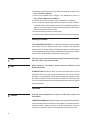
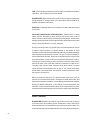
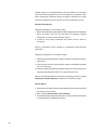
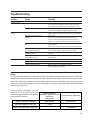
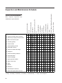
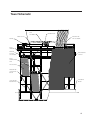
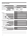
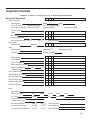
MatrixMultiflow
Owners Manual
R
Manual 93-1289
1
Contents
Before Start-up .............................................................................. page 3
Starting Procedure ......................................................................... page 4
Operation ....................................................................................... page 4
Tower Maintenance ....................................................................... page 6
Water Treatment ............................................................................ page 8
Spare Parts .................................................................................. page 11
Seasonal Shutdown Instructions .................................................. page 11
Cooling Tower Cleaning ............................................................... page 13
Troubleshooting ........................................................................... page 14
Safety .......................................................................................... page 15
Inspection and Maintenance ........................................................ page 16
Tower Schematic ......................................................................... page 17
Inspection Checklist ..................................................................... page 18
The following defined terms are used throughout this manual to bring
attention to the presence of hazards of various risk levels, or to
important information concerning the life of the product.
▲ Warning
Indicates presence of a hazard which can cause severe personal injury,
death or substantial property damage if ignored.
▲ Caution
Indicates presence of a hazard which will or can cause personal injury
or property damage if ignored.
▲ Note
Indicates special instructions on installation, operation or maintenance
which are important but not related to personal injury hazards.
▲ Note
2
These instructions assist in obtaining efficient, long life from Marley
cooling equipment. Direct questions concerning cooling tower operation
and maintenance to your Marley sales office or representative. Always
include your tower serial number when writing for information or
ordering parts. Look for this number on the nameplate on the access
door.
Before Start-up
CLEANING–Remove any dirt and trash which has accumulated in the cold
water basin. Clean any nozzles that are clogged. Remove any sediment from
the cold water collection basin, sump, and screens. Use a water hose to flush
cold water collection basins.
OPERATE WATER SYSTEM–Start the circulating water pumps. Increase
the flow of circulating water gradually to match design water flow rate.
Circulate water over the cooling tower continuously for several days before
starting the mechanical equipment and placing the cooling tower into continuous
operation.
▲ Note
When starting in cold weather, follow procedures outlined in Cold
Weather Operation on page 5.
INSPECTION–It is imperative that all operating assemblies be inspected
before they are placed in operation. The following is a list of components to be
checked before starting the tower:
1–Check drive shaft alignment. Realign if necessary. See Marley Drive Shaft
Service Manual.
2– Check tightness of bolts that attach mechanical equipment support to the
tower framing. Check tightness of bolts in fan cylinder joints and fan cylinder
anchorage. Do not pull washers into the wood.
3–Check tightness of bolts at diagonals and columns, and at girts and columns
in the area between fan and cold water basin.
4–Check tightness of the following bolted joints in the fan and drive assemblies:
a–Fan hub clamp bolts. See Marley Fan Service Manual for correct
torque setting.
b–Fan hub cover bolts. Where applicable.
c–Geareducer® and motor mounting bolts.
d—Drive shaft coupling and guard bolts.
5–Check Geareducer oil for sludge or water by draining off and testing a
sample as outlined in the Marley Geareducer Service Manual. Check
Geareducer oil level at “oil level” mark on the side of the case. Add oil as
required. The oil level placard must be adjusted so that its “full” mark is at
the same elevation as the “full” mark on the side of the Geareducer case.
Check oil lines to be sure there are no leaks and all joints are tight. See
Geareducer Service Manual for oil filling procedure and list of recommended
lubricants.
—continues
3
6–Rotate fan by hand to be sure of free rotation and ample tip clearance. See
Marley Fan Service Manual.
7–Check motor insulation with a “Megger”. See Maintenance Section of
Marley Electric Motor Service Manual.
8–Lubricate the motor according to motor manufacturer’s instructions.
9–Test run each fan separately for a short time. Check for excessive vibration
or unusual noise. If either is present, refer to the Troubleshooting section on
pages 14 & 15 of this manual. Fan must rotate clockwise when viewed from
above. Recheck Geareducer oil level.
10–Check functioning of make-up water supply.
11–Make sure the blowdown or bleed-off will carry the proper amount of water.
Starting Procedure
FILL THE WATER SYSTEM–Fill the cold water collection basin and circulating
water system until the operating water level is reached. See Operation
Section, below. Prime and start the circulating water pumps. Increase the flow
of circulating water gradually to design water flow rate to avoid surges of water
hammer which could damage the distribution system piping.
▲ Note
Clean the sump screens several times during the first weeks of operation.
After this, check sump screens weekly.
▲ Note
When starting in cold weather, follow procedures outlined in Cold
Weather Operation.
STARTING FAN–Start the fan. After 30 minutes of operating time to permit
Geareducer oil to come up to operating temperature, check motor load with
watt meter, or take operating volt and ampere readings and calculate motor
HP. Refer to Marley Fan Service Manual for instructions. Pitch fans to pull
correct contract horsepower when circulating design water rate at design hot
water temperature.
Operation
▲ Caution
Entering water temperature in excess of 125°F may result in fill
deformation.
TOWER PERFORMANCE–Keep the cooling tower clean and water distribution
uniform to obtain continued maximum cooling capacity. Do not allow excessive
deposits of scale or algae to build up on the fill and eliminators. Keep the
nozzles free of debris to assure correct distribution and cooling of water.
4
The capacity of a cooling tower to cool water to a given cold water temperature
varies with the wet-bulb temperature and the heat load applied to the cooling
tower. As the wet-bulb temperature drops, the cold water temperature also
drops. However, the cold water temperature does not drop linearly with the
wet-bulb temperature.
A cooling tower will not control heat load. The flow rate of water circulated
through the cooling tower will determine the temperature range of cooling in
conjunction with a given heat load. The hot water and cold water temperatures
will increase with higher heat loads and/or high flow rates.
HOT WATER DISTRIBUTION SYSTEM–Keep nozzles clean and in place in
distribution basins. Adjust water flow to give the same depth in the distribution
basins of all cells. Design water depth varies from 3" to 8" (7.6 cm to 20.3 cm)
depending upon design circulating water rate. If a major change in the quantity
of water to be circulated over the tower is made, replace the removable
nozzles with higher capacity nozzles to maintain the proper water level.
COLD WATER COLLECTION BASIN–A suitable depth must be maintained
to keep the pumps from pulling air into the line. The amount of “make-up” water
required to keep the water in the collection basin at the required depth depends
upon the “evaporation loss” and “blowdown.” Low operating depths of the
water require air baffles under the fill to prevent air bypass. Maintain sufficient
water depth to prevent cavitation. Normal operating water depth in a concrete
basin is at the base of the bottom fill sheets. (Normally 1'-6" below the top of
the basin curb.)
FAN DRIVE–When using two-speed motors, allow a time delay of a minimum
of 20 seconds after de-energizing the high-speed winding and before energizing
the low-speed winding. Tremendous stresses are placed on driven machinery
and motors unless the motors are allowed to slow to low-speed RPM or less
before the low-speed winding is energized.
COLD WEATHER OPERATION–During operation in subfreezing weather,
the opportunity exists for ice to form in the colder regions of the tower. Your
primary concern is to prevent the formation of destructive ice on the cooling
tower fill. Your understanding of cold weather operation will be enhanced if you
read “Operating Cooling Towers in Freezing Weather” Marley Technical
Report #H-003.
—continues
5
Ice forming characteristics on any given cooling tower will vary, depending on
velocity and direction of wind, circulating water rate, and heat load. Excessive
ice formation may be controlled by regulating air and water flow through the
tower by one or more of the following procedures:
1. Shut the fan down. This reduces the cooling air rate to a minimum and
increases the quantity of warm water at the air inlet to a maximum. Except
for extreme cold conditions or extended freezing conditions, this procedure
will normally control ice formation.
2. When a cooling tower has two-speed motors, operate the fans at half speed
forward. This reduces the cooling air rate (heat transfer) and increases the
quantity of warm water at the air inlet.
3. With no heat load on the circulating water, icing cannot be controlled.
Towers must not be operated with reduced water rate and/or no heat load
during freezing weather. If a bypass directly into the cold water basin is
used, all water must be bypassed.
▲ Caution
Reverse operation of fans is not recommended .
See “Fan Drive” for fan speed change precautions.
INTERMITTENT OPERATION–When the unit is operated intermittently
during winter weather, it is necessary that the water be drained from the tower
piping to insure protection against freezing and possible rupture.
Tower Maintenance
Well-maintained equipment gives the best operating results and the least
maintenance cost. Marley recommends setting up a regular inspection
schedule to insure effective, safe operation of the cooling tower. Use the
schedule on page 16 to obtain continuously good performance with the least
tower maintenance. See Cooling Tower Inspection Check List in this manual,
pages 18 and 19. Keep a continuous lubrication and maintenance record for
each cooling tower.
HOT WATER DISTRIBUTION BASINS–Water distribution nozzles in the
floor of the hot water basins may be cleaned without shutting down any part
of the tower. Remove dirt, algae, leaves, etc., from the basins or nozzles.
6
▲ Caution
If an Amertap condenser tube cleaning system is part of plant equipment,
care should be taken during operation to back-wash the strainer section
only after the sponge rubber cleaning balls are removed from the system
by trapping them in the collector. If the balls are allowed to enter the
cooling tower supply piping, they can clog the plastic metering orifices.
Clogged orifices will cause unequal water distribution over the fill which
will affect thermal performance. Extensive clogging can lead to
overflowing of the distribution basins and possible ice damage to
towers installed in freezing climates. The basins should be frequently
checked for orifice clogging until such time as the operational sequence
of the Amertap system assures that no balls enter the cooling tower
piping.
HOT WATER DISTRIBUTION SYSTEM–Keep the circulating water and
distribution piping and splashboxes clean and free of dirt, algae, and scale.
Algae and scale may clog nozzles, eliminators, fill, and piping, and may collect
on the equipment served thus reducing its performance. See warning under
“Water Treatment” section on page 8.
Distribution basins can be reached from the fan deck level through access
hatches and permanently installed ladders. The lower level distribution basins
may have an optional interior walkway which would be accessed from the
tower stairway.
COLD WATER COLLECTION BASIN (supplied by others)–Inspect collection
basin occasionally for leaks and repair if necessary. Keep cold water outlets
clean and free of debris. Make-up and circulating water controls must operate
freely and maintain the desired water quantity in the system.
TOWER FRAMEWORK–Keep framework bolts tightened. Pay particular
attention to bolts in the mechanical equipment supports. Do not pull washers
into the wood.
DRIVE SHAFT–Check drive shaft alignment and condition of couplings every
six months. See the Drive Shaft Service Manual for correcting misalignment,
balancing, or replacing parts.
ELECTRIC MOTOR–Lubricate and maintain each electric motor in accordance
with the manufacturer’s instructions. If repair work is necessary, contact the
nearest representative of the motor manufacturer. See Warranty Section of
Marley Service Manual on Electric Motors.
—continues
7
FAN–Inspect fan blade surfaces every six months. For detailed maintenance
information, refer to Marley Fan Service Manual.
GEAREDUCER–Make weekly and monthly oil checks. Inspect internal parts
during seasonal oil change. Refer to the Geareducer Service Manual for
detailed maintenance instructions.
PAINTING–Periodically clean and, if necessary, recoat all metal parts subject
to corrosion.
COOLING TOWER WOOD DETERIORATION—Treated wood in cooling
towers could be damaged by decay anytime after the first year or two of
service. If decay is discovered and corrected in its early stages, serious wood
damage can be prevented. Routine inspections should be made to assure that
decay is discovered before it is heavily advanced.
Decay is commonly of two very general types, soft rot and internal rot. Soft rot
is easier to detect because it is almost always on the surface of wood
members. It makes the surface soft and weak and in its more advanced stages
the decayed wood can be easily removed. This type of rot occurs primarily in
the flooded areas of the tower. Internal rot, as the name implies, occurs inside
the wood members. For this reason it is more difficult to detect than is soft rot.
Internal rot is most commonly found in the heavier members in the plenum
areas of the tower. One of the best methods of inspection for internal rot is
“sounding” with hammer blows. Members which have internal rot sound
“dead” while non-rotted members have a “ring” or “live” sound. Areas which
sound “dead” can be probed with a screwdriver or other pointed tool to verify
the presence of internal rot.
Marley maintains a laboratory for detailed wood inspections and has
personnel on its staff experienced in all aspects of wood deterioration and
preservative treatment. In addition, several Marley publications are available
which give detailed information on the subject of wood deterioration and
treatment. Contact the nearest Marley sales office or representative for more
information about wood inspection services and for copies of the publications.
Water Treatment
BLOWDOWN–Blowdown, or bleed-off is the continuous removal of a portion
of the water from the circulating system. Blowdown is used to prevent the
dissolved solids from concentrating to the point where they will form scale. The
amount of blowdown required depends upon the cooling range (the difference
8
between the hot and cold water temperatures) and the composition of the
make-up water (water added to the system to compensate for losses by
blowdown, evaporation and drift). The following table shows the amount of
blowdown required to maintain different concentrations with various cooling
ranges:
BLOWDOWN–% OF CIRCULATING RATE
COOLING
RANGE—°F
1.5X
2.0X
2.5X
3.0X
4.0X
5.0X
6.0X
5
.78
.38
.25
.18
.11
.08
.06
10
1.58
.78
.51
.38
.25
.18
.14
15
2.38
1.18
.78
.58
.38
.28
.22
20
3.18
1.58
1.05
.78
.51
.38
.30
25
3.98
1.98
1.32
.98
.64
.48
.38
EXAMPLE: 7000 GPM circulating rate, 15° cooling range. To maintain 4
concentrations, the required blowdown is .38% or .0038 times 7000 GPM
which is 26.6 GPM.
If tower is operated at 4 concentrations, circulating water will contain four times
as much dissolved solid as the make-up water, providing none of the solids
form scale or are otherwise removed from the system.
CHEMICAL TREATMENT–In some cases chemical treatment of the circulating
water is not required if adequate blowdown is maintained. In most cases,
however, chemical treatment is required to prevent scale formation and
corrosion. Sulfuric acid or one of the polyphosphates is most generally used
to control calcium carbonate scale. Various proprietary materials containing
chromates, phosphates or other compounds are available for corrosion
control. When water treatment chemicals are required, the services of reliable
water treating companies should be obtained.
Slime, a gelatinous organic growth, and algae, a green moss, may grow in the
cooling tower or heat exchangers. Their presence can interfere with cooling
efficiencies. Proprietary compounds are available from water treating
companies for the control of slime and/or algae; however, compounds which
contain copper are not recommended. Chlorine and chlorine containing
compounds are effective algaecides and slimicides but excess chlorine can
damage wood and other organic materials of construction. If used, chlorine
should be added as intermittent (or shock) treatment only as frequently as
needed to control the slime and algae, and free residual levels should not
exceed one part per million parts water (1 ppm). Chlorine and chlorine
—continues
9
containing compounds should be added carefully since very high levels of
chlorine may occur at or near the point of entry into the circulating water
system.
FOAMING–Heavy foaming sometimes occurs when a new tower is put into
operation. This type of foaming generally subsides after a relatively short
period of operation. Persistent foaming can be caused by the concentrations
of certain combinations of dissolved solids or by contamination of the
circulating water with foam-causing compounds. This type of foaming can
sometimes be minimized by increasing the blowdown, but in some cases
foam depressant chemicals must be added to the system. Foam depressants
are available from a number of chemical companies.
WATER DISCOLORATION—Wood contains some water soluble substances
and these commonly discolor the circulating water on a new tower. This
discoloration is not harmful to any of the components in the system and can
be ignored. However, a combination of foaming and discolored water can
result in staining of adjacent structures if foam is picked up by air being
pulled through the tower and discharged out the fan cylinders. Avoid
operation of fans until the foaming is controlled.
MAINTENANCE OF FILL PERFORMANCE
▲ Warning
Owner must keep water clean by treatment, screening, or filtering to
avoid the possibility of fill clogging and loss of thermal performance.
▲ Caution
Entering water temperature in excess of 125°F may result in fill
deformation.
Potential Causes of Fill Clogging:
Suspended materials—Trash, airborne particles, dust, fly-ash, etc.
Scale—Can be sulfates, silicates, carbonates, or oxides. Scaling effects can
be accentuated by suspended muds.
Algae and/or Slime—Can control with chlorine or non-oxidizing biocides.
Possible Sources of Scale:
Calcium Sulfate—From make-up and sulfates produced by sulfuric acid for
pH adjustment. Calcium sulfate should be kept below 1000 ppm expressed
as CaC03.
10
Calcium Carbonate—Generally will not form scale in the cooling tower if
carbonate scaling does not occur in the condenser.
Exceptions: If make-up water contains surplus free carbon dioxide, scaling
may be inhibited in the condenser, but may occur in the tower fill because of
CO2 stripping.
Silicates and Oxides—Silica scale is virtually impossible to remove. Silica
scale is unlikely if SiO2 is held below 150 ppm. Oxides, such as iron oxide,
can coat all parts of the system if soluble iron is present in concentrations
above 0.5 ppm. Iron oxides do not usually develop into thick scales but can
accentuate the development of other scales.
Spare Parts
Marley manufactures and maintains a stock of replacement parts for all
cooling tower mechanical equipment. Shipment of these parts are normally
made within ten days after an order is received. If emergency service is
necessary, contact the local Marley sales office or representative for assistance.
To prevent prolonged shutdown periods in case of damage to the mechanical
equipment, it is suggested that the following parts be carried in the owner’s
stock:
1. One fan assembly.
2. One Geareducer assembly.
3. One drive shaft assembly.
Be sure to furnish the tower serial number when ordering parts.
Seasonal Shutdown Instructions
Tower–Drain all tower piping.
During shutdown, clean the tower and make any necessary repairs. Apply
protective coating as required to all metal parts. Particular attention should be
given to mechanical equipment supports, drive shaft and drive shaft guards.
—continues
11
Visually inspect for wood deterioration and test members for soft spots.
Protect wood towers against fire. If tower is wetted for fire protection, wet it
down continuously—alternate wetting and drying is destructive to wood.
If ambient temperature is 32°F or below, do not put cold water on tower.
Mechanical Equipment
Geareducer (shutdown for 3 months or less).
1. Each month, drain water condensate from the lowest point of the Geareducer
and its oil system. Check oil level and add oil if necessary. Operate
Geareducer to recoat all interior surfaces with oil.
2. At start-up, drain water condensate and check oil level. Add oil if
necessary.
Refer to Geareducer Service Manual for maintenance and lubrication
instructions.
Geareducer (shutdown for 3 months or longer).
1. If the motors have space heaters, operate mechanical equipment one hour
each month.
2. If the motors do not have space heaters, operate mechanical equipment
one hour each week.
3. At start-up, operate mechanical equipment one hour or until oil is warm, then
shut the equipment down. Drain the oil and refill with new oil.
Refer to Geareducer Manual for instruction on changing oil. Refer to Marley
Downtime Instruction Manual for downtime of 6 months or longer.
Electric Motors
1. Do not start motor without determining that there will be no interference with
free rotation of the fan drive.
2. Refer to Marley Electric Motor Service Manual.
3. If shutdown period is longer than seasonal, contact your Marley sales office
or representative for additional information.
12
Cooling Tower Cleaning
▲ Warning
Any evaporative-type cooling tower must be thoroughly cleaned on a
regular basis to minimize the growth of bacteria, including
Legionella Pneumophilla, to avoid the risk of sickness or death. Service
personnel must wear proper personal protective equipment.
Do NOT attempt any service unless the fan motor is locked out.
Operators of evaporative cooling equipment, such as water cooling towers,
should follow maintenance programs which will reduce to an absolute
minimum the opportunity for bacteriological contamination. Public Health
Service officials have recommended that “good housekeeping” procedures
be followed, such as: regular inspections for concentrations of dirt, scale, and
algae; periodic flushing and cleaning; and the following of a complete water
treatment program including biocidal treatment.
Visual inspection should take place at least once a week during the operating
season. Periodic flushing and cleaning should be done at least twice a year.
Hot water basins and nozzles, louvers, drift eliminators, and easily accessible
fill surfaces should be flushed by use of a moderate-pressure water nozzle,
being careful not to cause physical damage. A reliable water treatment
program should be installed and maintained.
13
Troubleshooting
Trouble
Cause
Remedy
Motor Will Not Start
Power not available at motor terminals
1. Check power at starter. Correct any bad connections
between the control apparatus and the motor.
2. Check starter contacts and control circuit. Reset overloads,
close contacts, reset tripped switches or replace failed
control switches.
3. If power is not on all leads at starter make sure overload
and short circuit devices are in proper condition.
Check motor and control connections against wiring diagrams.
Check nameplate voltage against power supply. Check voltage
at motor terminals.
Check stator windings for open circuits.
Disconnect motor from load and check motor and Geareducer
for cause of problem.
Look for broken bars or rings.
Stop motor and attempt to start it. Motor will not start if singlephased. Check wiring, controls and motor.
Check motor connections against wiring diagram on motor.
Check lubrication. Replace bad bearings.
Check voltages and currents of all three lines. Correct if
required.
Check and correct bracket fits or bearing.
Rebalance.
Reinstall or replace fan.
Check voltage and current of all three lines against nameplate
values.
Check fan blade pitch. See Fan Service Manual. Check for
drag in fan drive train as from damaged bearings.
Check nameplate against power supply. Check RPM of motor
and gear ratio.
Remove grease reliefs. Run motor up to speed to purge
excessive grease.
If not poor machining, replace worn bearing.
Change to proper lubricant. See motor manufacturer’s
instruction.
Stop motor and attempt to start it. Motor will not start if singlephased. Check wiring, controls and motor.
Clean motor and check ventilation openings. Allow ample
ventilation around motor.
Check with Ohmmeter
Straighten or replace shaft.
Remove plugs and regrease bearings.
Flush bearings and relubricate.
Wrong connections
Low voltage
Open circuit in motor winding
Motor or fan drive stuck
Unusual Motor Noise
Rotor defective
Motor running single-phase
Motor Runs Hot
Motor leads connected incorrectly
Ball bearings
Electrical unbalance
Air gap not uniform
Rotor unbalance
Cooling fan hitting guard
Wrong voltage or unbalanced voltage
Overload
Wrong motor RPM
Bearings overgreased
Rotor rubs stator bore
Wrong lubricant in bearings
One phase open
Poor ventilation
Winding fault
Bent motor shaft
Insufficient grease
Deterioration of or foreign material in
grease
Bearings damaged
Incorrect fan blade pitch
Motor Does Not Come Up Voltage too low at motor terminals
To Speed
because of line drop
Broken rotor bars
14
Replace bearings.
See Fan Service Manual for blade pitching instructions.
Check transformer and setting of taps. Use higher voltage on
transformer terminals or reduce loads. Increase wire size or
reduce inertia.
Look for cracks near the rings. A new rotor may be required.
Have motor service man check motor.
Troubleshooting
Trouble
Cause
Wrong Rotation (Motor)
Geareducer Noise
Wrong sequence of phases
Geareducer bearings
Remedy
Gears
Unusual Fan Drive
Vibration
Loose bolts and cap screws
Unbalanced drive shaft or worn
couplings
Fan
Worn Geareducer bearings
Unbalanced motor
Bent Geareducer shaft
Fan Noise
Loose fan hub cover
Blade rubbing inside of fan cylinder
Loose bolts in blade clamps
Change any two of the three motor leads.
If new, see if noise disappears after one week of operation.
Drain, flush and refill Geareducer. See Geareducer Service
Manual. If still noisy, replace.
Correct tooth engagement. Replace badly worn gears.
Replace gears with imperfect tooth spacing or form.
Tighten all bolts and cap screws on all mechanical equipment
and supports.
Make sure motor and Geareducer shafts are in proper
alignment and “match marks” properly matched. Repair or
replace worn couplings. Rebalance drive shaft by adding or
removing weights from balancing cap screws. See Drive Shaft
Service Manual.
Make certain all blades are as far from center of fan as safety
devices permit. All blades must be pitched the same. See Fan
Service Manual. Clean off deposit build-up on blades.
Check fan and pinion shaft endplay. Replace bearings as
necessary.
Disconnect load and operate motor. If motor still vibrates,
rebalance rotor.
Check fan and pinion shaft with dial indicator. Replace if
necessary.
Tighten hub cover fasteners.
Adjust cylinder to provide blade tip clearance.
Check and tighten if necessary.
Safety
The tower has been designed to provide a safe working environment while either operating or shut down. The ultimate
responsibility for safety rests with the Operator and Owner. When flow to the tower is shut off or when portions of the
tower require maintenance, temporary safety barricades may be required around openings. Other safety precautions
such as safety harnesses should be utilized where appropriate for compliance with OSHA regulations and standards
and good safety practices.
Routine periodic maintenance must be
performed on all personnel access and
material handling accessories in accordance
with the following schedule:
Ladders, Stairways,
Walkways, Handrails, Covers,
Decks and
Access Doors
Davits, Derricks, and Hoists
Inspect for General Condition
Semi-annually
Semi-annually
Inspect and Repair for Safe Use
Yearly
Inspect and Repair Before Each Use
As Required
15
Structural Members
Casing
Stairs, Ladders, Walkway, Doors, Handrails
Davits, Derricks, Hoists
Inspection and Maintenance Schedule
S
Y
S
S
General Recommendations
2. Check for unusual noise or vibration
D
D
D
D
3. Inspect keys, keyways and set screws
S
S
S
S
W
Distribution System
Suction Screen
Float Valve
Hot Water Basin
M
Cold Water Basin
M
W
S
4. Make sure vents are open
R
5. Lubricate (grease)
S
6. Check oil seals
M
7. Check operating oil level
D
8. Check static oil level
M
9. Check oil for water and sludge
M
10. Change oil
S
11. Check fan blade tip clearance
Fill
1. Inspect for clogging
Eliminator/Louver Face of Fill
Geareducer
Drive shaft and Guards
Motor
and
Fan and Fan Cylinder
More frequent inspection
maintenance may be desirable
S
D
D
S
S
S
Y
S
Y
S
Y
S
S
R
R
S
R
R
R
R
12. Check water level
W
13. Check for leakage
14. Inspect general condition
S
S
S
S
15. Tighten loose bolts
S
S
S
S
16. Clean
R
R
R
R
17. Repaint
R
R
R
R
18. Rebalance
R
R
19. Inspect/repair for safe use
Y
Y
20. Inspect and repair before each use
D–Daily W–Weekly M–Monthly Q–Quarterly S–Semiannually Y–Yearly R–as Required
16
Y
R
Tower Schematic
FAN
ASSEMBLY
GEAREDUCER
DRIVE SHAFT
MOTOR
MOLDED FRP
FAN CYLINDER
INLET
HEADER
MOLDED
PLASTIC
SPLASHBOX
FRP ENDWALL
CASING
INLET
DOWNCOMER
PIPE
PVC FILM FILL
MOLDED FRP
COLLECTION
BASIN
COLD WATER
RETURN PIPE
CONCRETE
BASIN
yyyyyyyyyyyyy
;;;;;;;;;;;;;
;;;;;;;;;;;;;
yyyyyyyyyyyyy
;;;;;;;;;;;;;
yyyyyyyyyyyyy
;;;;;;;;;;;;;
yyyyyyyyyyyyy
;;;;;;;;;;;;;
yyyyyyyyyyyyy
17
Inspection Checklist
Date Inspected
Inspected By
Owner
Location
Owner’s Tower Designation
Tower Manufacturer
Model No.
Process Served by Tower
Operation: Continuous
Design Conditions
GPM
°F CW
HW
Serial No.
❑
Intermittent
°F WB
°F
❑
Seasonal
❑
Number of Fan Cells
Condition: 1—Good 2—Keep an eye on it 3—Needs immediate attention
1
2
3
Comments
Structure
Casing Material
Structural Material
Fan Deck Material
Stairway?
Ladder?
Material
Material
Handrails?
Material
Interior Walkway?
Material
Cold Water Basin Material
Water Distribution System
Distribution Basin Material
Inlet Pipe Material
Inlet Manifold Material
Branch Arms and Downcomers
Distribution Cones
Splashboxes
Nozzles—Orifice diameter
inches
Heat Transfer System
Fill
Louver Face of Fill
Eliminator Face of Fill
Use this space to list specific items needing attention: ___________________________________________________
_______________________________________________________________________________________________
_______________________________________________________________________________________________
_______________________________________________________________________________________________
_______________________________________________________________________________________________
18
Inspection Checklist
Condition: 1—Good 2—Keep an eye on it 3—Needs immediate attention
Mechanical Equipment
1
2
3
Comments
Gear Drive Units
Manufacturer
Oil Level: Full❑
Model
Ratio
Low, check again soon❑
Add Immediately❑
Oil Condition: Good❑ Contains Water❑
Contains Metal❑
Contains Sludge❑
Oil Used—type
Seals
Back Lash
Fan Shaft End Play
Any Unusual Noises?
No
❑
Yes
❑
Action Required:
Drive Shafts
Manufacturer
Material
Fans
Manufacturer
Fixed Pitch ❑
Diameter
Number of Blades
Adjustable Pitch ❑
Blade Material
Hub Material
Hub Cover Material
Blade Assembly Hardware
Blade Tip Clearance
" min.
" max.
Vibration Level
Fan Cylinder Height
Mech. Eqpt. Support Mat’l
Oil Fill & Drain Lines
Oil Level Sight Glass
Vibration Limit Switches
Other Components
Motor
Manufacturer
Name Plate Data:
HP
F.L. Amps
Frame
RPM
Phase
Cycle
Volts
S.F.
Special Info.
Last Lubrication—Date
Grease Used—Type
Any Unusual Noise?
No ❑
Yes ❑
Action Required
Any Unusual Vibration?
No ❑
Yes ❑
Action Required
Any Unusual Heat Build-up?
No ❑
Yes ❑
Action Required
19
The Marley
Cooling Tower
Company
5800 Foxridge Drive
Mission, KS 66202
913 362-1818
20
R
MARLEY COOLING TECHNOLOGIES, INC.
Health Alert
Among other sources, outbreaks of Legionnaires’ Disease have reportedly been traced to
cooling towers. Maintenance procedures that prevent amplification and dissemination of
Legionella and other airborne bacteria should be formulated and implemented BEFORE
systems are operated and continued regularly thereafter to avoid the risk of sickness or death.
The following is recommended:
❑
❑
❑
❑
Do NOT attempt any service unless the
fan motor is locked out.
New cooling towers should be cleaned
and treated with biocides by a water
treatment expert before startup. See your
Cooling Tower User Manual for more
detailed instructions on biocidal
treatment.
At a minimum, cooling towers should be
cleaned and disinfected with biocides
twice a year. Systems with biofouling or
positive cultures of legionella may require
additional cleaning.
Units should be inspected weekly for
bacterial growth and general operating
conditions. Bacterial growth should be
reported to your water treatment expert
for immediate attention.
❑
❑
❑
Drift eliminators should be inspected
monthly. Any debris or scale should be
cleaned off the eliminators when noted.
Replace any damaged or worn out
components.
Workers cleaning units should use
protective clothing and equipment during
decontamination.
Although using these practices will not
guarantee that a system or individual
component will not be contaminated by
legionella, they should reduce the chance
of colonization.
For additional copies of the tower User
Manual or other literature pertaining to
this unit, please contact your Marley
sales representative.
Marley Cooling Technologies • 7401 W 129 Street • Overland Park, Kansas • 913.664.7400
Manual 99-1342
Cooling Technologies