1
TRANSISTORIZED INVERTER
MT-RC
POWER REGENERATIVE CONVERTER
INSTRUCTION MANUAL
IB-07407-B
Thank you for employing the power regenerative converter MT-RC.
The equipment has been developed to improve the brake capacities of Mitsubishi Transistor Inverters
(FR-A700, FR-F700,FR-A540L, FR-F540L, MT-A200, MT-A100, MT-A200E, MT-A100E, MT-V200 Series).
Before use, be sure to read through this instruction manual for proper operation.
* Don't use the converter on any other inverter except described above since they can not be fit to each other.
CONTENTS
Operation guide ................................................................................................................... 1
1 Structure............................................................................................................................ 2
1-1 Appearance and structure...........................................................................................................2
2 Unpacking inspection....................................................................................................... 3
3 Installation......................................................................................................................... 4
3-1 Transportation .............................................................................................................................4
3-2 Installation site ............................................................................................................................4
3-3 Installation direction and space...................................................................................................4
3-4 Removal/installation of heat radiation fin section ........................................................................5
4 Wiring ................................................................................................................................ 6
4-1 Terminal connection diagram......................................................................................................6
4-2 Main circuit ..................................................................................................................................8
4-3 Control circuit ............................................................................................................................10
4-4 Connection example .................................................................................................................11
5 Operation......................................................................................................................... 13
5-1 Inspection before operation.......................................................................................................13
5-2 Operation example (Case of load with power running during acceleration and constant
speed and regeneration during deceleration)..................................................................................13
6 Precautions for maintenance......................................................................................... 14
6-1 Precautions for maintenance and inspection ............................................................................14
6-2 Check items ..............................................................................................................................14
6-3 Checking the inverter and converter modules ..........................................................................16
6-4 Replacement of parts ................................................................................................................17
7 Troubleshooting ............................................................................................................. 18
7-1 Indication and inspection for abnormal stop .............................................................................18
7-2 Protective functions...................................................................................................................19
8 Specifications ................................................................................................................. 20
8-1 Standard specifications .............................................................................................................20
8-2 Block diagram ...........................................................................................................................21
8-3 Terminal specifications .............................................................................................................22
9 Dimensional outline drawing ......................................................................................... 23
9-1 Selection of peripheral equipment.............................................................................................25
9-2 Model selection .........................................................................................................................25
Operation guide
Operation guide
Incorrect operation can cause the inverter to operate improperly, its life to be reduced considerably and in the
worst case, the inverter to be damaged.
Please handle the inverter properly in accordance with the information in each section as well as the
precautions and instructions of this manual.
● Power supply
Use the power supply within the permissible power supply
specifications of the inverter. (Refer to page 20)
● Non-fuse breaker (NFB) (Refer to page 7)
Install NFB to supply power to the inverter and power
regenerative converter together.
● Reactors (Refer to page 7, 9, 11)
If any power cooperation is necessary, be sure to install the
AC reactor on the power supply side. Since improper
connecting method prevents the capacity from being fully
shown or causes the power regenerative converter to be
broken, take care for the installation position.
● MT-RCL (Refer to page 6)
For installation of MT-RCL, refer to
P6.
When MT-RC is installed, it is
surely necessary to install the AC
reactor (MT-RCL).
Connect it referring to the
● Installation (Refer to page 4)
Since the ambient temperature
largely influences the service life,
use it at the position of the lowest
possible temperature in the panel
in order to prevent it from
exceeding the tolerable value.
● Wiring (Refer to page 6)
Improper wiring of the main circuit
causes the product to be broken.
Against the noise influence,
separate the control signal line
from the main circuit.
1
1 Structure
1
Structure
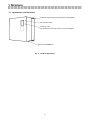
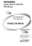
1-1 Appearance and structure
Installation leg (two upper and lower places, detachable)
LED indication lamp
Accessory cover
(The parameter unit for the inverter can not be installed.)
Main body of MT-RC unit
Fig. 1
Product appearance
2
2 Unpacking inspection
2
Unpacking inspection
During unpacking inspection, check the following points.
(1) Checking the rating nameplate on the power regenerative converter, verify that the model is as ordered.
(2) Check for damage during transportation.
(3) Verify that the reactor model is as shown below.
Regenerative
converter model
Reactor
MT-RCL model
MT-RC-H75K
MT-RC-H160K
MT-RC-H220K
MT-RC-H280K
MT-RCL-H75K
MT-RCL-H160K
MT-RCL-H220K
MT-RCL-H280K
If any obscure point or damage is found among the above, contact your dealer or our nearest sales office.
3
3 Installation
3
Installation
3-1 Transportation
Carefully handle the power regenerative converter against a damage.
Here, don't lift it to apply any force to
the surface cover alone.
3-2 Installation site
(1) For installation, avoid the following places.
Place exposed to direct sunlight, high temperature or high humidity. Place with oil mist, cotton or dust
suspended.
Place splashed with water, oil or grinding liquid.
corrosive gas.
Place with inflammable gas.
Place with falling iron powder.
Place with
Place with vibration applied.
(2) When installing the power regenerative converter in the fully enclosed panel, check whether the cooling
system and panel dimensions are sufficiently considered against heating of the converter itself or not.
In addition to the power regenerative converter, it is the important check point the ambient temperature of
the inverter installed in the same panel is within the tolerance.
(3) For continuous regenerative operation with the converter installed in the panel, apply the method of Item
3-4.
3-3 Installation direction and space
(1) Securely install the converter on the play-free installation surface with the bolts to be vertical (the letters of
the model MT-RC on the nameplate is visible from the front).
(2) Since the power regenerative converter generates heat, assure the sufficient surrounding space to
prevent the heat from being accumulated.
(3) Don't arrange the power regenerative converter and inverter to vertical in line.
(Otherwise, the warmed air will be sucked to cause overheating.)
Wiring duct
20cm or more
Clearance
10cm
or
more
15cm
or
more
Cooling
wind
When arranging the wiring
duct and so on, prevent the
cooling wind from being
hindered.
Integrated
cooling fan
Clearance
20cm or more
Surrounding space
Wiring duct
● Cautions for ambient temperature
Since the service life of the product is largely influenced
by the ambient temperature, verify that the ambient
temperature does not exceed the tolerable value (50°C)
after installation in the position shown in the right.
Measurement
position
4
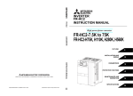
3-4 Removal/installation of heat radiation fin section
If any regenerative state continues long in the winding operation, elevation operation and others in which a
minus torque is applied for a long time, the power regenerative converter will generate much heat.
If it is stored in the panel during such operation, the temperature in the panel will excessively rise.
Therefore,
it is recommended to install the power regenerative converter, exposing the heat radiation section outside as
shown in Fig.2.
For this countermeasure, the installation leg can be replaced on the power regenerative converter MT-RC.
Preparation
• Produce the holes on the storage panel. …… For the machining hole dimensions, refer to P23 and P24.
• Reposition the installation leg (at two upper and lower places). …… Refer to Fig. 3.
Storage panel
Panel
inside
Panel
outside
Installation leg
Power
regenerative
converter
Position of installation
leg at shipment from
factory
Heat
radiation fins
Cooling fan
Installation leg
Fig. 2
Method to install the heat radiation section
outside the panel
Fig. 3
Reposition of installation leg
Note: The cooling fan is provided in the cooling section which is positioned outside the panel. Moreover, the
section installed in the panel and the cooling section are not completely enclosed. Accordingly, don't
use it in the poor environments of water drip, oil mist, dust, corrosive gas or similar.
5
4 Wiring
|
|
|
|
|
|
|
|
|
|
|
|
|
|
|
|
|
|
|
|
|
|
|
|
|
|
|
|
|
|
|
|
|
|
|
|
|
|
|
|
|
|
|
|
|
|
|
|
|
|
|
|
|
|
|
|
|
|
|
|
|
|
|
|
|
|
|
|
|
|
|
|
|
|
|
|
|
|
|
|
|
|
|
|
|
|
|
|
|
|
|
|
|
|
|
|
|
|
|
|
|
|
|
|
|
|
|
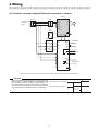
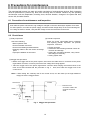
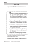
4-1 Terminal connection diagram(The basic connection is shown.)
Inverter *
MC
MCCB
U
R/L1
Three-phase
AC power
supply
S/L2
V
T/L3
W
IM
R1/L11
S1/L21
DCL
P1
P1
P/+ N/
P
MT-RCL
R
R2
S
S2
T
T2
P
N
R2
Reset signal
RES
STF
SD
S2
C
T2
B
A
R
Alarm signal
S
RDY
T
Ready signal
R1
SE
S1
MT-RC
*Don't use any other converter except MT-A, MT-V, FR-A500L, FR-F500L, and FR-A700, FR-F700 Series.
CAUTION
⋅ When using either the FR-A700 series or FR-F700 series
with the MT-RC, install a magnetic contactor(MC) at the Inverter input power supply (MC)
input side of the inverter and power on the inverter 1s or
more after powering on MT-RC. When power is supplied to
the inverter before the MT-RC, the inverter and the MT-RC MT-RC power supply (MCCB)
may be damaged or the MCCB may trip or be damaged.
ON
ON
1s or more
6
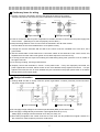
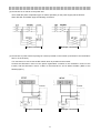
● Cautionary items for wiring
(1) Properly connect the terminals P and N to the terminals P and N of the inverter.
If they are improperly connected, the power regenerative converter will be broken.
Inverter
Inverter
【Proper connection】
【Improper connection】
(2) If the AC reactor MT-BAL for power cooperation is installed, be sure to connect it to the power supply side
of the inverter. (Referring to P9, don't improperly connect them.)
(3) Keep the wiring distance of 5m or less across the terminals P and N of the inverter.
Use the cables of the recommended size or more (Refer to P25).
(4) Though the common terminals SD and SE of the control circuit are insulated from each other, don't
ground them.
(5) Use the shield cable or twist cable as the connection cables to the terminals of the control circuit, and
separate them from the main circuit (power circuit, 200V sequence circuit and so on).
(6) To surely prevent the wire chips from entering the inside during wiring work, place the cover or similar on
the upper vent hole.
(7) For secure grounding, use the ground terminal.
(8) Properly connect the terminals R, S and T in the phase order. If they are improperly connected, the
power regenerative converter will be broken or the circuit breaker will trip against overcurrent. If it trips
against overcurrent, be sure to check whether they are connected in the proper phase order or not before
turning ON the power supply again.
● Design information
(1) Arrange NFB and MC to surely make the power regenerative converter previously turned ON when
the power supply is turned ON.
【Proper connection】
【Improper connection】
(2) Do not apply a large voltage to the contact input terminals (RES) of the control circuit.
(3) Do not apply a voltage directly to the alarm output signal terminals (A, B, C).
Always apply a voltage to these terminals via a relay coil, lamp, etc.
(4) Since the input signals to the control circuit are on a low revel, use two parallel micro signal contacts or a
twin contact for contact inputs to prevent a contact fault.
7
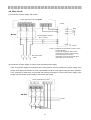
4-2 Main circuit
(1) Connection of power supply and inverter
Power regenerative converter MT-RC
AC power input terminal
Inverter
Motor
MT-RCL
Electromagnetic contactor
(MC)【Note.1】
Ground
【Note.1】Install the electromagnetic contactor on the
inverter side alone.
(If the power supply side of the power
regenerative converter is opened during
power regeneration, the power
regenerative converter will sometimes be
turned OFF due to overcurrent.
Non-fuse breaker
(NFB)
(2) Connection of power supply of control circuit to another power supply
If MC of the power supply is turned OFF when the protective circuit is activated, the power supply of the
control circuit will be turned OFF to make it impossible to hold the error signal (relay) and error indication.
If it is necessary to hold them, proceed with the following procedure to connect the power supply of the
control circuit to another power supply or the primary side of MC.
Power regenerative converter
MT-RCL
Inverter
8
(3) Connection of AC reactor to the power side
Don't install the power cooperation type AC reactor (MT-BAL) on the power supply side of MT-RCL.
When MT-BAL is installed, apply the following connection.
Inverter
Inverter
【Proper connection】
【Improper connection】
(4) Connection of power-factor improving DC reactor provided on the inverter (Connection to the terminals P
thru P1 of the inverter)
For connection, be sure to use the DC reactor which is provided on the inverter.
Connect the terminals P and N of the power regenerative converter to the terminals P and N of the
inverter, and the terminals U and X of DCL to the terminals P1 and P without mistake. (Refer to the
following figure.)
Inverter
Inverter
【Proper connection】
【Improper connection】
9
4-3 Control circuit
(1) Input signal
(2) Output signal
Reset
Abnormal output
(1C contact output)
Ready output
(Open collector output)
●Cautionary items for connection to sequencer
●Countermeasure
If the control power voltage in the inverter
(1) Insert the diode which prevents the sneak
current.
becomes higher than the external power
voltage of the sequencer when the sequencer
output unit (open collector output) and MT-RC
(2) Use the output unit of all-point independent
type.(Example: AY40A, etc.)
are connected, the dot-lined current will flow
to give the command signal to the inverter
(3) The external power supply becomes higher
than the control power supply of the power
regenerative converter.
even though the transistor of the sequencer is
not turned ON.
Diode for
countermeasure
Photo
coupler
External
power
supply for
MELSEC
Sequencer MELSEC-A
Photo
coupler
MT-RC
10
Control power
supply
(+24V)
4-4 Connection example
(1) Combination of brake motor and power regenerative converter (MT-RC)
(Application for elevation
equipment and so on)
• In combination with the brake motor, it is also applicable for the elevator equipment. It is used in
combination with MT-RC type power regenerative converter.
• Since it sometimes slips down on the elevation equipment at the start time, it is necessary to delay the
release timing of the brake. Against such a case, the brake is released with the frequency arrival signal
(FU).
Forward turn
Reverse turn
Output frequency
Setting value in Pr. 42.
Brake release
Note 1: The AC reactor (MT-BAL) for power cooperation is necessary in the following cases.
• The ratio between power capacity and inverter capacity is 10 times or more
• The rectifier load is present in the same power supply.
• The phase-adavance capacitor is present in the same power supply.
Note 2: The terminals STF and SD of the power generative converter (MT-RC) is normally short-circuited.
Note 3: LS indicates the upper/lower limit switch of the machine.
Note 4: MC1X is the auxiliary contact of the contactor MC1.
Note 5: Be sure to separate the SD terminals of the inverter unit and power regenerative converter from each
other.
11
12
Special Class 3 ground
under 10 0hm
AC380∼460V
Power supply
Power Regenerative
Converter
MT-RC
(Note 5)
(Note 2)
Reset
(Note 1)
Stop
(Note 3)
Descent
Ascent
(Note 4)
Combination of brake motor and power regenerative converter (MT-RC)
(Application for elevation equipment and so on)
Connection example
Reset
(Note 5)
(Note 5)
Inverter
MT-A
MT-V
FR-A
FR-F
Special Class 3 ground
under 10 0hm
Brake
DC24V
5 Operation
5
Operation
5-1 Inspection before operation
After installation and wiring, check the following before turning ON the power supply.
(1) Is any error present in the wiring.
Is it properly wired particularly on the terminals P and N of the main
circuit?
(2) Is any wire chip left inside after the cable connecting work? Is it also short-circuited with wire chip or
similar?
(3) Is it skipped to fasten any terminal screw, or it is loose?
(4) Check the phase order of the power supply, and verify that any wrong connection is not present on the
power terminals R2, S2 and T2, and the phase power terminal R, S and T.
※ Set the parameters of the inverter to make the power regeneration possible.
• Set "1" at Pr. 30. (Regenerative operation is selected.)
• Set "100" at Pr. 70. (Set the operation rate% ED. Be sure to set "100" when MT-RC is used.)
• Set the motor rating at Pr. 3 and 19. (Excessive excitation is prevented during regeneration.)
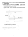
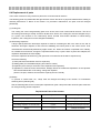
5-2 Operation example (Case of load with power running during acceleration and
constant speed and regeneration during deceleration)
Preparation
• Turn OFF the start signal of the inverter.
• Zero the signal of the frequency command of the inverter.
• Power supply ON
• Start
• LED lamp on the unit is lit.
• The cooling fan starts running.
• The ready signal is turned ON.
Turn ON NFB and MC.
↓
Turn ON the operation signal
of the inverter.
↓
• Acceleration
• Constant speed
Gradually increase the
frequency command of the
inverter to the max. speed.
• Deceleration
Turn OFF the operation signal
of the inverter.
The revolution speed of the motor is increased
to the constant speed.
↓
The revolution of the motor slows down, and
stops.
The regenerative power LED indicates the
regenerative power in %.
> Check point
• Does the regenerative power LED indicate any proper value?
Since the regenerative operation may not be
proper, check the wiring and the constant
setting value for the inverter.
• Does the regenerative power indication exceed 100%?
※The regenerative power indicator (% indication) includes
an error of approx. 5%.
If this state continues long, it may trip since the
capacity is exceeded.
• Is the trouble indicator lit?
Referring to Item "Protective function", inspect
the cause.
13
6 Precautions for maintenance
6
Precautions for maintenance
The transistorized inverter is a static unit mainly consisting of semiconductor devices. Daily inspection
must be performed to prevent any fault from occurring due to adverse influence by the operating
environment, such as temperature, humidity, dust, dirt and vibration, changes in the parts with time,
service life, and other factors.
6-1 Precautions for maintenance and inspection
Even after the power is shut down, high voltage is charged on the inner electrolytic capacitor for a while.
For the inspection, turn OFF the power supply, and wait until the charge lamp on the control board goes
out. Using the tester or similar, verify that DC voltage across the terminals P and N is 0V.
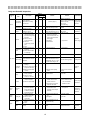
6-2 Check items
(1) Daily inspections
(2) Periodic inspection
Check the following:
Check the areas inaccessible during operation
and requiring periodic inspection. For periodic
inspection, consult us.
• Motor operation fault
• Unusual vibration and noise
• Unusual overheating and discoloration
• Cleaning of filter in the vent section of storage
panel
• Improper installation environment
• Screws and bolts
• Conductors and insulating materials: Check for
corrosion and damage.
• Cooling fan, smoothing capacitor, relay: Check
and change if necessary.
• Cooling system fault
(3) Megger test procedure
• Before the megger test of the power system, disconnect the cable which is connected to the power
regenerative converter, in order to prevent the test voltage from being applied.
• Take the megger test of the power regenerative converter itself, keeping the terminal block of the
main circuit short-circuited with the procedure in Fig. 4. Here, don't take the megger test of the
control circuit.
Note 1: When taking the continuity test of the control circuit, use the tester (in the high-resistance
range) but not the megger buzzer.
Short circuit
Inverter
…………Disconnect the
connection cable of the
dot-lined connection
cable.
Power
Megger
Fig. 4
Megger test procedure
14
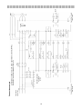
Daily and Periodic Inspection
Area of
Inspec-tio
n
Inspection
Item
Interval
Description
Daily
Periodic
1
year
Method
Criterion
Instrument
2
years
Ambient temperature:
Surrounding
environment
10ºC to + 40ºC, non-freezing. Thermometer
Check ambient
temperature, humidity,
(Refer to page 4)
{
dust, dirt, etc.
Ambient humidity:
, hygrometer,
90% or less,
recorder
non-condensing.
General
Overall unit
Check for unusual
vibration and noise.
Power supply
Check that main circuit
voltage
voltage is normal.
{
{
(1) Check with megger
{
{
Visual and auditory checks.
No fault.
Measure voltage across
323V to 506V
Tester, digital
inverter terminals R2, S2, T2.
50Hz / 60Hz
multimeter
(1) Disconnect all cables from
(1) 5M Ω or more.
(across main circuit
inverter and measure
terminals and ground
across terminals R2, S2,
T2 and ground terminal
terminal).
General
(2) Check for loose
(2) Re-tighten.
screws and bolts.
(3) Check for
500VDC
with megger.
{
{
(3) Visual check.
{
(1), (2) Visual check.
(2), (3) No fault.
class megger
overheat-ing of each
part.
(4) Clean.
(1) Check conductors for
Conductors,
cables
(1), (2) No fault.
distortion.
(2) Check cable sheaths
{
for breakage.
Terminal
block
Check for damage.
Visual check.
{
{
Main circuit
IGBT module
No fault
Disconnect cables from
Check resistance across
inverter and measure across
terminals.
terminals R2, S2, T2, ⇔ and
(See the following pages)
Analog tester
P, N with tester range of 1Ω.
(1) Check for liquid
(1), (2) Visual check.
{
(1), (2) No fault.
leakage.
Smoothing
capacitor
(2) Check for safety valve
Capacity
{
meter
projection and bulge.
(3) Measure with capacity
(3) Measure electrostatic
capacity.
Relay
meter.
{
(1) Check for chatter
{
during operation.
(2) Check for rough
(3) 85% or more of rated
capacity.
(1) Auditory check.
(1) No fault.
(2) Visual check.
(2) No fault.
(1) Visual check. Cement
(1) No fault.
{
surface on contacts.
(1) Check for crack in
{
resistor, Wire wound
resistor insulation.
Resistor
(2) Check for open cable.
resistor and so on.
{
(2) Disconnect one end and
(2) Error should be within
±10% of indicated
resistance value.
Tester, digital
multimeter
measure with tester.
(1) Perform sequence
Control
Operation
circuit
check
{
(1) Simulatively connect or
protective operation
disconnect inverter
test to make sure of
protective circuit output
no fault in protective
terminals.
(1) Fault must occur because
of sequence.
(1) Check for unusual
system
Cooling fan
(1) Turn by hand with power
{
multimeter,
rectifier type
voltmeter
and display circuits.
Cooling
Digital
(1) Smooth rotation.
off.
vibration and noise.
(2) Check for loose
{
(2) Re-tighten
(2) No fault.
connection.
(1) Check if LED lamp is
Display
(2) Clean with rag.
(2) Clean.
Display
Check that reading is
Meter
(1) Check that lamps are lit.
{
blown.
normal.
{
{
Check reading of meters on
Must satisfy specified and
Voltmeter,
panel.
management values.
ammeter,
etc.
15
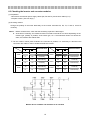
6-3 Checking the inverter and converter modules
(1) Preparation
• Disconnect the external power supply cables (R2, S2 and T2) and inverter cables (P, N).
• Prepare a tester. (Use 1Ω range.)
(2) Checking method
Change the polarity of the tester alternately at the inverter terminals R2, S2, T2, P and N, check for
continuity.
Note:1. Before measurement, check that the smoothing capacitor is discharged.
2. At the time of continuity, the measured value is several to several ten’s-of ohms depending on the
module type, quantity in parallel, circuit tester type, etc. If all measured values are almost the
same, the modules are without fault.
※ On the model in which plural modules are connected in parallel, it is necessary to disconnect the
connection bus cable in order to isolate the defective module.
Tester Polarity
+
−
R2
P1
Discontinuity
TRRP
IGBT module
Tester Polarity
Measured Value
Measured Value
+
−
R2
N
Continuity
N
R2
Discontinuity
S2
N
Continuity
N
S2
Discontinuity
T2
N
Continuity
N
T2
Discontinuity
TRRN
P1
R2
Continuity
S2
P1
Discontinuity
TRSP
TRSN
P1
S2
Continuity
T2
P1
Discontinuity
TRTP
TRTN
P1
T2
Continuity
Module device numbers and terminals to be checked
16
6-4 Replacement of parts
The inverter consists of many electronic parts such as semiconductor devices.
The following parts may deteriorate with age because of their structures or physical characteristics, leading to
reduced performance or failure of the inverter. For preventive maintenance, the parts must be changed
periodically.
(1) Cooling fan
The cooling fan cools heat-generating parts such as the main circuit semiconductor devices. The life of
the cooling fan bearing is usually 10,000 to 35,000 hours. Hence, the cooling fan must be changed every 2
to 3 years if the inverter is run continuously. When unusual noise and/or vibration is noticed during
inspection, the cooling fan must be changed immediately.
(2) Smoothing capacitors
A large-capacity aluminum electrolytic capacitor is used for smoothing the DC in the main circuit, and an
aluminum electrolytic capacitor is also used for stabilizing the control power in the control circuit. Their
characteristics are adversely affected by ripple current, etc. When the inverter is operated in an ordinary,
air-conditioned environment, change the capacitors about every 5 years. When 5 years have elapsed, the
capacitors will deteriorate more rapidly.
Check the capacitors at least every year (less than six months if their life will be expired soon).
Check the following:
1) Case (side faces and bottom face for expansion)
2) Sealing plate (for remarkable warping and extreme cracks)
3) Explosion-proof valve (for excessive valve expansion and operation)
4) Appearance, external cracks, discoloration, leakage. When the measured capacitance of the capacitor
has reduced below 85% of the rating, change the capacitor.
(On the new part, measure and record the capacity across P and N.)
(3) Relays
To prevent a contact fault, etc., relays must be changed according to the number of accumulative
switching times (switching life).
See the following table for the inverter parts replacement guide. Lamps and other short-life parts must also
be changed during periodic inspection.
Replacement Parts of the Inverter
Part Name
Standard Replacement Interval
Description
Cooling fan
2 to 3 years
Change (as required)
Smoothing capacitor in main circuit
5 years
Change (as required)
Smoothing capacitor on control board
5 years
Change the board (as required)
Relays
Change as required
17
7 Troubleshooting
7
Troubleshooting
If any trouble should occur to impair the function of the equipment, isolate the cause and take the remedy
referring to the following inspection content.
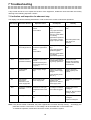
7-1 Indication and inspection for abnormal stop
The display unit has the following indications in order to inform the causes of abnormal operations.
LED display
Protective function
E. OC2
Overcurrent shut-off
Operation cause
Check point
Excessive regenerative
current
Does any load rapidly
vary?
Power failure
Is any rapid slowdown
operation applied?
Remedy
Lengthen the slowdown
time.
Does any power failure
occur during
regenerative operation?
E. OV2
Regenerative
overvoltage shut-off
Excessive DC voltage
Excessive regenerative
power
Power failure
E. THT
Overload shut-off
(Transistor thermal)
E. UVT
Undervoltage
protection
Is any phase of power
supply in proper order?
Check the phase order,
and correct it if
improper.
Does any load rapidly
vary?
Lengthen the slowdown
time.
Is any rapid slowdown
operation applied?
Does any power failure
occur during
regenerative operation?
Excessive regenerative
current
(Current flows beyond
the specified value for a
long time.)
Power supply voltage
drop
Does any regenerative
overload state continue
long during operation?
Reduce the load.
Is there any cause to
drop the power supply
voltage?
Inspect the power
supply capacity and
system.
Change the operation
content to shorten the
overload time.
(Large-capacity motor
start, etc.)
E. GF
Ground fault
overcurrent
protection on the
power supply side
Ground fault on the
power supply side
Is any ground fault
present on the
equipment or cable of
power supply side?
Isolate the ground fault
place.
E. FIN
Cooling fin overheat
protection
Overheat of cooling fin
Is cooling fin troubled?
Temperature rise in the
unit
Is fin or filter clogged?
Inspect and recover
cooling fin.
Overcurrent of cooling
fan
Inspect cooling fan.
E. FAN
Cooling fan stop
Clean fin, filter and other
cooling air path.
Inspect and recover
cooling fin.
Replace cooling fan.
Note: If any above trouble is indicated, the power regenerative converter will stop running. Accordingly, the
protective function "overcurrent" or "overvoltage" will be activated also on the inverter side.
To restart the operation, isolate and remove the cause, and reset the system.
18
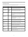
7-2 Protective functions
Though the following protective functions are provided for the power regenerative converter to protect itself, it
may be activated if any trouble occurs in the power regenerative converter.
Function name
LED display
Content
Overcurrent shut-off
E. OC2
If any regenerative current of the converter unit exceeds approx.
300% of the rated current, the protective circuit will be activated to
stop output of the power regenerative converter.
Arm short-circuit
E. ATT
E. OC2
Alternate
display
The arm short-circuit occurs across P and N of the transistor.
of the power regenerative converter is stopped.
Regenerative overvoltage
shut-off
E. OV2
If any DC voltage of the main circuit in the power regenerative
converter exceeds 138% of the rated voltage, the protective circuit will
be activated to stop output of the power regenerative converter. It is
sometimes activated by the surge voltage which occurs in the power
supply system.
Overload shut-off
E. THT
If any current exceeds 100% of the rated output current but the
overcurrent shut-off (OC) is not activated, the electronic thermal relay
will be activated due to the reverse time properly in order to protect
the main circuit transistor, thus stopping output of the power
regenerative converter.
(Overload suppression
150% 60 seconds)
Undervoltage protection
E. UVT
If any power supply voltage becomes approx. 300VAC or less, output
of the power regenerative converter will be stopped.
Ground fault overcurrent
protection on the power
supply side
E. GF
If any ground fault overcurrent flows because of the ground fault on
the power supply side of the power regenerative converter, output of
the power regenerative converter will be stopped.
CPU error
E. CPU
If the integrated CPU does not complete its operation within the
specified time, it will be self-diagnosed as an error, thus stopping
output of the power regenerative converter.
Cooling fin overheat
protection
E. FIN
If the cooling fin is overheated since the cooling fin is troubled to stop
or the fin is clogged, the thermosensor will be activated to stop output
of the power regenerative converter.It will be also activated if the air
temperature in the unit rises.
Cooling fan stop
E. FAN
The cooling fan stops due to an abnormality.
regenerative converter is stopped.
19
Output
Output of the power
8 Specifications
8
Specifications
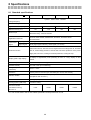
8-1 Standard specifications
Model
MT-RC-□
H75K
Rated input power supply
H160K
3-phase
voltage/frequency
Tolerable voltage fluctuation
H220K
380V to 460V
323V to 506V
H280K
50/60Hz
50/60Hz
Applicable motor capacity
75
90 to 160
185 to 220
250 to 280
Rated current (A) ※1
102
218
300
382
Continuous rating : 100%
Brake torque
Short-time rating : 150% 60 seconds
Applicable control unit
MT-A140, A240, A140E, A240E Series, FR-A540L, FR-F540L Series
MT-V240 Series
Input/output
Input signal
Reset signal
signal
output signal
Ready signal (Open collector), Alarm signal, (1C contact)
Overcurrent shut-off, Arm short-circuit, Regenerative overvoltage shut-off, Overload
Protective function
shut-off, Undervoltage protection, Ground fault overcurrent protection on the power
supply side, CPU error, Cooling fin overheat protection, Cooling fan stop
Display (LED 4-digit display)
% display of regenerative power (including an error of ± 5%), display of error
content
Ambient temperature
-10ºC to + 50ºC (non-freezing)
Ambient humidity
90 % RH or less (non-condensing)
Storage temperature
(JEM1030)
Ambience
-20ºC to + 65ºC
Indoors (free from corrosive gas, flammable gas, oil mist, dust and dirt)
2
Altitude, vibration
Altitude of 1000m or less, 5.9m/s {0.6G} or less
(Compliance with JIS C0911)
Protective structure
Open type (IP00)
Cooling system (JEM 1030)
Forced air cooling
AC reactor model
(standard accessory)
H75K
H160K
H220K
MT-RCL-□
※1: The current flows in the AC bus cables (terminals P and N) of the main circuit.
20
H280K
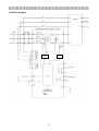
8-2 Block diagram
Inverter
Current
detection
Voltage
detection
Current
detection
Phase detection
Power Regenerative Converter MT-RC
Error output
Ready output
Display
LED
21
To motor
8-3 Terminal specifications
Type
Terminal
code
AC reactor
R
S
T
S2
P
N
R2
Regenerative converter unit
Rating
AC power supply
input terminals
S2
T2
R
S
T
R1
S1
Regenerative converter unit
Terminals are connected to the same
input power of the inverter.
3-phase
50/60Hz
Power regenerative
converter connection
terminal
Converter input
terminals
Terminals are connected to the terminals
R2, S2 and T2 of the power regenerative
converter.
Terminals are connected to the terminals
P and N of the inverter.
―
AC reactor
connection terminals
Terminals are connected to the terminals
R2, S2 and T2 of the AC reactor.
3-phase
Power phase
detection terminals
Terminals are connected to the same
input power of the inverter.
380V to 460V
50/60Hz
Connected to the power phase detection
terminals R and S with short bar. To hold
the error display, disconnect the short
bars and input the power supply from
outside.
Power supply
terminals for control
circuit
Ground terminal
Control circuit type
Content
380V to 460V
R2
T2
Main circuit type
Terminal name
For ground earth
―
STF
Test mode terminal
Input resistor
RES
Reset input terminal
when STF to SD circuit is
shorted
SD
Contact input
common terminal
4.7kΩ
when RES to SD circuit is
shorted
DC
4 to 6 mA
Circuit between terminals STF and SD is
normally shorted.
The input terminal is used to reset the
protected state when the protective circuit
is activated. After shorting RES to SD
circuit 0.1 second or more, open it, and it
will be ready for resetting.
Output signal to indicate that the
protective circuit is activated.
A
B
1C contact
Error output terminal
C
・ Normal time
200VAC 0.3A
30VDC
B to C : Closed
A to C : Open
0.3A
・ Abnormal time B to C : Open
A to C : Closed
RDY
Ready output
terminal
SE
RDY common
terminal
Tolerable load
collector output
24VDC
0.1A
22
of
open
Output signal indicates that the power
regenerative converter is ready for
operation.
L operation when readiness is completed.
9 Dimensional outline drawing
9
Dimensional outline drawing
MT-RC-H75K
When cooling fin is positioned outside the panel
Air exhaust
Hole for hanger
Mounting
hole
Square hole
Accessory cover
(Parameter unit is not
usable.)
M4-8 screw
Air suction
M10 screw
(Ground terminal)
Control cable inlet port
MT-RC-H160K
When cooling fin is positioned outside the panel
Air exhaust
Hole for hanger
Mounting
hole
Accessory cover
(Parameter unit is not
usable.)
Air suction
2-M10 screw
(Ground terminal)
Control cable inlet port
23
M4-8 screw
MT-RC-H220K
When cooling fin is positioned outside the panel
Air exhaust
Hole for hanger
Mounting
hole
Accessory cover
(Parameter unit is
not usable.)
Air suction
M6-8 screw
M10-2 screw
Control cable inlet port
(Ground terminal)
MT-RC-H280K
When cooling fin is positioned outside the panel
Air exhaust
Hole for hanger
Mounting
hole
Accessory cover
(Parameter unit is
not usable.)
M6-8 screw
Air suction
M20-2 screw
(Ground terminal)
Control cable inlet port
24
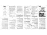
9-1 Selection of peripheral equipment
(1) Referring to "Instruction Manual for Inverter", select the non-fuse breaker (NFB) and electromagnetic
contactor (MC) depending on the capacities of the motor and inverter.
2
(2) On the connection cables to the power regenerative converter, select the cable size(mm ) which is larger
than specified in the following table.
Cable size
Model
MT-RC
Applicable motor capacity
(kW)
R2/S2/T2
R/S/T
P/N
MT-RC-H75K
75
60
2
60
MT-RC-H160K
90
60
2
80
MT-RC-H160K
110
80
2
100
MT-RC-H160K
132
100
2
100
MT-RC-H160K
150
125
2
150
MT-RC-H160K
160
125
2
2x100
MT-RC-H220K
185
150
2
2x100
MT-RC-H220K
200
2x100
2
2x100
MT-RC-H220K
220
2x100
2
2x100
MT-RC-H280K
250
2x125
2
2x150
MT-RC-H280K
280
2x125
2
2x150
The table is based on the characteristics of the standard motors of Mitsubishi Electric Corp..
(3) Select MT-BSL and MT-BAL according to the capacity of the inverter.
(4) Since MT-RCL is attached to MT-RC, be sure to use the attached one.
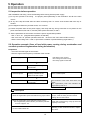
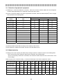
9-2 Model selection
According to the motor capacity and brake torque strength, select the model as shown in the following table.
• Don't use MT-RC whose capacity is larger than combined in the following table.
(Even if the capacity of MT-RC is increased, the continuous brake torque will not exceed 100% of the
motor rating.)
Brake torque (%) for continuous rating
(% with the rated torque of the motor regarded as 100%)
Motor capacity (kW)
75
90
110
132
150
160
185
200
220
250
280
Inverter model
75K
110K
110K
160K
160K
160K
220K
220K
220K
280K
280K
MT-RC-H75K
100
80
65
55
50
45
40
35
30
30
25
MT-RC-H160K
―
100
100
100
100
100
85
80
70
60
55
MT-RC-H220K
―
―
―
―
―
―
100
100
100
85
75
MT-RC-H280K
―
―
―
―
―
―
―
―
―
100
100
25