1
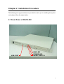
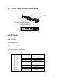
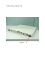
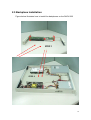
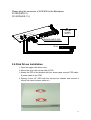
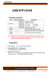
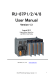
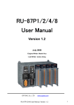
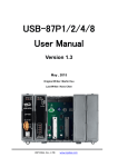
RACK-232 CHASSIS
USER’S MANUAL
Copyright Notice
This document and product is copyrighted, January 2000, by ICP Electronics Inc.
All rights are reserved. No part of this manual may be reproduced, copied, or
translated without prior notice to ICP Electronics Inc.
The information provided in this document is for reference only. We do not assume
any responsibility arising out of the application of the products. This manual is
subject to change without any notice.
RACK-232, ICP are trademark of ICP Electronics Inc.
1
Table of Contents
Chapter 1
Product Information
1.1 General Information
1.2 Product Specifications
1.3 Dimensions
Chapter 2
System Setup
2.1 Front Panel of RACK-232
2.2 LP-01 Control Panel of RACK-232
2.3 Rear Panel of RACK-232
2.4 Removing the chassis cover
2.5 Backplane Installation
2.6 Disk Drives Installation
2.7 Power Supply Installation
2.8 Fan Installation
Appendix A
Passive Backplane
Appendix B
Exploded Diagram
2
Chapter 1 Product Information
1.1 General Information
RACK-230A IPC chassis is a rugged PC/AT compatible computer designed for the
factory floor and other Industrial harsh environment. RACK-230A features 2 slots
Passive Backplanes and high reliability ACE-890 series power supply.
The chassis can easily be installed on 19" Rack or Desktop with the supplied
brackets.
1.2 Product Specifications
General specification
- Construction
- Disk Driver
:
:
- Cooling Fan
- Indicator
- Dimension
- I/O Port
-Reset Buttom
-Buzzer
:
:
:
:
:
:
Heavy-duty Consideration
One 5.25” CD-ROM ,One 3.5” FDD Drive and One 3.5” HDD
or Two 2.5” HDD drives spaces.
Triple Ball bearing fans
Two LEDs to monitor the status of HDD and Power Supply
483 x 486 x 44 ( W x D x H )
One USB Port (Type A)
Yes
Yes
Passive Backplanes (Optional)
PCI-2SD – 2 slot ISA/PCI bus Backplane (VER:1.3)
IP-2SD – 2 slot PCISA bus Backplane(VER:2.1)
Power Supply
Standard equipped power supply for the RACK-232 is : ACE-890A.
Optional: ACE-890P 70V-132VDC input power supply.
ACE-890T 36V-72VDC input power supply.
ACE-890C 18V-36VDC input power supply.
ACE-890V 9V-16VDC input power supply.
3
Working Environment
- Operating Temperature
- Relative Humidity
- Vibration
:
:
:
- Shock
- Safety approval
:
:
0~50°C
5~95% Relative
5-17Hz, 0.1” double amplitude displacement
17-640Hz, 1.5G acceleration peak to peak
10G acceleration peak to peak
meet CE, FCC
Cooling Fan
Triple rear ball bearing cooling fans.
Drive Capacity
One 5.25” CD-ROM,one3.5” FDD and one 3.5” HDD drive spaces or two 2.5” HDD
Drives spaces.
4
487.70
1.3 Dimensions
UNIT:mm
32
44.50
483
465
431
5
Chapter 2 Installation Procedure
The following set up procedures are provided to assist you in installing the system
unit, please follow the steps below:
2.1 Front Panel of RACK-232
USB PORT
HDD LED
POWER LED
RESET SWITCH
6
2.2
LP-01 Control Panel of RACK-232
RESET SWITCH
BUZZER
POWER LED(GREEN)
HDD LED(RED)
1 2 3 4 5 6 7 8 Pin
LP-01 Panel
BZ1: BUZZER
D1:POWER LED
D2: System HDD LED
SW1: RST system reset button
CN1:
1
8
Pin #
FUNCTION
1
2
3
SPEAKER (+)
SPEAKER (-)
POWER LED (-)
4
5
6
7
POWER LED (+)
HDD LED(-)
HDD LED(-)
RESET (1)
8
RESET (2)
7
2.3 Rear Panel of RACK-232
AC INPUT
8
2.4 Removing the chassis cover
The cover is mounted by five screws on the top of the chassis, remove them
and slide the cover to the rear of the chassis. Figure below shows how to
remove the chassis cover.
9
2.5 Backplane Installation
Figure below illustrates how to install the backplanes on the RACK-232
STEP 1
STEP 2
10
Please plug the connector of ACE-890 to the Backplane
IP-2SD(VER:2.1)
PCI-2SD(VER:1.3)
ZER
BUZ
ACE-890
POWER
SUPPLY
H
WITC
ET S
N)
RES
REE
(G
D
E
ER L
POW
ED)
LED(R
HDD
BACKPLANE:IP-2SD
IP-52
2.6 Disk Drives Installation
1. Open the upper disk drive cover.
2. Mount the drive rails on the side of FDD
3. Attach the FDD to the bracket with four screws and connect FDD cable
& power cable to the FDD.
4. Directly fix the 3.5” HDD with four screws into chassis and connect a
40-pin flat cable & power cable to it.
11
Three screws this side
FDD
CD ROM
12
2.7 Power Supply Installation
13
2.8 Fan Installation
14
PASSIVE BACKPLANES
0
238.3
APPENDIX A
239.3
0
9.77
0
6-O4.0
41.26
34.5
33.26
18.5
17.69
8.5
0
261
253.5
0
5.5
99.5
223.1
0
37.9
21.7
0
IP-2SD VER:2.1
0
17.69
MODEL:PCI-2SD VER:1.3
33.26
5-O4.0
41.26
34.5
18.5
255.5
261
161.5
22.7
0
7.5
8.5
0
PCI-2SD VER:1.3
15
APPENDIX B
EXPLODED DIAGRAM
16