1
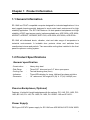
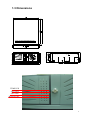
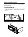
EC-1040 CHASSIS
USER’S MANUAL
Copyright Notice
This document and product is copyrighted, May 2001, by ICP Electronics Inc. All
rights are reserved. No part of this manual may be reproduced, copied, or translated
without prior notice to ICP Electronics Inc.
The information provided in this document is for reference only. We do not assume
any responsibility arising out of the application of the products. This manual is
subject to change without any notice.
EC-1040 is trademark of ICP Electronics Inc.
1
Table of Contents
Chapter 1
Product Information
1.1 General Information
1.2 Product Specifications
1.3 Dimensions
Chapter 2
System Setup
2.1 Filter of the Lockable Door
2.2 The Front Panel of EC-1040
2.3 Removing the chassis cover
2.4 Disk Drives Installation
2.5 Fan Installation
2.6 Power Supply Installation
2.7 The Card Clamp & Backplane Installation
Appendix A
Passive Backplane
Appendix B
Power supply
Appendix C
Drive Bay
2
Chapter 1 Product Information
1.1 General Information
EC-1040 is a PC/AT compatible computer designed for industrial applications. It is a
steel rugged chassis specially designed to work under harsh environment for high
reliability application. The EC-1040 features 14-slots passive backplanes and high
reliability AC/DC input power supply (options available are: ACE-920A, ACE-932A,
ACE932T, ACE925T, ACE925C, ACE-916V, ACE-935A, ACE-832A, ACE-R30A…
EC-1040 will withstand shock, vibration, dust and wide range of temperature in
industrial environments. A lockable door protects drives and switches from
unauthorized misuse and particle. Two removable cooling-fans installed in the front
panel for optimum cooling system.
1.2 Product Specifications
General specification
- Construction
- Disk Driver
- Cooling Fan
- Indicators
- Dimension
:
:
:
:
:
Heavy-duty steel
Three 5.25” drive and one 3.5” drive open space.
Two ball bearing fans (8cm)
Three LEDs display for temp, LAN and fan alarm activities.
19” rackmount, 4U height, 431(W) X 177(H) X 480(D) mm
Passive Backplanes (Optional)
Features 14 slots full-length backplanes with the options: PCI-14S, PCI-14S2, PCI14S3, BP-14S, PX-14S, PX-14S2, PX-14S3, PX-14S5IP-14S and IP-14S3…
Power Supply
PS/2 type of AT/ATX power supply for EC-1040 are ACE-920A/ 932T/ 935A/ 925C/
3
916V/ 832A. For DC input power supply, you may choose: ACE-932T, ACE-925T,
ACE-925C or ACE-916V. ACE-R30A redundant power supply is optional.
Working Environment
- Operating Temperature
- Relative Humidity
- Vibration
:
:
:
- Shock
- Safety approval
:
:
0~50°C environment
5~95% Relative
5-17Hz, 0.1” double amplitude displacement
17-640Hz, 1.5G acceleration peak to peak
10G-acceleration peak to peak
meet CE, FCC
Cooling Fan
Two removable ball bearing cooling fan (8cmX8cm)
Drive Capacity
Three 5.25” drive and one 3.5” open FDD or HDD space.
Programmable Message and Alarm Function
EC-1040 provides customer a programmable display for server name, IP address,
system time, alarm message,… etc. We can use the utility tool to program message
by RS-232 port. The detail please references the section 2-7 cable management for
system internal connection. The floppy disk (A106 Utility) provides the setting
programming information.
The alarm function support system monitoring that four fan speed monitoring, two
Temp. monitoring, alarm buzzer, alarm message and customer message transfer to
LCD module.
4
1.3 Dimensions
TEMP LED
LAN LED
FAN LED
BUZZER OFF
5
Chapter 2 Installation Procedure
The following procedures are provided to assist you in installing the EC-1040,
please follow the steps below:
2.1 Drive of the Lockable Door
A lockable door installed in the front panel .The Drive is located at the inner of
the door. It should be check at least once a month to achieve optimum
performance.
6
2.2 The Front Panel of EC-1040
The drive bays, fans and power switch are in the front panel. Drive bays and
power switch are protected by lockable door for unauthorized misuse and
particle environment.
SYSTEM RESET
POWER ON/OFF SWITCH
7
EC-1040
EC-1040&DM-62M
8
EC-1040&DM-64T
LCD ON/OFF
EXIT
UP
DOWN
MENU
POWER
9
EC-1040 & DM-62M & KM-085
10
EC-1040 & KM-085
11
2.3 Removing the chassis cover
The top cover is fixed by 6 screws at each side and the top of the chassis, remove them and
slide the cover to the rear of the chassis. Figure below shows how to remove the chassis
cover.
12
2.4 Disk Drives installation
1. Open the lockable door in the front panel
2. Remove 2 screws that lock the disk drive bay
3. Pull out the disk drive bay
4. Attach the drivers to the bracket with screws and connect flat cable &
power cable to the driver
5. Plug in the drive bay and lock it by screws.
13
2.5 Fan Installation
The EC-1040 is easy to install the fan module in the chassis. It's not need any
screw. Plug in the plastic locker; connect the fan cable with the A 106 controller
board.
14
2.6 Power Supply Installation
2.6.1 General Power Supply
For the EC-1040 installation: ACE-920A/ 932A/ 932T/ 935A /925T/ 925C/ 916V/
32A…
SCREW X 2
SCREW X 3
15
2.6.2 Redundant Power Supply for the EC-1040 installation: ACE-R30A
SCREW X 2
16
2.7 The Card Clamp & Backplane Installation
Figure below illustrates how to install the backplanes on the Rack-3000.
To install the backplanes in the chassis, remove the clamp panel first, then put
the backplanes inside the chassis and screw it.
Use 2 screws(6#32*6) to fix the card clamp
17
Cable Management
1
2
EXT. VGA Cable
M TO F
32000-022301
EXT. VGA Cable
M TO M
32000-023200
3
CPU CARD
KM-085 KEYBOARD
32100-033600
12
轉換線 M TO M
RESET
POWER CABLE
5
DM-64T LCD MODULE
TO PC
JP15
32100-042500
JP7
JP8
JP12
A106
JP1
JP2
JP10
JP9
SENSOR 1
ITEM
1
2
3
4
5
6
7
8
9
10
11
12
PART NO
32000-022301
32000-023200
32000-025600
32000-026200
32100-033600
32100-042500
31100-000049
32100-030201
32100-042600
32100-034900
32100-035600
32000-017300
TEMP
FAIL
FAN
FAIL
9
WIRE CABLE G04 TO A106
SENSOR
CABLE
32100-030201
32100-042600
8
5V S/B
BACKPLANE
I
FAN2 FAN1
8CM FAN
31100-000049
11
O
7
WIRE CABLE
32100-035600
JP5 JP6
BACKPLANE
SPEAKER
OFF
JP12
4P DC POWER CABLE
POWER SUPPLY
32100-034900
RS-232 to A106
32000-026200
10
6
ATX Power Switch Cable
32000-017300
4
SENSOR 2
SPECIFICATTION
EXT VGA CABLE M TO F
EXT VGA CABLE M TO M
RS232 D_SUB 9P F TO M
RS232 D_SUB 9P
POWER CABLE
4P DC POWER CABLE
8CM FAN
SENSOR CABLE
WIRE CABLE
ATX POWER SWITCH
WTRE CABLE
MINDIN TO MOUSE K/B
Q'TY
1
1
1
1
1
1
2
2
1
1
1
1
18
A106 & G04 Controller
A106 Alarm board
G04 LED board
19
20
APPENDIX A
Model
PCI-14S
PCI-14S2
PCI-14S3
BP-14S
PX-14S
PX-14S1
PX-14S2
PX-14S3
PX-14S5
IP-14S
IP-14S3
ISA
8
7
8
14
6
5
5
1
5
8
9
PASSIVE BACKPLANES
PCI
4
4
4
0
7
7
7
12
7
4
2
PICMG
2
2
2
0
2
2
2
2
2
0
0
PCISA
0
0
0
0
0
0
0
0
0
2
3
Remark
ISA/PICMG option
PCI/PICMG option
PCI-14S Serial
21
BP-14S Serial
PX-14S Serial
22
APPENDIX B
POWER SUPPLY
RACK-3000 was designed for PS/2 size power supply.
ACE-R30A
PS/2 POWER SUPPLY SERIAL
23
Model Name
ACE-920A
Description
Input Range
AC
DC
Output
Voltages
ACE-832A
250W PS/2 size AC 300W -48V PS/2
300W PS/2 size AC 350W PS/2 size AC 300W PS/2 size ATX
input power supply size DC input power input power supply input power supply power supply
(PFC)
supply
85~265VAC
85~130VAC or
85~140VAC or
95~132VAC,
@47~63Hz
180~265VAC
180~270VAC
180~264VAC
@47~63Hz Auto@47~63Hz
@47~63Hz Autoswitch
range
-40~-70VDC
300W
300W
350W
300W
+5V
20A
40A
33A
40A
30A
+3.3V
-
-
-
-
28A
+12V
4A
12A
8A
8A
15A
-5V
0.5A
0.5
0.5A
0.3A
0.3A
-12V
0.5A
3A
3A
0.7A
0.8A
+5VSB
-
-
-
-
2A
216700
141000
124100
200050
100000
UL/CSA/TUV
UL/CSA/TUV/CE
UL/CSA/TUV
UL/CSA/TUV
UL/CSA/TUV
ACE-916V
ACE-925T
ACE-925C
Description
MTBF
(hours)
Safety
ACE-935A
200W
Model Name
Output
Voltages
ACE-932A
Rating (max.)
MTBF
(hours)
Safety
Input Range
ACE-932T
AC
ACE-R30A
160W PS/2 size 12V 250W PS/2 size 250W PS/2 size 24V 300W PS/2 size ATX redundant power
DC input power
48V DC input power DC input power
supply (include two ACE-R30A power
supply
supply
supply
module)
90~132V or 180~264VAC
@47~63Hz Switch select
DC
8.5~16VDC
-40~-65VDC
19~30VDC
-
Rating (max.)
160W
250W
250W
300W
+5V
25A
30A
30A
+3.3V
-
-
-
+12V
7A
12A
12A
-5V
0.5A
1A
1A
35A
(2.5A min.)
15A
(0.5A min.)
15A
(0.5A min.)
0.5A
-12V
0.5A
2A
2A
0.8A
+5VSB
-
-
-
1.5A
202500
198500
206000
50000
UL/CSA/TUV/CE
UL/CSA/TUV/CE
UL/CSA/TUV/CE
UL/CSA/TUV
24
APPENDIX C
Drive Bay
5.25" Drive Bay
3 open space
3.5" Drive Bay
2 open
1 Internal space
25