1
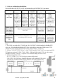
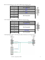
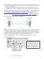
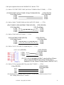
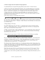
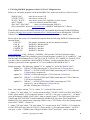
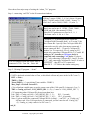
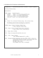
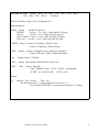
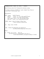
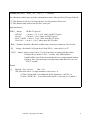
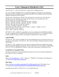
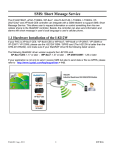
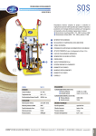
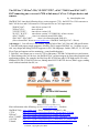
The WP-8xx7, XP-8xx7-CE6, VP-25W7/23W7 , uPAC-7186EG and iPAC-8447 /
8847 connecting one or several i-7530 to link many CAN or CANopen devices and
sensors .
by [email protected]
ISaGRAF PAC since their following driver version support i-7530 - the RS-232 to CAN converter to
link CAN devices and CAN sensors or CAN open devices or CAN open sensors.
WinPAC-8xx7 :
since driver version 1.02.
XP-8xx7-CE6 :
since released.
VP-25W7/23W7 :
since driver version 1.02.
W-8347 / W-8747 :
since driver version 3.43 (2008.Feb), or later version.
uPAC-7186EG :
since it is released (around 2008. Mar).
iPAC-8447 / iPAC-8847 :
since it is released (around 2009.Q1).
(New released PAC driver at www.icpdas.com > ISaGRAF SoftLogic PAC > Driver)
Advantages: 1. Cost effective CAN solution, supports both of the CAN 2.0A and 2.0B specifications.
2. Provided with proper sample programs. All above PACs support ISaGRAF ver. 3 software to easy
edit, easy design and debug (ISaGAF supports six PLC-like languages: Ladder, FBD, ST, IL, SFC and
Flow Chart and supports on-line monitoring , control and debugging)
3. Each PAC can connect one or several i-7530 to link many CAN and CANopen devices and sensors.
4. When linking with CAN devices, the ISaGRAF PAC can also integrate its some other functions and
applications together. For example, the Hot-Swap RU-87P4/8 base plus I-87K high-profile I/O cards ,
Modbus RTU (RS-232/485/422) devices, linking other RS-232/485/422 devices, Data Logger, sending
email with one attached data file, etc.
More information at the following, or visit www.icpdas.com > Products
ISaGRAF FAQ : www.icpdas.com > FAQ > Software > ISaGRAF > 086
i-7530 :
http://www.icpdas.com/products/Remote_IO/can_bus/i-7530.htm
WP-8xx7 :
http://www.icpdas.com/products/PAC/winpac/wp-8x47.html
uPAC-7186EG : http://www.icpdas.com/products/PAC/i-7188_7186/uPAC-7186eg.htm
i-8112iW :
http://www.icpdas.com/products/PAC/i-8000/8000_IO_modules.htm
X board :
http://www.icpdas.com/products/PAC/i-o_expansion/x_list.htm
Feb.2008 , Copyright by ICP DAS
1
1.1: Software and hardware installation :
Below table shows the RS-232 port No. and amount that each ISaGRAF PAC can connect.
W-8xx7
RS-232 Port
No
can be used
COM1 or
COM2 or
COM3
~ 14
COM5 ~
(COM5
~ 14
COM14
resides at
(COM5 ~ 14
i-8112iW
or
resides at i8112 / i-8114 i-8114iW :
: the RS-232 the RS-232
expansion
expansion
card
in slot 0
card in slot 1
thru. 5)
Max. i-7530
that one PAC
can connect
(one i-7530 for
each RS-232)
Recommended
max. amount of
CAN devices
linked by one i7530
WP-8xx7
thru. 3)
VP-25W7
VP-23W7
COM3 or
COM5 ~ 14
(COM5 ~ 14
resides at
i-8112iW or
i-8114iW :
the RS-232
expansion
card in slot 0
uPAC-7186EG
iP-8xx7
COM1 or
COM3 ~ COM8
COM1 or
COM3 ~
COM12
(COM5 ~
COM12 resides
at i-8112 / i-8114
: the RS-232
expansion card
in
(COM3 ~ COM8
resides at X-5xx :
RS-232
expansion card in
the X-socket, like
the X-503, 504,
505, 506, 508)
thru. 2)
Max. 10 ports to connect max.
ten i-7530
slot 0 and 1)
Max. 3 ports to
connect max.
Max. 3 ports to
connect max.
three i-7530
three i-7530
60 pcs.
30 pcs.
30 pcs.
(the more devices connected, the slower scan
rate and longer PLC scan time)
(the more devices
connected, the
slower scan rate
and longer PLC
scan time)
(the more devices
connected, the
slower scan rate
and longer PLC
scan time)
Note:
1. The COM1 port of the uPAC-7186EG and iPAC-8447/8847 is default enabled as Modbus RTU
slave port. Please disable this Modbus RTU slave setting before connecting COM1 to one i-7530.
(Please refer to the Getting Started manual of the uPAC-7186EG – section 3.6)
2. WP-8xx7, VP-25W7/23W7, W-8xx7 , uPAC-7186EG and iPAC-8447 / 8847 can support only RS232 baud-rate setting of 115200 , 57600 , 38400 , 19200 and 9600 to link i-7530, the other setting
should be No Parity , 8 bit size , 1 stop bit . The Checksum setting can be No or Yes.
3. Default setting of the i-7530:
RS-232 : 115200, N, 8, 1, No Checksum (recommended setting)
CAN: 125K , 2.0A CAN spec. (should be the same as all connected CAN device)
Built-in one CAN BUS terminal resistor, default is ON (with 120 Ω, by JP3)
(ISO 118982 spec. : two terminal 120 Ω resistors in one CAN BUS network)
Feb.2008 , Copyright by ICP DAS
2
RS-232 Pin-assignment of i-7530: RS-232 DB9 Female Connector (CN1)
Terminal
1
2
3
4
5
6
7
8
9
3-wire RS-232
Not Connected
TXD
RXD
Not Connected
GND
Not Connected
CAN Pin-assignment of i-7530: CAN DB9 Male Connector (CN2)
Terminal
1
2
3
4
5
6
7
8
9
2-wire CAN
Not Connected
CAN Low
Not Connected
CAN High
Not Connected
Connecting diagram of the i-7530 CAN port to other CAN devices or CANopen devices:
Feb.2008 , Copyright by ICP DAS
3
Before ISaGRAF PAC connecting i-7530 to link to CAN device, please make sure following items.
(1) CAN port setting should be the same as all connected CAN devices (default setting of the i-7530
is 125K , CAN 2.0A).
(2) RS-232 port setting of the i-7530 should be the same as the connected ISaGRAF PAC (The
default setting is “115200, 8, N, 1 and No checksum” for both. Recommend to use it directly).
To modify the CAN or RS-232 port setting of the i-7530, please run the “i7530.exe” software tools in
PC. This software tools can be found in the CD-ROM delivered with the i-7530. Or please visit
ftp://ftp.icpdas.com/pub/cd/fieldbus_cd/can/converter/i-7530/utility/ to download it.
For more information about i-7530, please refer to its user’s manual “i-7530.pdf” . It resides at the
same CD-ROM or visit ftp://ftp.icpdas.com/pub/cd/fieldbus_cd/can/converter/i-7530/manual/ .
RS-232 connection diagram between the i-7530 and PC.
Note:
1. There is one Dip switch on the back of i-7530. To properly run “i7530.exe” to modify the setting of
i-7530, please (1) Shut down i-7530 ‘s 24V power (2) Turn Dip switch to “Init” position (3) Power on
i-7530 again. Then this “i7530.exe” is possible to modify the RS-232 and CAN port setting. Please
remember to turn this “Dip” switch back to “Normal” position and then reset i-7530 power once. Or it
will not work ( i-7530 can only link CAN / CANopen devices in “Normal” mode).
2. More detail about using the “i7530.exe” and command format, please refer to “i-7530.pdf” .
View of operating “i7530.exe” :
i-7530 should be in “INIT” mode
to modify its RS-232 and CAN
port setting. Remember to switch
the “Dip” back to “Normal”
mode, or it will not work with
other CAN / CANopen devices.
Feb.2008 , Copyright by ICP DAS
4
Cable pin-assignment between the ISaGRAF PAC and the i-7530.
(1) Cable of VP-25W7/23W7 COM3 ( & W-8xx7 COM2 & iP-8xx7 COM4) --- i-7530 :
VP-25W7 COM3 / W-8xx7 COM2 / iP-8xx7 COM4 (RS-232)
9-Pin Dsub Female
2 RXD
3 TXD
5 GND
i-7530 (RS-232)
9-Pin Dsub Male
2 TXD
3 RXD
5 GND
(2) Cable of uPAC-7186EG COM1 (& iPAC-8447/8747 COM1) --- i-7530 :
uPAC-7186EG / iPAC-8447/8847 COM1 (RS-232) i-7530 (RS-232)
9-Pin Dsub Male
9-Pin Dsub Male
2 TXD
2 TXD
3 RXD
3 RXD
5 GND
5 GND
(3) Cable of iPAC-8447/8747 COM3 --- i-7530 :
iPAC-8447/8847 COM3 (RS-232)
9-Pin Dsub Female
2 TXD
3 RXD
5 GND
i-7530 (RS-232)
9-Pin Dsub Male
2 TXD
3 RXD
5 GND
(4) Cable of i-8112 / 8114 RS-232 expansion port --- i-7530 :
i-8112 / 8114 (RS-232)
5 TXD
6 RXD
7 GND
i-7530 (RS-232)
9-Pin Dsub Male
2 TXD
3 RXD
5 GND
(If i-8112 / 8114 is plugged in W-8xx7, user should run Wincon
utility to setup the RS-232 ports once. Please refer to
Appendix E of the “Wincon Getting Started: ISaGRAF PAC”)
(5) Cable of X-5xx expansion RS-232 port in uPAC-7186EG --- i-7530 :
X-5xx (RS-232)
i-7530 (RS-232)
9-Pin Dsub Male
RXD
2 TXD
TXD
3 RXD
GND
5 GND
(For detailed pin-assignment of the X-5xx RS-232 ports, please refer to section 3.14 of
the “Getting started: uPAC-7186EG)
Feb.2008 , Copyright by ICP DAS
5
(6) Cable of WinPAC-8147/8447/8447 --- i-7530
Note: The WP-8147 doesn't have COM3 and COM4. The WP-8447/8847 have them.
WinPAC COM1 (RS-232)
9-Pin Dsub Male
2 TXD
3 RXD
5 GND
i-7530 (RS-232)
9-Pin Dsub Male
2 TXD
3 RXD
5 GND
WinPAC COM3 (RS-232)
9-Pin Dsub Female
2 TXD
3 RXD
5 GND
i-7530 (RS-232)
9-Pin Dsub Male
2 TXD
3 RXD
5 GND
WinPAC COM4 (RS-232)
9-Pin Dsub Female
2 RXD
3 TXD
5 GND
i-7530 (RS-232)
9-Pin Dsub Male
2 TXD
3 RXD
5 GND
Please refer to Appendix E of the WinPAC ISaGRAF Getting Started Manual for using
WP-8xx7 's or VP-25W7/23W7 COM5 to COM14 in i-8112iW / i-8114iW / i-8114W.
(The complete manual resides at
WinPAC-8xx7 CD-ROM:\napdos\isagraf\wp-8xx7\english_manu\)
WinPAC / VP-25W7 / VP-23W7 COM5~14 (RS-232)
RXD
TXD
GND
Feb.2008 , Copyright by ICP DAS
i-7530 (RS-232)
9-Pin Dsub Male
2 TXD
3 RXD
5 GND
6
1.2: Basic concepts of the CAN and the CANopen protocols.
To understand the basic concepts before going further into the section 1.3 is better for users.
CAN bus is one of the serial communication interfaces. For easy understanding, here we can image
that CAN is similar to the RS-485 interface, but the physical hardware and algorithm is different as
RS-485. CAN bus has two branches, one is CANopen , the other is DeviceNet. Then we know
CANopen fits the spec. of CAN bus. For easy understanding, user can image that CANopen is
something similar to the RS-485 Modbus RTU protocol. It is not really a good example, but a better
image for you to know about them.
Each CAN bus package (or called frame) shows as below.
ID
RTR
DLC
Data field. Max. 8 bytes (only for “Standard frame”)
The “ID” field is an identification number of the CAN frame. If it is a CAN 2.0A frame, the ID field
has 11 bits. So its value can be 0 ~ 7FF (Hex.) . While 29 bits for CAN 2.0B frame, so its value can be
0 to 1FFFFFFF (Hex.).
CANopen belongs to 2.0A Sepc.
The “RTR” field has only 1 bit. If its value is 1, it means the frame is using as “Remote-transmit
requests”, or called “Remote frame” . It is for requesting the other CAN device to send proper data
back. There is no Data field for “Remote frame” .
If “RTR” is 0, then the frame is called “Standard frame” . It is for sending data to other CAN devices.
So “Standard frame” must have Data field . The “DLC” indicates the byte amount of the following
Data field. Its value can be 0 to 8.
CANopen frame has same format as CAN bus. However it divides the ID filed into 2 sub-fields.
Function Code, 4 bits
Node ID, 7 bits
Bit 1 to 7 indicates the CANopen “Node-ID” (or called CANopen “Station No.”). This value can be 1
to 7F (Hex. , its decimal value is 1 to 127 )., Value 0 has special usage. (For example, to switch one
CANopen device to be in “operational state” is using “Node ID” as 0) . So here we know, one
CANopen network can connect max. 127 CANopen devices.
The “Function Code” field has 4 bits (bit 8 to 11). It defines the function of the CANopen frame. For
example, some function code is for requesting Application Data , some is for sending Application Data
to others. We will not talking more about the CAN and CANopen protocols, please refer to the user’s
manual of each 3rd party CAN products.
Note: Please don’t mix CAN devices and CANopen devices in the same CAN bus network. That is
because the CAN ID field may conflict with each other. If all devices in the same CAN bus are all
CANopen devices, there will be no problem if they has different CANopen Node ID number (can be 1
to 127) .
Feb.2008 , Copyright by ICP DAS
7
1.3: Writing ISaGRAF programs to link to CAN or CANopen devices
Before you can run the program well in the ISaGRAF PAC, make sure its driver version is correct.
WinPAC-8xx7 :
since driver version 1.02.
VP-25W7/23W7 :
since driver version 1.02.
W-8347 / W-8747 :
since driver version 3.43 (2008.Feb), or later version.
uPAC-7186EG :
since it is released (around 2008. Mar).
iPAC-8447 / iPAC-8847 :
since it is released (around 2009.Q1).
(New released PAC driver at www.icpdas.com > ISaGRAF SoftLogic PAC > Driver)
Then also make sure your ISaGRAF software in PC has installed the following ISaGRAF IO library.
You may visit http://www.icpdas.com/products/PAC/i-8000/isagraf.htm to download the “ICP DAS
Utilities For ISaGRAF” . Then run “setup.exe” to remove it first and then re-install it once.
Please refer to the section 1.4 for detailed description about the following ISaGRAF c-functions and cfunction blocks.
CAN7530 :
I/O complex equipment (in the IO connection window)
CAN_R:
ISaGRAF C function-block
CAN_BY_W:
ISaGRAF C function
CANSTR_W:
ISaGRAF C function
CANOP_ST:
ISaGRAF C function
www.icpdas.com > FAQ > Software > ISaGRAF > 086 provides CAN and CANopen sample
programs and document. They should be at least 5 demo programs “wpdmo71a” to “wpdmo71e” . And
also the single IO definition file of CAN7530, CAN_R, CAN_BY_W, CANSTR_W, CANOP_ST (If
you don’t want to re-install the whole ISaGRAF IO library, you may install the above 5 items
separately, please refer to the Appendix A.2 of “user’s manual of the ISaGRAF PAC” ).
Sample programs: (The following “wpdmo71a” to “wpdmo71e” are for the WinPAC-8xx7)
wpdmo71a : WP-8xx7 COM4 connecting one i-7530 to link one CANopen device.
wpdmo71b : WP-8xx7 + i-8112iW (COM5 and COM6) connecting one i-7530 to link one
CANopen device respectively.
wpdmo71c : WP-8xx7 COM4 connecting one i-7530 to link one CAN device.
wpdmo71d : WP-8xx7 + i-8112iW (COM5 and COM6) connecting one i-7530 to link one
CAN device respectively.
wpdmo71e : WP-8xx7 + i-8112iW (COM5 and COM6) connecting one i-7530
respectively , one is linking one CANopen device,
the other is linking one CAN device.
Note: (the sample “wdemo_71a” to “wdmo_71e” are for the Wincon-8xx7)
1. “wdmo_71a” and “wdmo_71c” can also run in the uPAC-7186EG’s COM1 or in iPAC-8447/8847’s
COM1, please modify (1) IO connection window > can7530 > com_port ‘s value to be 1 , (2) Initial
value of the Integer variable “Port2” to be 1, then re-compile it once. (The COM1 port of the uPAC7186EG and iPAC-8447/8847 is default enabled as Modbus RTU slave port. Please disable this
Modbus RTU slave setting before connecting COM1 to one i-7530. Please refer to the Getting manual
of the uPAC-7186EG – section 3.6)
2. “wdmo_71b” and “wdmo_71d” and “wdmo_71e” can also run in uPAC-7186EG + X-5xx board or
in iPAC-8447/8847 (may plus i-8112/8114) , please modify (1) IO connection window > can7530 >
com_port ‘s value , (2)Initial value of Integer variables “Port5” and “Port6” , then re-compile it.
Feb.2008 , Copyright by ICP DAS
8
Here shows four major steps of writing the “wdmo_71a” programs.
Step 1 : connecting “can7530” in the IO connection windows.
WP-8xx7 can use COM1, 3, 4, 5 to 14 (max. 10 ports)
uPAC-7186EG can be COM1, COM3 ~ 8 (max. 3)
iPAC-8xx7 can be COM1, COM3 ~ 12 (max. 3)
Baud_rate can be one of 115200 , 57600 , 38400 ,
19200 and 9600. (Recommend 115200)
Other RS-232 parameters are fixed as 8 , 0 , 1
Checksum can be 0: No or 1:Yes
This D/I channel returns the comm. state of
connected i-7530 . True: Ok , False: fail.
CANopen_01_32 should specify the connected
CANopen Node ID number from 1 to 32, using 32-bit
Hex. format. Bit 1 specify if the CAN open Node ID 1
connected or not, bit value 0 means not connected, 1
means connected. Bit 2 ~ 32 specify CANopen ID
number 2 to 32 respectively. For ex, setting as “F0”
means only connecting CANopen ID No. 5,6,7 and 8. If
setting as “0”, it means no CANopen device is
connected, only connecting CAN device. If value is
“1C” , only connecting CANopen ID 3,4 and 5. If value
is “3” , only connecting CANopen ID 1 and 2. If value is
“FFFFFFFF” , then ID 1 to 32 is connected.
Other ID 33 ~ 127 follows the similar setting way.
Step 2 : Writting ST program – “Scan1”
if INIT then
(* INIT is declared as initial value at True, so this block will run only once in the 1st PLC scan *)
INIT := False ;
TMR2 := T#0s ;
Tstart(TMR2) ; (* start ticking Timer variable - TMR2 *)
Max_Step2 := Period2 / Interval2 ;
(* Set a Boolean variable name to get the comm. state of the CAN open ID 1, timeout is 5 sec *)
TMP := CanOp_st( Port2 , CAN_OPEN2_ID1 , 1 , 5 ) ; (* name is “CAN_OPEN2_ID1” *)
(* If connecting other CANopen ID, please insert them here.
Like TMP := CanOp_st( Port2 , CAN_OPEN2_ID2 , 2 , 5 ) ;
ID 2 , 5 seconds
Like TMP := CanOp_st( Port2 , CAN_OPEN2_ID3 , 3 , 10 ) ; ID 3 , 10 seconds
Note: (1) please enable the connected CANopen ID No. in Step1 – “can7530” , or ”CanOp_st( )”
will not work. If no CAN open device is connected, you don’t need to call “CanOp_st( )”
(2) “CanOp_st( ) only works in 1st PLC scan *)
end_if ;
Feb.2008 , Copyright by ICP DAS
9
Step 3 : Writing ST program – “Can2_r” (handle coming frames from the connected i-7530)
num_frame := 0 ; (* reset as 0 at the beginning *)
While num_frame < 10 Do (* max. run only 10 loops to avoid scan time increasing a lot *)
(* test if any CAN frame coming, here “CanR” is declared as a “FB instance” of “CAN_R” *)
CanR(Port2) ;
(* if True, means CAN frame is coming. if it is False, the following value has no meaning *)
Can_Coming := CanR.Q_ ;
If Can_Coming = False then
return ; (* no CAN frame, exit this ST program to run next program *)
end_if ;
Can_Mode := CanR.MODE_ ; (* CAN frame ‘s MODE value, 0 : 2.0A or 1 : 2.0B *)
Can_RTR := CanR.RTR_ ; (* CAN frame ‘s RTR value, 0: Standard frame or 1: remote *)
Can_ID := CanR.ID_ ;
(* CAN frame’s ID value *)
Can_DLC := CanR.DLC_ ; (* CAN frame ‘s data byte amount , 0 ~ 8 *)
Can_By1 := CanR.BY1_ ; (* Data field, max. 8 Bytes *)
Can_By2 := CanR.BY2_ ;
Can_By3 := CanR.BY3_ ;
Can_By4 := CanR.BY4_ ;
Can_By5 := CanR.BY5_ ;
Can_By6 := CanR.BY6_ ;
Can_By7 := CanR.BY7_ ;
Can_By8 := CanR.BY8_ ;
Can_str := CanR.MSG_ ; (* Data filed in string format *)
num_frame := num_frame + 1 ; (* frame is coming, plus 1 *)
if Can_Mode = 0 then (* if the coming frame is “CAN 2.0A” frame *)
if Can_RTR = 0 then (* if it is “Standard” frame *)
Case Can_ID Of
16#181 : (* D/I : Function code 16#180 + CAN OPEN ID 1 = 16#181 *)
If Can_DLC > 0 then
(* data byte amount must > 0 *)
DI_01 := Byte_Bit( Can_By1, 1) ; (* get D/I value of Ch.1 *)
DI_02 := Byte_Bit( Can_By1, 2) ;
DI_03 := Byte_Bit( Can_By1, 3) ;
DI_04 := Byte_Bit( Can_By1, 4) ;
DI_05 := Byte_Bit( Can_By1, 5) ;
DI_06 := Byte_Bit( Can_By1, 6) ;
DI_07 := Byte_Bit( Can_By1, 7) ;
DI_08 := Byte_Bit( Can_By1, 8) ; (* Ch.8 *)
End_if ;
Feb.2008 , Copyright by ICP DAS
1
16#281 : (* A/I: Function code 16#280 + CAN OPEN ID 1 = 16#281 *)
If Can_DLC >= 8 then (* here assumes 16#281 frame contains 4 Ch. of A/I *)
AI_01 := Byte_sWD( Can_By1 , Can_By2 ) ; (* each A/I has 2 bytes *)
AI_02 := Byte_sWD( Can_By3 , Can_By4 ) ; (* LoByte , HiByte *)
AI_03 := Byte_sWD( Can_By5 , Can_By6 ) ;
AI_04 := Byte_sWD( Can_By7 , Can_By8 ) ;
End_if ;
16#381 : (* A/I 資料: Function code 16#380 + CAN OPEN ID 1 = 16#381 *)
If Can_DLC >= 8 then (*here assumes 16#381 frame contains 4 Ch. of A/I *)
AI_05 := Byte_sWD( Can_By1 , Can_By2 ) ; (* each A/I has 2 bytes *)
AI_06 := Byte_sWD( Can_By3 , Can_By4 ) ; (* LoByte , HiByte *)
AI_07 := Byte_sWD( Can_By5 , Can_By6 ) ;
AI_08 := Byte_sWD( Can_By7 , Can_By8 ) ;
End_if ;
(* If there is other CANopen ID frames, please insert them here.
For example, Function code 16#280 + CAN OPEN ID 2 = 16#282 *)
(*
16#282 :
If Can_DLC >= 4 then
AI_09 := Byte_sWD( Can_By1 , Can_By2 ) ;
AI_10 := Byte_sWD( Can_By3 , Can_By4 ) ;
End_if ;
*)
End_case ;
Else (* Can_RTR = 1 : the coming CAN frame is “Remote” frame *)
end_if ;
else (* Can_Mode=1 : the coming frame is “CAN 2.0B” frame *)
end_if ;
End_While ;
Feb.2008 , Copyright by ICP DAS
1
Step 4 : Writing ST program – “Can2_W” (handle sending frames to the i-7530)
(* wdmo_71a defines Period2 = 200 (ms) , Interval2 = 20 (ms). It means one period time is 0.2 sec.
max. (200 / 20) - 1 = 9 frames can be sent in one period, frame interval is 0.02 second.
Step2=1 (at 0 ms) : send Remote frame with ID=16#181 to request CANopen 1 to send back D/I
Step2=2 (at 20 ms) : send Remote frame with ID=16#281 to request CANopen 1 to send back A/I
Step2=3 (at 40 ms) : send Remote frame with ID=6#381 to request CANopen 1 to send back A/I
Step2=4 (at 60 ms) : send Standard frame with ID=16#201 to CANopen 1 to control D/O
Step2=5 (at 80 ms) : send Standard frame with ID=16#301 to CANopen 1 to control A/O
Step2 = 0, 6 ~ 10 : (at between 80 ms to 200 ms) : send nothing
Step2 can only be max. at 9 in this sample program, if user need larger value to send more frames,
please modify the initial value of Period2 and Interval2 and then re-compile it.
Interval2 should be larger than or equal to 10 (ms) , 0 or negative value will crush this program.
Period2 should be at least twice of Interval2 value, and should be larger than or equal to 100 (ms) *)
TMR2_val := ANA( TMR2 ) ; (* convert Timer to become Integer value, unit is ms *)
TMR2_val := MOD( TMR2_val , Period2 ) ; (* get rest value *)
Send2 := False ; (* reset as False: no requesting to send any frame *)
(* here divided as 200/20 = 10 Steps. Interval is 20 ms *)
(* value of Max_Step2 is calculated in 1st scan in “Scan1” program. Its value is 200/20 = 10 *)
if Step2 >= 0 and Step2 <= Max_Step2-1 then
if TMR2_val >= Interval2 * Step2 then
Step2 := Step2 + 1 ;
Send2 := True ; (* reach time point of each step, set as True to request to send 1 frame *)
end_if ;
else (* value of Step reach maximum step value *)
if TMR2 >= TMR(Period2) then (* If the time is over one Period *)
Step2 := 0 ;
(* reset Step as 0 *)
TMR2 := T#0s ; (* reset Timer as 0 *)
end_if ;
end_if ;
(* The following code is for sending frame at each Step2 value *)
If Send2 then
Send2 := False ; (* reset as False *)
CASE Step2 Of
0:
(* Step is 0: DO NOT send any frame at Step = 0 *)
Feb.2008 , Copyright by ICP DAS
1
1 : (* Step is 1: sending Remote frame to request CAN open ID 1 ‘s D/I , request 1 byte *)
TMP := CAN_BY_W( Port2 , 0 , 1 , 16#181 , 1 , 0,0,0,0, 0,0,0,0 ) ;
2 : (* Step is 2: sending Remote frame to request CAN open ID 1 ‘s A/I, request 8 bytes *)
TMP := CAN_BY_W( Port2 , 0 , 1 , 16#281 , 8 , 0,0,0,0, 0,0,0,0 ) ;
3 : (* Step is 3: sending Remote frame to request CAN open ID 1 ‘s A/I, request 8 bytes *)
TMP := CAN_BY_W( Port2 , 0 , 1 , 16#381 , 8 , 0,0,0,0, 0,0,0,0 ) ;
4 : (* Step is 4: sending Standard frame to CAN open ID 1 to control D/O, send 1 byte *)
(* convert 8 Boolean values to become 1 byte value *)
Tmp_val := Bit_WD( DO_01, DO_02, DO_03, DO_04, DO_05, DO_06, DO_07,
DO_08, False, False, False, False, False, False, False, False ) ;
(* then send it *)
TMP := CAN_BY_W( Port2 , 0 , 0 , 16#201 , 1 , Tmp_val , 0,0,0, 0,0,0,0 ) ;
5 : (* Step is 5: sending Standard frame to CAN open ID 1 to control A/O, send 8 bytes *)
TMP := CAN_BY_W( Port2 , 0 , 0 , 16#301 , 8 ,
MOD(AO_01,256) , AO_01/256 , (* Lo_byte , Hi_byte *)
MOD(AO_02,256) , AO_02/256 ,
MOD(AO_03,256) , AO_03/256 ,
MOD(AO_04,256) , AO_04/256 ) ;
(* it there is other frames to send, please insert them here.
Step2 can only be max. at 9 in this sample program, if user need larger value to send more
frames, please modify the initial value of Period2 and Interval2 and then re-compile it.
Interval should be larger than or equal to 10 (ms) , 0 or negative value will crush this program.
Period2 should be at least twice of Interval value, and should be larger than or equal to 100 (ms) *)
(* below shows requesting CAN open ID 2 ‘s A/I data, request 4 bytes
6:
TMP := CAN_BY_W( Port2 , 0 , 1 , 16#282 , 4 , 0,0,0,0, 0,0,0,0 ) ;
*)
(* this sample program defines (Period2 , Interval2) as (200, 20) , so max. step can be used is
Only (200/20)-1= 9 *)
End_case ;
End_if ;
For description of other sample programs – “wdmo_71b” to “wdmo_71e”, please refer to section 9.5 of
the “User’s manual of the ISaGRAF PAC” to restore them into ISaGRAF workbench first. Then open
each sample programs, you will find detailed comments in each ST programs.
Feb.2008 , Copyright by ICP DAS
1
1.4: Definitions of the CAN functions and function-blocks
CAN_R( PORT_ ) : c-function block (please declare “FB instance” if using in ST programs )
Test if any CAN frame coming
Input parameters:
PORT_ Integer
The RS-232 port No.
WP-8xx7 :
Can be 1 , 3, 4 , 5 to 14 (Max. ten RS-232 ports)
W-8xx7 :
Can be 2 , 5 to 14 (Max. ten RS-232 ports)
uPAC-7186EG: Can be 1 , 3 to 8 (Max. three RS-232 ports)
iPAC-8xx7: Can be 1 , 3 to 12 (Max. three RS-232 ports)
Return :
Q_
Boolean True : at least one CAN frame coming . False : no frame coming.
The following return value has no meaning if Q_ returns False.
MODE_ Integer 0: frame is 2.0A frame , (ID has 11 bits)
1: frame is 2.0B frame , (ID has 29 bits)
RTR_
ID_
DLC_
Integer 0: frame is “Standard” frame (with 0 to 8 data bytes)
1: frame is “Remote” frame, (without data byte)
Integer frame ‘s ID field .
Integer byte amount of the data filed, can be 0 to 8 .
BY1_ ~ BY8_ Integer Byte data.
(only ”Standard” frame has BY1_ to BY8_ )
MSG_
Message byte data in string format. Note, if any of BY1_ to BY8_ ‘s value is 0, it
will become the string end. For example, if receiving one frame with 8
data bytes in hex. is 41 , 42 , 43 , 4A , 0 , 4B , 4C , 4D ,
then MSG_ will be 'ABCJ'
(only ”Standard” frame ‘s MSG_ is meaningful)
Feb.2008 , Copyright by ICP DAS
1
CAN_BY_W( PORT_ , MODE_ , RTR_ , ID_ , DLC_ , BY1_ , BY2_ , BY3_ , BY4_ ,
BY5_ , BY6_ , BY7_ , BY8 ) : c-function
Send CAN frame to other CAN / CANopen devices
Input parameters:
PORT_ Integer
The RS-232 port No.
WP-8xx7 :
Can be 1 , 3, 4 , 5 to 14 (Max. ten RS-232 ports)
W-8xx7 :
Can be 2 , 5 to 14 (Max. ten RS-232 ports)
uPAC-7186EG: Can be 1 , 3 to 8 (Max. three RS-232 ports)
iPAC-8xx7: Can be 1 , 3 to 12 (Max. three RS-232 ports)
MODE_ Integer 0: frame is 2.0A frame , (ID has 11 bits)
1: frame is 2.0B frame , (ID has 29 bits)
RTR_
Integer 0: frame is “Standard” frame (with 0 to 8 data bytes)
1: frame is “Remote” frame, (without data bytes)
ID_
Integer frame ‘s ID field .
DLC_ Integer byte amount of the data filed, can be 0 to 8 .
BY1_ ~ BY8_ Integer Byte data.
(only ”Standard” frame ‘s BY1_ to BY8_ is meaningful.
If RTR_ is 1, please set BY1_ to BY8_ to 0)
Return:
Q_
Boolean True : succeed .
False : fail.
(the fail reason can be (1) input parameter is not correct, or
(2) the related CAN PORT_ is not open successfully or (3) others)
Feb.2008 , Copyright by ICP DAS
1
CANSTR_W( PORT_ , MODE_ , ID_ , MSG_ ) : c-function
Send CAN frame to other CAN / CANopen device (the data is a string)
*** All frames sending by “CANSTR_W( )” must be “Standard” frame. Please use
“CAN_BY_W( )” to send “Remote” frame.
Input parameters:
PORT_ Integer
The RS-232 port No.
WP-8xx7 :
Can be 1 , 3, 4 , 5 to 14 (Max. ten RS-232 ports)
W-8xx7 :
Can be 2 , 5 to 14 (Max. ten RS-232 ports)
uPAC-7186EG: Can be 1 , 3 to 8 (Max. three RS-232 ports)
iPAC-8xx7: Can be 1 , 3 to 12 (Max. three RS-232 ports)
MODE_ Integer 0: frame is 2.0A frame , (ID has 11 bits)
1: frame is 2.0B frame , (ID has 29 bits)
ID_
Integer frame ‘s ID field .
MSG_ Message the sending string, max. length is 8 byte .
(the 9th byte and other higher bytes will be useless )
Return:
Q_
Boolean True : succeed .
False : fail.
(the fail reason can be (1) input parameter is not correct, or
(2) the related CAN PORT_ is not open successfully or (3) others)
Feb.2008 , Copyright by ICP DAS
1
CANOP_ST( PORT_ , BOO_ , ID_ , TOUT_ ) : c-function
Set a Boolean variable name to get the communication state of the specified CAN open Node ID.
*** This function is only for CAN open devices , not for general CAN devices.
*** This function only works in the first PLC scan cycle.
Input parameters:
PORT_ Integer
The RS-232 port No.
WP-8xx7 :
Can be 1 , 3, 4 , 5 to 14 (Max. ten RS-232 ports)
W-8xx7 :
Can be 2 , 5 to 14 (Max. ten RS-232 ports)
uPAC-7186EG: Can be 1 , 3 to 8 (Max. three RS-232 ports)
iPAC-8xx7: Can be 1 , 3 to 12 (Max. three RS-232 ports)
BOO_ Boolean should be a Boolean variable name, can not use constant or True or False
ID_
Integer the related CAN open device Node ID No. , value can be 1 to 127 .
TOUT_ Integer unit is second. Can be 3 to 120. If no frame is coming from the related
CANopen device in this “TOUT_” seconds, value of the Boolean
Variable will be set as False (It means that device is communication broken).
If value is True, it means always receiving frames from that device in every
“TOUT” seconds.
Return:
Q_
Boolean True : succeed .
False : fail.
(The fail reason can be (1) input parameter is not correct, or
(2) This CANopen ID is not enabled in the IO connection > can7530, or
(3) this CANOP_ST( ) is not called in the first PLC scan cycle or (4) others )
Feb.2008 , Copyright by ICP DAS
1