1
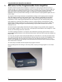
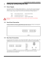
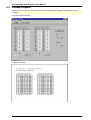
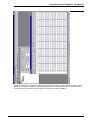
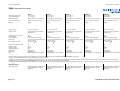
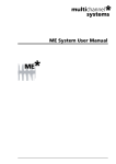
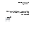
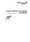
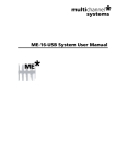
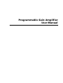
Programmable Gain Amplifier
User Manual
Information in this document is subject to change without notice.
No part of this document may be reproduced or transmitted without the express written
permission of Multi Channel Systems MCS GmbH.
While every precaution has been taken in the preparation of this document, the publisher and the
author assume no responsibility for errors or omissions, or for damages resulting from the use of
information contained in this document or from the use of programs and source code that may
accompany it. In no event shall the publisher and the author be liable for any loss of profit or any
other commercial damage caused or alleged to have been caused directly or indirectly by this
document.
© 2001-2005 Multi Channel Systems MCS GmbH. All rights reserved.
Printed: 2005-01-31
Multi Channel Systems
MCS GmbH
Aspenhaustraße 21
72770 Reutlingen
Germany
Fon
+49-71 21-90 92 5 - 0
Fax
+49-71 21-90 92 5 -11
[email protected]
www.multichannelsystems.com
Microsoft and Windows are registered trademarks of Microsoft Corporation. Products that are
referred to in this document may be either trademarks and/or registered trademarks of their
respective holders and should be noted as such. The publisher and the author make no claim to
these trademarks.
Table of Contents
1
Welcome to the Programmable Gain Amplifier
2
2
Setting Up and Operating the PGA
3
2.1
Power Supply
3
2.2
Front Panel Connection
3
2.3
Rear Panel Connection
3
2.4
FiltAmp Program
4
3
Technical Specifications
6
4
Connectors — Pin Layout
7
4.1
Input Connector
7
4.2
Output Connector
7
Programmable Gain Amplifier User Manual
1
Welcome to the Programmable Gain Amplifier
The Multi Channel Systems device PGA64 is an amplifier of analog signals with the option to
change the gain. The input signal amplitude can be increased from a factor of 10 up to 5000. The
gain is selectable by software and can be set for each of the 64 signal channels individually. The
main parts consist of the analog filter stages, of a logic part to set the amplification, of an
EEPROM to save the potentiometer settings, of a level converter accepting RS232 signals and of a
power stage.
The signals of the 64 input channels are amplified according to the frequency band. The band
filter the signals according to the frequency parts. The outputs are observable on the output
connector. Examples of output signals are given. A figure in the appendix demonstrates the
dependance of the output signal amplitude from the frequency for the used frequency band.
Input signals are connected using a 68-pin connector. Output signals are transferred to other
devices using a 68-pin connector, too. The pin layout of both connectors is given in a table. The
digital signals to change the gain are delivered using a 9-pin SUB-D connector via the serial
interface of a PC.
An internal power supply stage transforms the input voltages of any external power supply bin
into the supply voltages of ±3.0 V and ±5.0 V. The supply bin should deliver raw voltages of ± 6.0 V
at least, for connecting use 4 mm-connectors.
A software package installed on a computer with a Windows operating system makes it easy to
set the digital potentiometers to the selected values. Note: check the serial connection using a test
button first.
In a next step, the gain can be selected individually for each channel. Or use the pull-down menu
for a general setting. Push the download button and the values are written to an EEPROM in the
PGA64. Automatically, the new values are written into the digital potentiometers, too. If you
switch off the PGA64, the last setting of the potentiometers are stored. After switching on again,
these values will be restored.
An online Help is available and will explain the program functions.
During loading down the settings to the PGA, please, stop any running program or set to sleep
mode!
2
Programmable Gain Amplifier User Manual
2
Setting Up and Operating the PGA
2.1
Power Supply
The recommended value of supply voltage should be US = ± 6.0 V. The limits of proper operation
ranges from ± 5.7 V to ± 12.0 V. Please, be careful. Use the lowest voltage as possible. As higher
the input supply voltage, as higher the internal heat produced by the voltage regulators!
+6.0 V:
GND:
–6.0 V:
4 mm red plug connector
positive supply voltage
4 mm black plug connector
ground
4 mm blue plug connector
negative supply voltage
Warning: Do not mismatch the polarity of the power supply. False connection may damage
the device.
2.2
Front Panel Connection
The only connection on the front of the PGA64 is the connector for in-coupling the analog signals.
The input connector has to be plugged into the 68-pin front connector.
2.3
Rear Panel Connection
The output signal cable (OUTPUT), the download cable (SERIAL COM), and the power supply cable
(POWER), have to be connected on the rear side of the case. The positions are indicated below.
Two LEDs light up if the supply voltages are correct. Their brightness should not change,
otherwise the DC shows instabilities.
3
Programmable Gain Amplifier User Manual
2.4
FiltAmp Program
Important: For proper use, do not switch OFF the amplifier and ON again while the program is
running!
Program settings example:
Output of the PGA:
4
Programmable Gain Amplifier User Manual
Test of all channels using the MC_Rack software:
As demonstrated, the 64 output signals coming from the frequency band shows the same output
signal. The channels 3 & 30 of the frequency band have an other amplification compared to the
other channels. The common input signal is a sinus wave of about 1000 Hz.
5
Programmable Gain Amplifier User Manual
3
Connectors — Pin Layout
3.1
Input Connector
1
GNDP (power ground)
2
Reference electrode
3 ... 18
Channel 01 ... channel 16
19 ... 34
Channel 17 ... channel 32 (only used for FA32, FA48, FA64)
35 ... 50
Channel 33 ... channel 48 (only used for FA48, FA64)
51 ... 66
Channel 49 ... channel 64 (only used for FA64)
67
Positive supply voltage (+ 5 V ... + 9 V)
68
Negative supply voltage (– 5 V ... –9 V)
3.2 Output Connector
1
GNDP (power ground)
2
GNDI (connected to GNDP)
3 ... 18
Channel 01 ... channel 16
19 ... 34
Channel 17 ... channel 32 (only used for FA32, FA48, FA64)
35 ... 50
Channel 33 ... channel 48 (only used for FA48, FA64)
51 ... 66
Channel 49 ... channel 64 (only used for FA64)
67
Positive supply voltage (+ 5 V ... + 9 V)
68
Negative supply voltage
6
Technical Specifications
PGA
Date of Print: 11.07.2005
Programmable Gain Amplifier
Operating temperature
Storage temperature
Relative humidity
PGA16
10 °C to 40 °C
0 °C to 50 °C
10 % to 85 %, non-condensing
PGA32
10 °C to 40 °C
0 °C to 50 °C
10 % to 85 %, non-condensing
PGA64
10 °C to 40 °C
0 °C to 50 °C
10 % to 85 %, non-condensing
PGA1632
10 °C to 40 °C
0 °C to 50 °C
10 % to 85 %, non-condensing
PGA3264
10 °C to 40 °C
0 °C to 50 °C
10 % to 85 %, non-condensing
Dimensions (W x D x H)
Weight
172 mm x 220 mm x 52 mm
1400 g
172 mm x 220 mm x 52 mm
1400 g
172 mm x 220 mm x 52 mm
1400 g
172 mm x 220 mm x 52 mm
1400 g
172 mm x 220 mm x 52 mm
1400 g
Supply voltage
Supply current
± 5.7 V to ± 12 V DC
350 mA (positive rail), 110 mA
(negative rail)
± 5.7 V to ± 12 V DC
550 mA (positive rail), 225 mA
(negative rail)
± 5.7 V to ± 12 V DC
725 mA (positive rail), 450 mA
(negative rail)
± 5.7 V to ± 12 V DC
550 mA (positive rail), 225 mA
(negative rail)
± 5.7 V to ± 12 V DC
725 mA (positive rail), 450 mA
(negative rail)
Number of input channels
Input voltage
Input impedance
Input noise
Noise density @ 1 kHz
16
300 mV
> 1012 Ω paralleled by 8 pF
< 2 µV RMS (full bandwidth, inputs
short-circuited)
en = 25 nV / Hz
32
300 mV
> 1012 Ω paralleled by 8 pF
< 2 µV RMS (full bandwidth, inputs
short-circuited)
en = 25 nV / Hz
64
300 mV
> 1012 Ω paralleled by 8 pF
< 2 µV RMS (full bandwidth, inputs
short-circuited)
en = 25 nV / Hz
16
300 mV
> 1012 Ω paralleled by 8 pF
< 2 µV RMS (full bandwidth, inputs
short-circuited)
en = 25 nV / Hz
32
300 mV
> 1012 Ω paralleled by 8 pF
< 2 µV RMS (full bandwidth, inputs
short-circuited)
en = 25 nV / Hz
Number of output channels
Output voltage
Output current
Output impedance
Bandwidth
Filter slope
Gain
16
±5V
50 mA
50 Ω
As specified
80 db/decade
Programmable from 10 to 5000
32
±5V
50 mA
50 Ω
As specified
80 db/decade
Programmable from 10 to 5000
64
±5V
50 mA
50 Ω
As specified
80 db/decade
Programmable from 10 to 5000
32
±5V
50 mA
50 Ω
As specified
80 db/decade
Programmable from 10 to 5000
64
±5V
50 mA
50 Ω
As specified
80 db/decade
Programmable from 10 to 5000
Programmable gain amplifiers with 16, 32, and 64 input channels are available under the name PGA16, PGA32, and PGA64, respectively.
The gain can be flexibly adjusted from 10 to 5000 with the program FiltAmp.
Amplifiers can be ordered with any bandwidth configurations by the user's choice. The name specifies the configuration. The first number after the channel number specifies the lowest frequency, followed by the
highest frequency. For example, PGA16-300-3000 stands for a PGA with 16 channels, and 300 Hz to 3 kHz bandwidth.
The PGA1632 and the PGA3264 feature two different pass bands. Signals are split and the two pass bands are send to two separate channels. For 16 input and 32 output channels, or 32 input and 64 output channels,
ti l
FiltAmp program
Operating system
Page 1 of 1
Windows 98, ME, NT, 2000, or XP;
English and German versions
supported
Windows 98, ME, NT, 2000, or XP;
English and German versions
supported
Windows 98, ME, NT, 2000, or XP;
English and German versions
supported
Windows 98, ME, NT, 2000, or XP;
English and German versions
supported
Windows 98, ME, NT, 2000, or XP;
English and German versions
supported
© 2003 Multi Channel Systems MCS GmbH