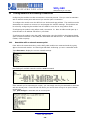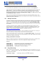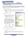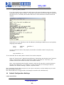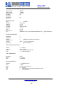
1
WiFly GSX
WiFlyGSX-um.pdf 6/15/2009
WIFLY GSX
RN-131G & RN-134
802.11 b/g wireless LAN Module
User Manual and Command Reference
Version 2.08
Copyright © 2009 Roving Networks, Inc.
All Rights Reserved.
The contents of this document can be changed by Roving networks without prior notice and do not
constitute any binding undertakings from Roving networks. Roving Networks is not responsible under
any circumstances for direct, indirect, unexpected or consequent damage that is caused by this
document.
WiFly GSX
WiFlyGSX-um.pdf 6/15/2009
Contents
1
2
Overview ............................................................................................................................................ 3
Hardware Interface ............................................................................................................................. 4
2.1 Power ......................................................................................................................................... 4
2.2 Reset .......................................................................................................................................... 4
2.3 UART ........................................................................................................................................ 4
2.4 Status Indictors ........................................................................................................................... 4
3 Configuration...................................................................................................................................... 5
3.1 Entering Command Mode ........................................................................................................... 5
4 WiFly Command Reference ................................................................................................................ 6
4.1 Command Syntax ....................................................................................................................... 6
4.2 Command Organization .............................................................................................................. 6
5 SET Commands .................................................................................................................................. 7
5.1 COMM Parameters..................................................................................................................... 7
5.2 DNS Parameters ......................................................................................................................... 7
5.3 FTP Parameters .......................................................................................................................... 8
5.4 IP Parameters ............................................................................................................................. 8
5.5 SYSTEM Parameters.................................................................................................................. 9
5.6 TIME Server Parameters ............................................................................................................ 9
5.7 UART Parameters .................................................................................................................... 10
5.8 WLAN Parameters ................................................................................................................... 10
6 GET Commands ............................................................................................................................... 12
7 STATUS Commands ........................................................................................................................ 13
8 ACTION Commands ........................................................................................................................ 13
9 FILE IO Commands.......................................................................................................................... 14
10 Advanced Features and Settings ........................................................................................................ 16
10.1
System Timers and Auto Connect ......................................................................................... 16
10.2
Wake on Sensor Input ........................................................................................................... 16
10.3
Wake on UART .................................................................................................................... 17
10.4
Uart Receiver, RTS/CTS Hardware Flow Control ................................................................. 17
10.5
Setting PIO directions, Disabling LED drivers ...................................................................... 17
10.6
Alternate IO functions ........................................................................................................... 18
10.7
Setting Debug Print levels ..................................................................................................... 18
11 Joining Networks and Making Connections ...................................................................................... 19
11.1
Associate with a network access point ................................................................................... 19
11.2
Making Connections ............................................................................................................. 20
11.3
Using DNS settings ............................................................................................................... 20
11.4
Utilizing the Backup IP address/connect function.................................................................. 21
12 Firmware Upgrade over FTP ............................................................................................................. 21
13 Adhoc Networking Mode .................................................................................................................. 23
14 Default Configuration Settings .......................................................................................................... 24
14.1
Restoring Default configuration settings: .............................................................................. 26
15 Boot-up Timing Values ..................................................................................................................... 26
16 Know Issues and Errata..................................................................................................................... 27
www.rovingnetworks.com
[email protected]
Phone 408-395-6539
-2-
WiFly GSX
WiFlyGSX-um.pdf 6/15/2009
1
Overview
The “WiFly” radio module is a complete, stand alone, embedded wireless LAN access device.
The device has on board TCP/IP stack and applications. Requiring only 4 pins (POWER, TX, RX,
GND) to design in. Once initial configuration is set, the radio can automatically access the WiFi
network and send/receive serial data over UART.
•
Qualified 2.4GHz IEEE 802.11b/g transceiver
•
High throughput, up to 4Mbps sustained data rate with TCP/IP and WPA2
•
Ultra-low power (4uA sleep, 40mA Rx, 210mA max Tx)
•
Small, compact surface mount module
•
On board ceramic chip antenna and U.FL connector for external antenna
•
8 Mbit flash memory and 128 KB RAM
•
UART and SPI (future) data/control interfaces
•
10 general purpose digital I/O
•
8 analog inputs
•
Real-time clock for wakeup and time stamping/data logging
•
Accepts 3.3V regulated or 2-3V battery with on board boost regulators
•
Supports Adhoc and Infrastructure mode connections
•
On board ECOS-OS, TCP/IP stacks
•
Wi-Fi Alliance certified for WPA2-PSK
•
FCC / CE/ ICS certified and RoHS compliant
Features
•
Host Data Rate Up to 2.7 Mbps for UART
•
Memory 128 KB RAM,2MB ROM, 2 KB battery-backed memory, 8 Mbit Flash.
•
Intelligent, built-in power management with programmable wakeup
•
Can be powered from regulated 3.3-3.7V source or 2.0-3.0V batteries
•
Real time clock for time stamping, auto-sleep and auto-wakeup modes
•
Configuration over UART or wireless interfaces using simple ASCII commands
•
Over the air firmware upgrade (FTP), and data file upload.
•
Secure WiFi authentication WEP-128, WPA-PSK (TKIP), WPA2-PSK (AES).
•
Built in networking applications DHCP client, UDP, DNS client , ARP, ICMP ping, FTP, HTTP
•
802.11 power save and roaming functions
www.rovingnetworks.com
[email protected]
Phone 408-395-6539
-3-
WiFly GSX
WiFlyGSX-um.pdf 6/15/2009
2
Hardware Interface
See the RN-131 data sheet on the Roving Networks website for technical specifications and
layout information. (Document rn-131-ds.pdf)
2.1
Power
There are two options for powering the RN-131G module directly.
1. DC SUPPLY: Apply 3.3 VDC power to VBATT (pin 20), AND V3.3IN (pin 21)
Tie 3.3VREG-IN (pin 18) to GROUND. 3.3V-REG-OUT (Pin 17) leave floating.
2.
2.2
BATTERY: Apply battery = 2.0 to 3.3VDc to VBATT (pin 20). V3.3IN pin 21 = floating.
Tie pin 17 to pin 18. (this enables the on board battery boost 3.3V switcher).
Reset
Reset is active LOW and is optional/does not need to be connected. The reset pin is 3.3V
tolerant and has an internal pullup of 100K to the VBATT. There is also a built in voltage
brownout monitor.
2.3
UART
•
•
•
Connect a common ground when using the external TX, RX inputs.
For a 3 wire DB-9 interface (tx, rx, gnd only) Factory default is hardware flow control
disabled, CTS and RTS are not required.
When using a 5.0Vdc Input, PIO’s and UART input pins require a resistor divider. A
suggestion is 10K in series with 20k to ground. PIO’s are 0-3.3Vdc not 5 volt tolerant.
Warning: Do NOT exceed the voltage ratings on the 3.3V pins, damage to the module will
result.
Important Notes:
#1: The Sensor inputs SENS0-7 are extremely sensitive to over voltage. Under no
conditions should these pins be driven above 1.2VDC. Placing any voltage above
this will permanently damage the radio module and render it useless.
#2: Placing 5VDC or any voltage above 3.3Vdc into the VDD pins of the module will
permanently damage the radio module.
#3: Placing 3.3Vdc into the PIO’s while they are set as outputs will permanently
damage the radio modules. The failure mode is a short across GND and VCC.
2.4
Status Indictors
PIO 4, 5 and 6 are active high and can be connected to external LEDs to provide status.
Condition
PIO6=Red LED
ON solid
Not Associated
Fast blink
PIO5=Yellow LED
Connected over TCP
Rx/Tx data transfer
Slow blink
Associated, No Internet
OFF
Associated, Internet OK
PIO4=Green LED
No IP address
IP address OK
www.rovingnetworks.com
[email protected]
Phone 408-395-6539
-4-
WiFly GSX
WiFlyGSX-um.pdf 6/15/2009
3
Configuration
3.1
Entering Command Mode
Upon power up, the device will be in data mode. To enter command mode, exactly the three
characters $$$ must be sent. The device will respond with CMD.
While in command mode, the device will accept ASCII bytes as commands.
To exit command mode, send exit<cr>. The device will respond with “EXIT”.
Parameters, such as the SSID, channel, IP address, Serial Port settings, and all other settings can
be viewed and configured in command mode.
ASCII characters can be sent through a terminal emulator connected to the UART or via Telnet.
When using the UART communications settings should match the settings used when RN-131g
connects, for example: the default is 9600 baudrate, 8 bits, No Parity, 1 stop bit, and hardware
flow control disabled.
Run your favorite terminal emulator, Roving Networks provides a free one, Teraterm, at
http://www.rovingnetworks.com/support/teraterm.zip.
Type $$$ on in the terminal emulator. You should see “CMD” returned to you. This will verify
that your cable and comm. settings are correct. Most valid commands will return an “AOK”,
response, and invalid ones will return an “ERR” description.
To exit command mode,
type
“exit“<cr>.
NOTE: You can enter command mode locally over the serial port at any time when not
connected, and also when connected if the appropriate settings are enabled.
Over the air, Remote configuration
Once the module has associated and if TCP SERVER is enabled (the default) the device will be
listening for connections on port 2000.
Using Windows XP, Linux, Mac, or any other TCP client you can access remote configuration.
Example: (windows command line)
Response “*HELLO*”
telnet 10.10.10.149 2000
You can now enter command mode and configure the module.
www.rovingnetworks.com
[email protected]
Phone 408-395-6539
-5-
WiFly GSX
WiFlyGSX-um.pdf 6/15/2009
4
WiFly Command Reference
4.1
Command Syntax
Commands begin with a keyword, and have optional additional parameters, generally space
delimited. Commands and options are case sensitive. Hex input data can be upper or lower
case. String text data, such as SSID is also case sensitive.
The first command is fully decoded and must be complete. Other command parameters can be
shorted by using only the first character.
For example,
set uart baudrate 115200 is valid,
set uart b 115200
set u b 115200
is also valid,
is also valid, however,
s uart baudrate 115200
is NOT valid.
Numbers can be entered as either decimal, (like 115200 above) or HEX. To enter HEX, use
0x<value>. For example, the HEX value FF would be entered as 0xFF.
4.2
Command Organization
Commands fall into 5 general categories:
•
SET COMMANDS -Take effect immediately, permanently (save command issued).
•
GET COMMANDS -Retrieve the permanently stored information for display to user.
•
STATUS COMMANDS -See what is going on with the interface, IP status, etc.
•
ACTION COMMANDS- Perform action such as scan, connect, disconnect, etc.
•
FILE IO COMMANDS - Upgrade, load and save configuration, delete files, etc.
NOTE: You must save any changes made or the module will load the previous settings upon
reboot or power up.
When the system boots, all configuration data is loaded into RAM variables from the file called
“config”. The set commands actually only modify the RAM copy of variables in the system.
This allows temporary change of parameters “on the fly” to test features, minimizes power usage
and saves on flash re-write cycles.
Once all configuration is complete, the user must save the settings using the save command to
store the configuration data, otherwise it will not take effect upon reboot or reset. Multiple
configurations can be stored by using the save <filename> command, and these
configurations can be loaded using the load <filename> command. These files can be uploaded
to remote FTP site, such that once a desired configuration is created, it can quickly be copied into
additional devices (cloning).
www.rovingnetworks.com
[email protected]
Phone 408-395-6539
-6-
WiFly GSX
WiFlyGSX-um.pdf 6/15/2009
5
SET Commands
These commands begin with “set”. There are 6 major categories.
•
•
•
•
•
•
•
•
5.1
COMM
DNS
FTP
IP
SYS
TIME
UART
WLAN
-
communication and data transfer, timers, matching characters
DNS host and domain
FTP host address and login information
IP settings
system settings such as sleep and wake timers
timer server settings
serial port settings such as baudrate and parity
wireless interface settings, such as ssid, chan, and security options
COMM Parameters
set comm close <string>
sets the ASCI string that is sent to the local UART when the TCP
port is closed. If no string is desired, use 0 as the <string>
parameter. Max string length is 32 characters. Default is *CLOS*
set comm open <string>
sets the string that is sent to the local UART when the TCP port is
opened. If no string is desired, use 0 as the <string> parameter.
Max string length is 32 characters. Default is *OPEN*
set comm remote <string>
sets the string that is sent to the remote TCP client when the TCP
port is opened. If no string is desired, use 0 as the <string>
parameter. Max string length is 32 characters. Default is *HELLO*
set comm idle <secs>
sets the Idle Timer Value. This is the number of seconds with no
transmit or receive data before the connection is closed
automatically. Default is 0, never disconnect on idle.
set comm match <value>
sets matching character initiate forwarding data across the TCP/IP
connection. The value is entered as the decimal value of the of
the ASCII character. Default is 0, disabled. For more information
see section 10.4.
set comm size <value>
sets the Flush Size value. This is the number of bytes to receive
on the UART before forwarding, 0 or 1 forwards immediately.
Default is 16 bytes. Maximum value = 1420 bytes.
set comm time <num>
sets the Flush Timer. This is the number of 1 millisecond intervals
after a UART byte is received before the data is sent over Wifi, 1 is
the minimum value. Default is 10 (10 milliseconds). Setting this
value to 0 will disable the feature.
5.2
DNS Parameters
set dns address <addr>
sets the IP address of the DNS sever. This is auto-set when using
DHCP, so only used used in STATIC IP mode.
set dns name <string>
sets the name of the host for TCP/IP connections.
set dns backup <string>
sets the name of the backup host for TCP/IP connections.
www.rovingnetworks.com
[email protected]
Phone 408-395-6539
-7-
WiFly GSX
WiFlyGSX-um.pdf 6/15/2009
5.3
FTP Parameters
set ftp filename <file>
sets the name of the file transferred when issuing the “ftp u” or
“ftp g” commands.
set ftp addr <addr>
sets the ftp server IP address.
set ftp user <name>
sets the ftp user name for accessing the FTP server.
set ftp pass <pass>
sets the ftp password for accessing the FTP server.
5.4
IP Parameters
set ip address <addr>
sets the IP address of the WiFly GSX module. If DHCP is turned
on, the IP address is assigned and overwritten during association
with the access point. IP addresses are “.” delimited. Note this is
different from the RN-111b module which is space delimited!
Example: “set ip a 10.20.20.1”
set ip dchp <0,1>
enable or disable DHCP client. If DHCP is turned on, the IP,
gateway and net mask are assigned and overwritten during
association with the access point.
set ip gateway <addr>
sets the gateway IP address, If DHCP is turned on, the gateway IP
address is assign and overwritten during association with the
access point.
set ip host <addr>
sets the remote host IP address. This command is used for
making connections from the WiFly module to a TCP/IP server at
the IP address <addr>.
set ip backup <addr>
sets a secondary host IP address.
set ip localport <num>
sets the local port number.
set ip netmask <value>
sets the network mask. If DHCP is turned on, the net mask is
assign and overwritten during association with the access point.
set ip protocol <value>
sets the IP protocol. Value is a bit mapped setting. To connect to
the WiFly GSX module over TCP/IP such as Telnet the device must
have the use the TCP Server protocol / bit 2 set. To accept both
TCP and UDP use value = 3 (bit 1 and bit 2 set)
Bit Position
1
2
3
4
5
set ip remote <value>
Protocol
UDP
TCP Server & Client (Default)
Secure (only receive packets with IP address
matches the store host IP)
TCP Client only
HTTP (future use)
sets the remote host port number.
www.rovingnetworks.com
[email protected]
Phone 408-395-6539
-8-
WiFly GSX
WiFlyGSX-um.pdf 6/15/2009
5.5
SYSTEM Parameters
set sys autoconn <secs>
TCP mode: sets the auto connect timer. The auto connect timer
will attempt to connect to the stored remote host IP every <secs>
seconds. If set to once the module will only make one attempt to
auto connect. This command can be used to have the module
periodically connect to the host. 0 is the default and disables auto
connect.
set sys autosleep <num>
UDP mode: sets the auto-sleep timer. 0 disables.
set sys iofunc
sets the IO port alternate functions. Bit-mapped value. For more
details see section 10.6
set sys mask
<value>
<mask>
set sys printlvl <value>
sets the IO port direction mask. Bit-mapped value. For more
information see section 10.5
sets numerous print functions. 0 = quiet 1 = connect information
Default is 1.
set sys output <value> <mask> sets output PIO pins to HIGH or LOW. Bit-mapped value.
Optional mask only sets a subset of pins.
set sys sleep
<secs>
sets the sleep timer. 0 disables.
NOTE: If not using Sensor pins to wake the module, be sure to set
the wake timer before issuing the sleep timer or the module will
not wake up.
See section 0 for more details on using system timers
set sys trigger <value>
sets the sensor input(s) to wake on (1-4). Bit-mapped value.
disables.
set sys wake
sets the auto wake timer. 0 disables. See section 0 for more
details on using system timers
5.6
<secs>
0
TIME Server Parameters
set time address <addr>
sets the time server address. (sNTP servers)
set time port <num>
sets the time server port number. Defaults to 123 which is almost
always the sNTP server port.
set time enable <value>
Enable or disable fetching time from the specified sNTP time
server. Default is 0 = don’t. A value or 1 gets time only once on
power up. Any value > 1 gets time continuously every <value>
minutes.
www.rovingnetworks.com
[email protected]
Phone 408-395-6539
-9-
WiFly GSX
WiFlyGSX-um.pdf 6/15/2009
5.7
UART Parameters
set uart parity <n,e,o>
sets the UART parity.
Example : “set u p e” sets even parity
set uart baud <rate>
set the UART baud rate. Valid settings are {1200, 2400, 4800,
9600, 19200, 38400, 57600, 115200, 230400, 460800, 921600}.
Example : “set u b 9600” sets the baud rate to 9600 baud.
set uart raw <rate>
sets a RAW UART value. Used to set non-standard rates.
Example : “set u r 760” sets the baud rate to 7200 baud.
set uart flow <0,1>
sets the flow control mode. 0=off, 1= hardware RTS/CTS.
set uart tx
Disables or enables the TX pin= PIO0 of the UART.
set PIO0 to an INPUT with weak pulldown.
5.8
<0, 1>
Disable will
WLAN Parameters
set wlan auth <value>
Note: During association the WiFly module interrogates the access
point and automatically selects the authentication mode.
Sets the authentication mode. Not needed unless using auto join
mode 2. i.e. set wlan join 2
Value
0
1
2
3
4
5
6
set wlan channel <value>
Authentication Mode
Open (Default)
WEP-128
WPA1
Mixed WPA1 & WPA2-PSK
WPA2-PSK
Not Used
Adhoc, Join any Adhoc network
sets the wlan channel, 1-13 is the valid range for a fixed channel.
If 0 is set, then scan is performed, using the ssid, for all the
channels set in the channel mask.
set wlan ext_antenna <0, 1> determines which antenna is active, use 0 for chip antenna, 1 for
UF.L connector. Only one antenna is active at a time and the
module must be power cycled after switching the antenna for the
change to take effect.
www.rovingnetworks.com
[email protected]
Phone 408-395-6539
- 10 -
WiFly GSX
WiFlyGSX-um.pdf 6/15/2009
set wlan join <value>
sets the policy for automatically joining/associating with network
access points. This policy is used when the module powers up,
including wake up from the sleep timer.
Value
0
1
2
3
4
Policy
Manual, do not try to join automatically
Try to join the access point that matches the
stored SSID, passkey and channel. Channel can
be set to 0 for scanning. (Default)
Join ANY access point that is running security
matches the stored authentication mode. This
ignores the stored SSID and searches for the
access point with the strongest signal. The
channels searched can be limited by setting the
channel mask.
Reserved – Not used
Create and adhoc network. Create a psudo access
point using stored SSID, IP address and netmask.
DHCP should be turned off with this policy.
This policy is used instead of the hardware jumper
set wlan hide <0, 1>
Hides the WEP key and WPA passphrase. When set, displaying
the wlan settings shows ****** for these fields. To unhide the
passphrase or passkey, re-enter the key or passphrase using the
set wlan key or set wlan passphrase command. Default = 0, do
not hide.
wlan key <num> <value>
sets the WEP key. key must be EXACTLY 13 bytes (26 ASCII
chars). Data is expected in HEX format, “0x” should NOT be used
here.
Example : “set w k 112233445566778899AABBCCDD”
Hex digits > 9 can be either upper or lower case.
set wlan mask <value>
sets the wlan channel mask used for scanning channels with the
auto-join policy 2, Value is a bit-map where bit 0 = channel 1.
Input for this command can be entered in decimal or hex if
prefixed with 0x. Default value is 0x1FFF (all channels)
set wlan num <value>
sets the default WEP key to use. 1-4 is the valid range.
Example : “set w n 2” sets the default key to 2.
set wlan phrase <string>
sets the passphrase for WPA and WPA2 security modes. 1-64
chars. The passphrase can be alpha and numeric, and is used
along with the ssid to generate a unique 32 byte Pre-shared key
(PSK), which is then hashed into a 256 bit number.
However, if exactly 64 chars are entered, it is assumed that this
entry is already an ASCII HEX representation of the 32 byte PSK
and no such processing is done.
www.rovingnetworks.com
[email protected]
Phone 408-395-6539
- 11 -
WiFly GSX
WiFlyGSX-um.pdf 6/15/2009
Example : “set w p password” sets the phrase.
set wlan ssid <string>
sets the wlan ssid to associate with. 1-32 chars.
NOTE: If the passphrase or ssid contain the SPACE ( ‘ ‘)
characters, these can be entered using substitution via the
“$” character.
For example, if the ssid of the AP is
You would enter
“yellow brick road”
Using the ‘get w” command will properly display the value:
SSID=yellow brick road.
set wlan rate <value>
sets the wireless data rate. Lowering the rate increases the
effective range of the WiFly-GSX module. The value entered is
mapped according to the following table
Value
0
1
2
3
4-7
8
9
10
11
12
13
14
15
set wlan window <value>
6
Wireless Data Rate
1 Mbit/sec
2 Mbit/sec
5.5 Mbit/sec
11 Mbit/sec
Invalid
6 Mbit/sec
9 Mbit/sec
12 Mbit/sec (Default)
18 Mbit/sec
24 Mbit/sec
36 Mbit/sec
48 Mbit/sec
54 Mbit/sec
sets the IP max. buffer size. Default is 1460 bytes.
GET Commands
These commands begin with “get”. They display the current values.
get all
display all configuration settings. Useful for debug
get com
display comm. settings.
get dns
display DNS settings.
get ftp
display FTP settings.
get ip
display IP address and port number settings.
get mac
display the device MAC address.
www.rovingnetworks.com
[email protected]
Phone 408-395-6539
- 12 -
WiFly GSX
WiFlyGSX-um.pdf 6/15/2009
get port
return current value of the PIO pins in hex format.
get sys
display system settings, sleep, wake timers, etc.
get time
display the time server UDP address and port number.
get wlan
display the ssid, chan, and other wlan settings.
get uart
display the UART settings.
ver
return the software release version
7
STATUS Commands
These commands begin with “show”, and they return the current values of variables in the system.
In some cases, for example IP addresses, the current values are received from the network, and
may not match the stored values.
show net
Displays current network status, association, authentication, etc.
show rssi
Displays current last received signal strength.
show stats
Displays current statistics, packet rx/tx counters, etc.
show time
Displays number of seconds since last powerup or reboot
show i
Displays IO pin levels status in this HEX format: 8ABC
Example: show I returns 8103 indicates pins 0, 1 and 9 high
level.
show c
Displays connection status in this HEX format: 8XYZ
Bit loc
function
value
8
13-16
fixed
8
9-12
channel
1-13
7
DNS found
1=resolved
6
DNS server
1=
contacted
5
Authen
1= OK
4
Assoc
1=OK
0-3
TCP status
0= Idle,
1=Connected
3= NOIP
4= Connecting
ACTION Commands
$$$
enter command mode Characters are PASSED until this exact
sequence is seen. If any bytes are seen before these chars, or
after these chars, in a 1 second window, command mode will not
be entered and these bytes will be passed on to other side.
close
disconnect a TCP connection.
exit
exit command mode. Exit command mode. “EXIT” will be
displayed.
www.rovingnetworks.com
[email protected]
Phone 408-395-6539
- 13 -
WiFly GSX
WiFlyGSX-um.pdf 6/15/2009
factory RESET
Loads factory defaults into the RAM configuration. Note that the
RESET must be capitalized. After this command the new
settings must be save to the config file using the save command
and the module rebooted for them to take effect.
join <ssid>
joins the network <ssid>. If network is security enabled you
must set the pass phrase with the set wlan phrase command
prior to issuing the join command
join # <num>
join a network from the scan list. <num> is the entry number in
the scan list that is returned from the scan command. If network
is security enabled you must set the pass phrase with the set
wlan phrase command prior to issuing the join command
open <addr> <port>
opens a TCP connection to the given IP port and address. If no
arguments are provided, the device will attempt to connect to the
stored remote host IP address and remote port number.
<addr> can also be a DNS hostname and will be resolved if
entered.
Ping <g | h | i | addr> <num> ping remote host. Default sends 1 packet. Optional <num> sends
<num> pings at 10 per second.
Ping 10.20.20.12 10 – pings IP address 10 times
ping g
pings the gateway, the gateway IP address is loaded if
DHCP is turned on, otherwise it should be set with the
set ip gateway <addr> command
ping h
pings the stored host IP address, the host IP address
can be set with the set ip host <addr> command
ping i
pings a known Internet server at www.neelum.com by
first resolving the URL (proves that DNS is working and
proves the device has internet connectivity).
ping 0
terminates a ping command
reboot
forces a reboot of the device (similar to power cycle)
scan
Performs an active probe scan of access points on all 13 channels,
and prints out MAC address, receive signal strength, and SSID
name.
NOTE: Unlike the RN-111B, this command can scan for access
point and remain associated .
time
9
Sends a UDP time server request packet out.
FILE IO Commands
www.rovingnetworks.com
[email protected]
Phone 408-395-6539
- 14 -
WiFly GSX
WiFlyGSX-um.pdf 6/15/2009
del <name> <num>
Deletes a file. Optional <num> will override the name and use
the sector number shown in the “ls” command.
load <name>
Reads in a new config file.
ls
Displays the files in the system
save
Saves the configuration to “config” (the default file).
save <name>
Saves the configuration data to a new file name
boot image <num>
Makes file <num> the new boot image.
ftp get <name>
Retrieves a file from the remote FTP server.
specified, the stored ftp filename is used.
ftp update <name>
Deletes the backup image, retrieves new image and updates the
boot image.
www.rovingnetworks.com
[email protected]
Phone 408-395-6539
- 15 -
If <name> not
WiFly GSX
WiFlyGSX-um.pdf 6/15/2009
10
Advanced Features and Settings
10.1
System Timers and Auto Connect
There are 2 timers that can be used to put the module to sleep, and perform a wake up.
If the sleep timer is enabled, the module will automatically go into low power mode after the
timer counts down to 0. The countdown is disabled if the module has an IP connection, or the
module is in COMMAND mode. The timer is reset when characters are received on the UART.
The sleep timer is set with : set sys sleep <time>
time=decimal in seconds.
The wake timer is set with:
time=decimal in seconds.
set sys wake <time>
UDP sleep, and Connection timers
There is another timer than can be used to put the device to sleep.
In UDP protocol mode, the auto-conn timer is re-defined as an auto-sleep timer.
Upon the start of transmission of the first UDP data packet this timer will count down.
set sys autosleep <value> UDP mode: sets the auto-sleep timer. 0 disables
the timer is decremented every xx milliseconds, based on the value of the comm. flushtimer.
Using a minimum value of 2 (when the default flushtime=10 ms ) is recommended to ensure
that the UDP packet gets transmitted. For larger packets the value should be increased.
In TCP-Client mode, the auto-conn timer is used as a connect out timer. If set, the device will
automatically attempt a connection when the timer expires.
set sys autoconn <secs>
In TCP-Client AND TCP-Server mode, there is also a disconnect timer.
set comm idle <secs> sets the idle disconnect timer. This causes a disconnect if no transmit
or receive data is seen.
10.2
Wake on Sensor Input
There are 4 inputs available to wake the module from sleep,
SENS0-3..
To enable 1 of these inputs, use: set sys trigger <value>. 0 disables. This is a bitmapped setting. To wake on sensor pin 2, you would use set sys trig 4, for example.
Unlike the RN-111b, The SENSE inputs do NOT have a resistor divider to allows pins to
tolerate 3V logic.
So a minimum of 24K in series with 10K to ground as a divider network
from the UART RX or CTS pin should be used.
WARNING: Under no conditions should the voltage on any SENS0-7 input exceed
1.2VDC. Permanent damage to the module will result.
The SENS0-3 inputs have a small current source that is activated in sleep mode. This source
is approximately 100nA, and will cause the input to float up to about 1.2VDC.
IF SENSE1 for
example, is enabled, pulling the SENS1 pin to GROUND will wake the device. An open drain
FET is a good device to tie to the pin. The threshold is about 500mV. Additional pullup to
www.rovingnetworks.com
[email protected]
Phone 408-395-6539
- 16 -
WiFly GSX
WiFlyGSX-um.pdf 6/15/2009
1.2VDC may need be used if the circuit has an impedance (due to leakage current) of less
than 5Mohms ( 500mv / 100nA ). SENS1-4 pins that are not used should be left
unconnected.
10.3
Wake on UART
When the module is in Sleep mode, the UART itself is disabled. However, wake on UART can
be accomplished by connecting the SENS1 pin to the RX data pin. (using appropriate divider
resistors mentioned above)
The SuRFboard for example, has built in resistor dividers to
allow wake from RXD or CTS pins.
To enable wake on RXD , use set sys trig 1.
It should be noted that the first (or possibly multiple) byte sent into the module will likely be
lost, so the designer should take care to send a preamble byte to wake up the module before
sending valid data bytes.
A better way to do this is to use the CTS input to wake the
module, and wait until it is ready to accept data. To enable this, use set sys trig 2.
10.4
Uart Receiver, RTS/CTS Hardware Flow Control
The UART receive buffer is approx. 1024 bytes, and at lower baudrates (9600, 19200) the
system can process data into the device without need for flow control.
If constant streaming of data into RX on the device is required, care should be taken to set the
comm parameters to optimize the performance. If data has a termination char, this can be
used. Also, if data has a particular frame size, this can be used.
set comm match <value>
sets the value of the packet terminator.
set comm size <value> sets the number of bytes to receive before forwarding
0-1 forwards immediately. maximum value = 1460 bytes.
The comm size is automatically set whenever the baudrate is set, but can be modified.
Even at higher baudrates (115K and higher ) it is possible to operate without flow control if
packets are uniform and a protocol is used to ensure that data is delivered on the remote side
before the next packet is sent.
However, given the uncertainty of packet delays in a TCP/IP network and the affects of
interference and retries inherent in wireless networks, flow control is usually required to
guarantee no data is lost.
By default flow control is disabled. To enable hardware flow contol, use set uart flow 1.
10.5
Setting PIO directions, Disabling LED drivers
The table below shows the usage of the PIO pins and their default values:
Use the command: set sys mask <hex val> to enable or disable certain pins as outputs.
For example, set sys mask 0 will default all pins to INPUT.
www.rovingnetworks.com
[email protected]
Phone 408-395-6539
- 17 -
WiFly GSX
WiFlyGSX-um.pdf 6/15/2009
10.6
PIO
State
9
input
DESCRIPTION
8
output
Spare GPIO
7
output
Spare GPIO, BLUE LED on WiFly Serial Adapter
6
output
RED LED- (Associated, internet OK/ TCP conn )
5
output
YELLOW LED – (wifi RX or RSSI )
4
output
GREEN LED - (system status /ASSOC-AUTH)
13
output
12
input
1
input
UART RTS – goes HIGH on POWERUP, LOW once system is READY.
If HW Flow control enabled, toggles HIGH to indicate RX buffer full.
UART CTS – throttles transmitter if HW flow control enabled.
LOW enables transmitter, HIGH will disable.
UART RX
0
output
Used for factory reset
UART TX
Alternate IO functions
There are a number of alternate IO functions that can be enabled. These functions override
the default IO function given in section 4.4, and described in the LED table of section 2.3.
If no bits are set for a particular PIO pin, then the is driven by the firmware as LED status.
set sys iofunc <value> sets numerous alternate functions. Bit-mapped value.
Bit
0
1
2
3
4
5
6
10.7
IO
DIRECTION
PIO4 PIO5 PIO6 not used
PIO4 - Output.
PIO5 - Input.
PIO6 - Output.
Function
Disable LED function so IO can be used as GPIO
Disable LED function so IO can be used as GPIO
Disable LED function so IO can be used as GPIO
HIGH once associated/authenticated and have IP address.
Set HIGH to trigger TCP connection, LOW to disconnect.
HIGH when connected over TCP, LOW when disconnected.
Setting Debug Print levels
There are a number of print functions that can be enabled to assist in debugging the operation
and status of the module. The following command is used to control these printouts.
set sys printlvl <value> sets additional print functions. Bit-mapped value.
Bit
1
Function
Print startup messages showing progress of association, dhcp, etc.
Once the configuration has been checked, this can then be turned off so that these messages
do not interfere with the datastream.
www.rovingnetworks.com
[email protected]
Phone 408-395-6539
- 18 -
WiFly GSX
WiFlyGSX-um.pdf 6/15/2009
11
Joining Networks and Making Connections
Configuring the module to make connections is a two set process. First you need to associate
with a network access point and second you need to open a connection.
To configure the module over the WiFi link is a chicken and egg problem. The module must be
associated to a network to connect to it and program the network settings. This problem can
be solved by configuring the module from the UART or over the air using adhoc mode.
If configuring the module using adhoc mode, see section 13. Once in adhoc mode open up a
telnet window on IP address 169.254.1.1 port 2000
If configuring the module using the UART mode either using the RS232 or development board,
open a terminal emulator on the COM port associated with that deveice. The default baud rate
is 9600, 8 bits no parity.
11.1
Associate with a network access point
From within the terminal window, put the WiFly GSX module into command mode by typing
$$$ in the terminal window. You should get CMD back confirming you are in command mode.
Type show net to display the current network settings.
Now finding all available networks with the scan command
If the network you’re connecting to is open, you can simply use the join command to associate
with the access point. From the scan list above you can see that roving1 is an open network
access point.
Type join roving1 to associate with an access point.
www.rovingnetworks.com
[email protected]
Phone 408-395-6539
- 19 -
WiFly GSX
WiFlyGSX-um.pdf 6/15/2009
You could also have specified the roving1 access point by using the command join # 1
If the access point is security enabled you will need to set the pass phrase prior to issuing the
join command. The RN-131G module will attempt to inquire and determine the security
protocol of the access point so you do not have to set the authentication mode. To set the
pass phrase for WPA use the command set wlan phrase <string>. For WEP set the key using
the set wlan key <num> command.
Once you have successfully associated to the network the access point SSID is stored. This
along with the pass phrase can be saved to the config file so the module can associate with the
network each time it is booted up.
11.2
Making Connections
To make a connection into the module simply open a IP socket and connect to the IP address of
the module. Telnet is a simple way to test this connection. From in Telnet type open <addr>
<port>. In the example above the telnet command you look like open 10.20.20.62 2000.
Once open you can type characters into the UART window and see them on the Telnet window
or visa versa.
To make a connection from the module you will need IP address and port number of your
server application. A simple program to test this functionality is a COM port redirector. This
software opens an IP port and transfers all data it receives to a specified COM port on your
machine. A free com port redirector program is available from Pira at
http://www.pira.cz/eng/piracom.htm
After installing and starting this program, note the IP address of the machine it is running on.
This can be found by running ipconfig in the Microsoft command window.
With the WiFly-GSX module in command mode, type open <addr> <port>. The server will
report the connection is open and you can type characters into the UART window and see them
on the server window or visa versa.
Setting up Automatic Connections
Often, it is desired to powerup (or wakeup) and automatically connect out to a remote server,
send data, and then disconnect. This can be configured to happen automatically.
Example:
set
set
set
set
11.3
sys auto 3
com idle 5
sys sleep 10
sys wake 60
( automatically connect out 3 seconds after READY )
( disconnect 5 seconds after no data activity )
( sleep 10 seconds after connection is closed )
(wakeup after 1 minute of sleeping )
Using DNS settings
WiFly contains a built in DNS client. If the IP address of the host is not specified (i.e it is set
to 0.0.0.0) , DNS will be used. WiFLY will automatically attempt to resolve the host address
stored with the command:
set dns name <string>
sets the name of the host for TCP/IP connections.
www.rovingnetworks.com
[email protected]
Phone 408-395-6539
- 20 -
WiFly GSX
WiFlyGSX-um.pdf 6/15/2009
Once the address is resolved an automatic connection will be made.
11.4
Utilizing the Backup IP address/connect function
WiFly contains a feature for auto-retry and redundancy. If the first IP host address connection
fails, the backup IP will be used (if set) . If this fails (or is not set) then the first DNS name
will be used. If this fails (or is not set) then the Backup DNS name will be used.
To set the backup IP address,
use:
set ip backup <address>
To set the backup DNS name, use:
set dns backup <string>
12
Firmware Upgrade over FTP
WiFly module has a file system for storing firmware, web pages and config files. Use the ls
command to view files. File size is displayed in sectors and the active boot image is identifyied.
FL#
11
29
SIZ
18
1
FLAGS
3
10
WiFly_GSX-2.05
config
190 Free, Boot=11, Backup=0
Multiple firmware images and config files can be stored in the module filesystem.
FTP Upload and Upgrade
WiFly contains a built in FTP client for getting files and updating the firmware.
passive mode FTP, which allows operation thru firewalls and the Internet.
The client uses
To upload the latest released firmware from Roving Networks the following setting are required:
FTP
FTP
FTP
FTP
username = roving
password = Pass123
filename = wifly-GSX.img
directory = ./public (this parameter can not be modified)
To use FTP to upgrade the firmware, enter the following command:
ftp upload <string>
(string is an optional filename, use to bypass the stored FTP filename)
The ftp upload command will retrieve the file and switch the boot image to the new file. The
previous firmware will become the backup image. Here is an example of what you should see
after a successful update:
FL#
11
29
30
SIZ
18
1
18
FLAGS
3
10
3
WiFly_GSX-2.05
config
WiFly_GSX-2.06
www.rovingnetworks.com
[email protected]
Phone 408-395-6539
- 21 -
WiFly GSX
WiFlyGSX-um.pdf 6/15/2009
208 Free, Boot=30, Backup=11
Note the module must be rebooted or power cycled to use the new firmware. To boot a different
firmware use the following command:
Boot image <num>
sets the current boot image <num>
To upload your own firmware or config file to the module, change the stored FTP settings: See
section 5.3 for more details on these commands and get your file by entering the following
command:
ftp get <string>
Retrieves remote file with name <string>
www.rovingnetworks.com
[email protected]
Phone 408-395-6539
- 22 -
WiFly GSX
WiFlyGSX-um.pdf 6/15/2009
13
Adhoc Networking Mode
The WiFly GSX module can be configured to setup an adhoc network. This mode is useful for point to
point communications. The WiFly device is in Adhoc mode the device looks like access point for other
WiFi devices to join. Note: currently the WiFly only supports OPEN mode for creating adhoc
networks. Adhoc mode can be set via hardware or software commands.
To enable adhoc mode via hardware:
Set PIO9 high (3.3V) at power up. On the RN-134 PIO9 is on J1 of the jumper block. When
the module powers up in adhoc mode the WiFly module creates an adhoc network with the
following
SSID:
WiFly-GSX-XX where XX is the final two bytes of the devices MAC
address
IP address: 169.254.1.1
To enable adhoc mode from software:
From command mode, the module is configured
for adhoc mode using the join command. You
will also need to set the ssid and channel.
set wlan
join
4
set wlan
ssid
my_adhoc_network
set wlan
chan 1
Turn off DHCP and set the IP address and
netmask so other devices know where to
connect to the adhoc WiFly GSX. Since auto IP
fixes the first two bytes of the IP address you
want to use the netmask of 255.255.0.0 so that
other device connecting to the module can be
reached. Alternatively you can set the netmask
to a smaller subnet if the other device’s IP
addresses are begin statically to the same
subnet as the adhoc device
set ip
set ip
set ip
address
netmask
dhcp
169.254.1.1
255.255.0.0
0
Be sure to save your configuration, then upon
reboot the module will be in adhoc mode.
To associate with an adhoc network from another WiFly device:
set wlan ssid my_adhoc_network
reboot
or alternatively you can use the join command to associate with the adhoc network.
Remember to disassociated using the leave command if you are previously associated to
another network.
www.rovingnetworks.com
[email protected]
Phone 408-395-6539
- 23 -
WiFly GSX
WiFlyGSX-um.pdf 6/15/2009
join my_adhoc_network
If you leave DHCP service enabled the WiFly device will get an IP address using auto IP when
associating with the adhoc network. By definition auto IP fixes the first two bytes of subnet to
169.254.xxx.xxx. The WiFly device takes about two to three seconds to resolve the auto IP
address.
Alternatively you can statically set the IP address by disabling the DHCP service and explicitly
assigning the IP address.
set ip
set ip
address
dhcp
169.254.1.2
0
You can confirm the device has properly connected to the adhoc network using the ping
command.
ping 169.254.1.1 10
To use associate with the WiFly adhoc network from another computer
Open the “Control Panel / Networking and Sharing / Networking and Sharing Center” dialog in
Vista or “Control Panel / Network Connections” dialog in Windows XP. From here, view
available networks and select the name of the adhoc network.
Note: Once associated with the adhoc network, Vista auto IP may take a couple minutes to
allocate an IP address for your computer. To work around this you can assign a static IP
address in the network settings / TCP/IP / Properties menu.
Once associated with the adhoc network you can open a connection or telnet window as you would
with an enterprise connection.
Note: The module does not support adhoc and enterprise network modes simultaneously.
14
Default Configuration Settings
COMM PARAMETERS
www.rovingnetworks.com
[email protected]
Phone 408-395-6539
- 24 -
WiFly GSX
WiFlyGSX-um.pdf 6/15/2009
Close string
Open string
Remote string
FlushSize
MatchByte
FlushTimer
IdleTimer
*OPEN*
*CLOS*
*HELLO*
16
0
10
0
IP PARAMETERS
dhcp
protocol
address
localport
netmask
gateway
host
remoteport
ftp
1
(enabled)
TCP-Server
0.0.0.0
2000
255.255.255.0
0.0.0.0
0.0.0.0
2000
208.109.78.34 ( roving default update server )
SYSTEM PARAMETERS
sleeptimer
waketimer
trigger
auto connect
iomask
print level
0
0
1
0
0xFC
1
(SENS1 pin wakes up the device)
( 3,4,5,6,7,8 outputs ).
(prints enabled)
TIME SERVER PARAMETERS
enable
address
port
zone
0= disabled
129.6.15.28
123 ( SNTP TIME protocol )
7 ( pacific USA time )
UART PARAMETERS
Baudrate
parity
flow
9600
n (none)
0=disabled
WLAN PARAMETERS
channel
ssid
mask
rate
join
ext
0 (automatic scan )
roving1
0x1FFF ( all channels )
12 (24Mbit)
1 (automatically scan and join based on ssid )
0 (use CHIP ANT )
www.rovingnetworks.com
[email protected]
Phone 408-395-6539
- 25 -
(port fixed at 21)
WiFly GSX
WiFlyGSX-um.pdf 6/15/2009
14.1
Restoring Default configuration settings:
From software use the factory RESET command.
In hardware PIO9 is used to restore the configuration settings to the factory defaults. If PIO9 is set
high (3.3V) at power up time and then toggled five (5) times while the module remains powered on
all the configuration settings will be set back to their factory values.
Note: Factory defaults should be saved to the config file using the save command and the module
rebooted for the new settings to take effect.
15
Boot-up Timing Values
Function
Description
Time (in ms)
Power up
Powerup Time from Reset HIGH or power good to boot code loaded.
70
Initialization
Initialize ECOS
500
Ready
Load configuration and Initialize application
30
Total time to READY
600
Associate using channel = 0 (full channel scan, mask = 0x1FFF)
800
Associate using channel = 0 (primary channel scan, mask = 0x421)
300
Associate using channel = X (fixed channel)
200
Authenticate using WPA1 or 2 ( highly dependent on Access Point
response)
DHCP obtain IP address (highly dependent on DHCP server response
time )
50 - 300
Join
Authentication
Aquire IP
www.rovingnetworks.com
[email protected]
Phone 408-395-6539
- 26 -
30
WiFly GSX
WiFlyGSX-um.pdf 6/15/2009
16
Know Issues and Errata
As of firmware version 2.08 6/08/2009
• Connecting out an IP address does not use the DNS and backup DNS if the connection to the
primary IP address fails. Connecting using DNS if the IP address if 0.
• UART hardware flow control not yet functional.
• TCP_NODELAY added as default. This improves performance as the stack no longer waits for
each TCP packet to be ack’ed, (since many Microsoft systems only ack every OTHER packet).
• Set ip proto is now a bitmask. It is possible to have both UDP and TCP bits set. If TCP enabled,
UART RX data will be forwarded via TCP if a connection exists. Otherwise, data will forward
over UDP (if UDP bit is set ).
As of firmware version 2.07 6/04/2009
Command changes
• set wlan antenna < 0 or 1 >command has been changed to set wlan extant <0 or 1 >.
• set wlan auth <value> command has been added
• set wlan hide will hide the WEP key or WPA passkey. To unhide, you set key or passphrase again.
• set ip proto 8 TCP client mode, (no listen server) only outbound connections can be made.
Bug fixes
• Adhoc mode client associates properly
• You can now enter the WPA passkey after setting the SSID, previously the pass key had to be
entered first for the security hash to be correctly created.
• Auto join now stops after 3 retries.
Features
• show net now displays the wifi TX rate,and correctly displays authenticated state and shows
authentication mode that was used.
• ping h will ping the stored host address. If no host address stored, will attempt to use the DNS
hostname.
• ping i command added to ping a known Internet server (www.neelum.com) by first resolving
the address, proving that DNS is working and then pinging the server. This proves the device has
internet connectivity.
• UDP secure mode will only forward packets to the UART that match from the host address. TCP
secure mode will only allow connection from and IP that matches host address.
As of
•
•
•
•
•
firmware version 2.06
Web server interface is not available – Configuration over telnet and the UART
UART flow control is not functional – The module may drop data at high data rates
Sensor pins for reading analog signals are not supported
Wake on UART RXD or CTS is not working on current revision REV2 of the SuRFBoard.
The fast- autosleep timer for UDP mode is not implemented.
Fixes since fimware version 2.05
• Configuration over Telnet not fiunctional
• Error checking the correct number of parameters
www.rovingnetworks.com
[email protected]
Phone 408-395-6539
- 27 -
WiFly GSX
WiFlyGSX-um.pdf 6/15/2009
www.rovingnetworks.com
[email protected]
Phone 408-395-6539
- 28 -