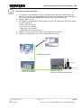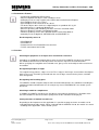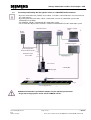
1
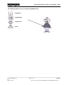
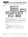
Industry Automation and Drive Technologies - SCE
Training Manual for Integrated Automation
Solutions
Totally Integrated Automation (TIA)
MODULE E12
VISION SENSOR Shape Checking
with SIMATIC S7-300F-2 PN/DP and VS120
TIA Training Document
E12
Status: 01/2010
Page 1 of 47
Module
Vision Sensor Shape Check with SIMATIC S7-300F 2PN/DP and VS120
Industry Automation and Drive Technologies - SCE
This manual was prepared for training purposes by Siemens AG for the project Siemens Automation Cooperates
with Education (SCE).
Siemens AG does not guarantee the contents of this document.
Passing on this document as well as copying it, using and communicating its contents is permitted within public
training and continued education facilities. Exceptions require the written permission by Siemens AG (Michael
Knust [email protected]).
Violators are held liable to pay damages. All rights -including translation- reserved, particularly if a patent is
granted, or a utility model or design is registered.
We wish to thank the Michael Dziallas Engineering corporation and the instructors of vocational schools as well
as all those who provided support during the preparation of this manual.
TIA Training Document
E12
Status: 01/2010
Page 2 of 47
Module
Vision Sensor Shape Check with SIMATIC S7-300F 2PN/DP and VS120
Industry Automation and Drive Technologies - SCE
PAGE
1.
Preface.....................................................................................................Fehler! Textmarke nicht definiert.
2.
Notes on using the CPU 315F-2 PN/DP .........................................................................................................7
3.
Notes on the SIMATIC VS120 components....................................................................................................7
4.
5.
6.
3.1.
Product Description ................................................................................................................................7
3.2.
Performance Features ...........................................................................................................................8
3.3.
Function..................................................................................................................................................8
3.4.
Recording and Reading Out Recognition Values in a PROFINET IO Environment...............................9
3.5.
Setting the Communication Interface of the VS120 to PROFINET ......................................................10
Starting up a project with CPU 315F-2 PN/DP and VS120...........................................................................12
4.1.
Setting Up a New Project .....................................................................................................................13
4.2.
Configuring the Hardware ....................................................................................................................15
4.3.
Assigning the Device Name .................................................................................................................23
4.4.
Inserting Blocks and FB1 and DB10 into the Project ...........................................................................25
4.5.
Function Block FB1 ..............................................................................................................................25
4.6.
Operating FB1 ......................................................................................................................................28
4.7.
FB1 Error Information...........................................................................................................................29
4.8.
Data Block DB10 ..................................................................................................................................29
4.9.
Supplementing the Symbol Table ........................................................................................................31
4.10.
FC10 Control Program .........................................................................................................................31
4.11.
Calling FC10 in OB1.............................................................................................................................33
WEB Server based operator interface of VS120 ..........................................................................................34
5.1.
Setting Up and Evaluating the Model ...................................................................................................34
5.2.
Setting up the Model Set and Evaluating the Model Number...............................................................42
Results of image evaluation in the CPU .......................................................................................................46
6.1.
Web View of the Evaluation .................................................................................................................46
6.2.
DB10 Data View ...................................................................................................................................46
6.3.
Variable Table DB_Values ...................................................................................................................47
6.4.
Symbol Table .......................................................................................................................................47
TIA Training Document
E12
Status: 01/2010
Page 3 of 47
Module
Vision Sensor Shape Check with SIMATIC S7-300F 2PN/DP and VS120
Industry Automation and Drive Technologies - SCE
The following symbols serve as a guide through Module E12:
Information
Programming
Sample Task
Notes
TIA Training Document
E12
Status: 01/2010
Page 4 of 47
Module
Vision Sensor Shape Check with SIMATIC S7-300F 2PN/DP and VS120
Industry Automation and Drive Technologies - SCE
1
PREFACE
Regarding its content, Module E12 is part of the instruction unit ’IT Communication with S7’.
Fundamentals of
STEP7 Programming
2 to 3 days Modules A
Additional Functions of
STEP7 Programming
2 to 3 days Modules B
Programming
Languages
2 to 3 days Modules C
System Simulation
with SIMIT SCE
1 to 2 days Modules G
Industrial Fieldbus
Systems
2 to 3 days Modules D
D
Frequency Converter
at SIMATIC S7
2 to 3 days Modules H
Process
Visualization
2 to 3 days Modules F
IT Communication
with SIMATIC S7
2 to 3 days Modules
E
Objective
In Module E12, the reader learns how networking and data exchange between PLCs and the vision
sensor evaluation device VS120 is set up.
As PLC, the CPU 315F-2 PN/DP and as vision sensor evaluation device the VS120 system for the
shape check are used. The SIMATIC VS120 components consist of an evaluation device with a
sensor head and an LED ring lamp. PROFINET is used for networking between the PLC and the
SIMATIC VS120.
Module E12 shows in principle the procedure for the startup, based on a brief example.
.
Prerequisites
To successfully work through Module E12, the following knowledge is assumed:
•
How to handle Windows
•
Fundamentals of PLC programming with Step7 (for example, Module A3 ‘Startup’ PLC
Programming with STEP7)
•
Fundamentals of network engineering (for example: Appendix V – Basics of Network
Engineering)
TIA Training Document
E12
Status: 01/2010
Page 5 of 47
Module
Vision Sensor Shape Check with SIMATIC S7-300F 2PN/DP and VS120
Industry Automation and Drive Technologies - SCE
Hardware and software required
1
2
3
4
5
PC, operating system Windows XP Professional with SP2 or SP3/Vista 32 Bit Ultimate and
Business/Server 2003 SP2 with 600MHz (only XP)/1 GHz and 512MB (only XP)/1 GB RAM, free
disk storage approx. 650 to 900 MB, MS Internet Explorer 6.0 and network card
Software STEP 7 V 5.4
SPS SIMATIC S7300 with CPU 315F-2 PN/DP and at least one digital input and output module.
Sample configuration:
- Power supply: PS 307 2A
- CPU: CPU 315F-2 PN/DP
- Digital inputs: DI 16x24VDC
- Digital outputs: DO 16x24VDC/0.5 A
SIMATIC VS120 evaluation device with sensor head and LED ring lamp
Ethernet connection between PC, CPU 315F-2 PN/DP and VS120
2 STEP 7
1 PC
5 Ethernet Connection
3 SIMATIC S7-300 with
CPU 315F-2 PN/DP
TIA Training Document
E12
Status: 01/2010
4 SIMATIC VS120
with sensor head and LED ring lamp
Page 6 of 47
Module
Vision Sensor Shape Check with SIMATIC S7-300F 2PN/DP and VS120
Industry Automation and Drive Technologies - SCE
2
NOTES ON USING THE CPU 315F-2 PN/DP
The CPU 315F-2 PN/DP is a CPU that is shipped with 2 integrated interfaces.
-
The first interface is a combined MPI/PROFIBUS DP interface that can be used at the
PROFIBUS DP as master or slave to connect distributed IO/field devices with very fast reaction
time.
In addition, it is possible to program the CPU here by means of an MPI or PROFIBUS DP
-
The second interface is an integrated PROFINET interface.
This allows for using the CPU as PROFINET IO controller to operate distributed IO
on PROFINET. The CPU can be programmed by means of this interface also!
Moreover, it is possible to use fail-safe IO devices on both interfaces.
-
Notes:
In module E12, the CPU 315F-2 PN/DP is used as the controller for the data exchange of a
SIMATIC RFID system on the PROFINET.
To run this CPU, a micro-memory card is required!
The addresses of the input and output modules can be parameterized at this CPU.
3
NOTES ON THE SIMATIC VS120 COMPONENTS
3.1 Product Description
The vision sensor SIMATIC VS120 is used to optically recognize and check objects applying the
incident light method. The vision sensor SIMATIC VS120 checks whether the object is the correct
one, whether it is intact, and what its position is.
The vision sensor SIMATIC VS120 supplies the following recognition values for object recognition:
• x-coordinate
• y-coordinate
• angle
• Quality values of the object being checked, number of the parts found
This object recognition data is transmitted to evaluation units in automation systems. The data is
then processed in the evaluation units of the automation systems.
The vision sensor SIMATIC VS120 is suitable for the following:
• Recognizing parts for sorting tasks
• Determining the position for Pick&Place applications
• Existence check and position check in manufacturing
• Position check for feed engineering; for example, for swing conveyors <<?>>, workpiece carriers,
circulation systems and gripper units as well as robots
• Quality control of checked objects
TIA Training Document
E12
Status: 01/2010
Page 7 of 47
Module
Vision Sensor Shape Check with SIMATIC S7-300F 2PN/DP and VS120
Industry Automation and Drive Technologies - SCE
3.2 Performance Features
• Incident light method with LED ring lamp
• Object recognition with object search and object check
• Startup by means of setup support at the PG/PC with installed Internet Explorer
• Up to 20 object checks per second
• Up to 64 objects to be checked can be stored
• To sort the objects to be checked, 2 digital outputs are provided: OK, N_OK
• Operator interface is completely Web-based
• Extensive operating and monitoring functions also in the evaluation mode
• Extensive diagnosis functions and logging functions
• Firmware update by means of the operator interface of the Web browser
• Control by means of digital I/O, PROFIBUS DP and PROFINET IO
Result output by means of
– PROFIBUS DP
– PROFINET IO
– RS232 interface of an RS232 Ethernet converter
– TCP/IP connection of the PC/PG
3.3 Function
Checking the properties of an object to be checked for correctness
64 models are provided to recognize objects to be checked. The SIMATIC VS120 checks whether
the individual characteristics of the object to be checked are shaped as the trained model is.
When specifying the recognition and evaluation area, glossy areas on the objects to be tested are to
be avoided.
Recognition principles of edges
To recognize image patterns, edges are used. These edges in the images are transitions from light to
dark or vice versa. A model is generated from the sum of edges extracted in the picture, and from
their arrangement.
Recognizing and localizing parts
The SIMATIC VS120 recognizes objects to be checked and determines the coordinates including the
rotational position and forwards them -for example, by means PROFIBUS DP- to a control system
like the S7.
Checking a model for completeness
In addition, the SIMATIC VS120 checks the objects in question for completeness. Deviations from
the trained model are detected, and the quality values of the evaluation are displayed.
Sorting functions of models in model sets
Depending on the importance of the application, it is possible to group and store 15 model sets for
evaluation with 64 possible models. When evaluated with the SIMATIC VS120, the models are sorted
-according to the application- with a control system.
TIA Training Document
E12
Status: 01/2010
Page 8 of 47
Module
Vision Sensor Shape Check with SIMATIC S7-300F 2PN/DP and VS120
Industry Automation and Drive Technologies - SCE
3.4
Recording and Reading Out Recognition Values in a PROFINET IO Environment
• By means of the Ethernet (TCP/IP) and a switch, a PC/PG is connected that is used exclusive for
the setup process.
• By means of the Ethernet and a switch, a connection exists to an automation systems with
PROFINET IO capability.
• The SIMATIC VS120 is controlled by the automation system.
• The result of the objects to be checked is read out via PROFINET IO to the automation system
Evaluation Device
PC/PG to support
setup
Power
Supply
Automation System
Power Supply Cable
Functional Ground Cable
Illumination Cable
Sensor Cable
Sensor Head
Cable DI/DO
LED Ring Light
Object
Light Barrier
Conveyor
Conveying Direction
Additional information is provided in Chapter 3 of the operating instructions
“Image Processing Systems Vision Sensor SIMATIC VS120“.
TIA Training Document
E12
Status: 01/2010
Page 9 of 47
Module
Vision Sensor Shape Check with SIMATIC S7-300F 2PN/DP and VS120
Industry Automation and Drive Technologies - SCE
3.5
Setting the Communication Interface of the VS120 to PROFINET
First, switch on the power supply of the evaluation device VS120 for the initial startup.
At the initial startup, "Factory Settings Used" appears on the LCD display.
Confirm with "OK".
The VS120 will then perform a self test:
• Checking the Ethernet connection
Press ESC
• Functional check of the sensor head
Press ESC
After completion of the self test, "Adjust" appears on the LCD display
Press OK to get to the main menu
At any additional start of the SIMATIC VS120, the evaluation device VS120 performs the following
self test:
• Checking the stored settings and model data
• Checking the Ethernet connection
• If needed, checking the connection to PROFINET IO
• If needed, checking the Ethernet RS232 converter or TCP server and to the PC/PG <<?>>
• If needed, checking whether it is possible to exchange data from and to PROFIBUS DP
• Function check of the sensor head
• If needed, checking the connection for archiving the model data
If the self test ran without a fault, the following is indicated on the LCD display: the main menu, the
display "Adjust", or the RUN menu, depending on the status at the last switch-off.
You may have to press ESC several times to get to the main menu
In addition, we navigate in the LCD display between the menus, and make entries.
"Main" Menu:
To set the VS120 to PROFINET, we have to get to the “Connect“ menu.
Place the cursor in front of Connect, and press the OK key.
TIA Training Document
E12
Status: 01/2010
Page 10 of 47
Module
Vision Sensor Shape Check with SIMATIC S7-300F 2PN/DP and VS120
Industry Automation and Drive Technologies - SCE
"Connect" Menu:
The Ethernet IP mode has to be set to PNIO.
Place the cursor in front of Ports and press the OK button
Place the cursor in front of Ethernet and press the OK button
Place the cursor in front of IP Mode and press the OK button
Place the cursor in front of PNIO and press the OK button
The evaluation device now requests a restart; press the OK button to confirm.
After the restart, the red bus error LED (BF) flashes until communication is established by means of
PROFINET between a controller and the VS120.
ESC may have to be pressed several times to get to the main menu.
All additional information for operating the evaluation device is provided in chapters 8.3, 8.4
and 9.2 of the operating instructions
“Image Processing Systems Vision Sensor SIMATIC VS120“.
TIA Training Document
E12
Status: 01/2010
Page 11 of 47
Module
Vision Sensor Shape Check with SIMATIC S7-300F 2PN/DP and VS120
Industry Automation and Drive Technologies - SCE
4
STARTING UP A PROJECT WITH CPU 315F-2 PN/DP AND VS120
Below, starting up the VS120 in a project is described.
As SIMATIC S7-300 Station, the CPU 315F-2 PN/DP is used.
In the CPU’s control program, a data structure has to be generated by means of a function block call
(FB1) with data block (DB10).
The data structure looks like this:
FB1
for VS120
DB10
Result of the form
checl
Instance DB1
of FB1
All additional information is provided in Chapter 10 of the operating instructions
“Image Processing Systems Vision Sensor SIMATIC VS120“.
TIA Training Document
E12
Status: 01/2010
Page 12 of 47
Module
Vision Sensor Shape Check with SIMATIC S7-300F 2PN/DP and VS120
Industry Automation and Drive Technologies - SCE
4.1
Setting Up a New Project
1. The central tool in STEP 7 is the ’SIMATIC Manager’. It is called here with a double click (→
SIMATIC Manager)
2. STEP7 programs are managed in projects. We are now setting up such a project
(→ File → New)
3. Now, the project is assigned the ’Name’ ’VS120’ (→ VS120 → OK)
TIA Training Document
E12
Status: 01/2010
Page 13 of 47
Module
Vision Sensor Shape Check with SIMATIC S7-300F 2PN/DP and VS120
Industry Automation and Drive Technologies - SCE
4. Next, highlight your project and insert an ’Industrial Ethernet Subnet’.
(→ VS120 → Insert → Subnet → Industrial Ethernet).
5. Now, a ’SIMATIC 300 Station’ is inserted (→ Insert → Station → SIMATIC300 Station)
TIA Training Document
E12
Status: 01/2010
Page 14 of 47
Module
Vision Sensor Shape Check with SIMATIC S7-300F 2PN/DP and VS120
Industry Automation and Drive Technologies - SCE
4.2 Configuring the Hardware
6. With a double click, open the configuration tool for the ’Hardware’. (→ Hardware)
7. Open the hardware catalog by clicking on the symbol '
’. (→
)
Insert the ’Mounting Channel’ with a double click (→ SIMATIC 300 → RACK-300
→ Mounting Channel).
Note:
Then, a configuration table is displayed automatically for setting up Rack 0.
TIA Training Document
E12
Status: 01/2010
Page 15 of 47
Module
Vision Sensor Shape Check with SIMATIC S7-300F 2PN/DP and VS120
Industry Automation and Drive Technologies - SCE
8. Now, from the hardware catalog select all modules that are also inserted in your actual rack and
place them in the configuration table. To this end, click on the name of the respective module,
hold the mouse key and drag it to a line in the configuration table.
We start with the power supply ’PS 307 5A’ (→ SIMATIC 300 → PS-300 → PS 307 5A)
Note:
If your hardware differs from the one shown here, simply select the corresponding modules in the
catalog and insert them in your rack. The order numbers of the individual modules that are also
inscribed on the components, are shown in the footer of the catalog.
TIA Training Document
E12
Status: 01/2010
Page 16 of 47
Module
Vision Sensor Shape Check with SIMATIC S7-300F 2PN/DP and VS120
Industry Automation and Drive Technologies - SCE
9. Next, we drag the ’CPU 315F-2 PN/DP’ to the second slot.
The CPU’s order number and the version are provided on the front of the CPU.
(→ SIMATIC 300 → CPU-300 → CPU 315F-2 PN/DP → 6ES7 315-2FH13-0AB0 → V2.6)
10. When entering the CPU, the window below is displayed. In this window, do the following: assign
to the CPU 315F-2 PN/DP an ’IP Address’, specify the ’Subnet screen form’ and select the
’Ethernet’ that is already set up. Optionally, a ’Router Address’ can be selected for networkoverarching communication. Confirm your inputs with ’OK’ (→ IP Address: 192.168.0.100 →
Subnet screen form: 255.255.255.0 → Ethernet(1) → Don’t use a router→ OK)
TIA Training Document
E12
Status: 01/2010
Page 17 of 47
Module
Vision Sensor Shape Check with SIMATIC S7-300F 2PN/DP and VS120
Industry Automation and Drive Technologies - SCE
Notes regarding networking on the Ethernet (additional information is provided in Appendix V
of the training manual):
MAC address:
The MAC address consists of a permanent and a variable part. The permanent part ("Basic MAC
address") identifies the manufacturer (Siemens, 3COM, ...). The variable part of the MAC address
differentiates the different Ethernet stations and should be assigned globally unique. On each module,
a MAC address specified by the factory is inscribed.
Value range for the IP address:
The IP address consists of 4 decimal numbers in the value range 0 to 255, separated by a period; for
example: 141.80.0.16
Value range for the subnet screen form:
This screen form is used to establish whether a station or its IP address belongs to the local subnet,
or can be reached only by means of a router.
The subnet screen form consists of 4 decimal numbers in the value range 0 to 255, separated by a
period; for example: 255.255.0.0
The 4 decimal numbers of the subnet screen form have to contain -in their binary representationfrom the left a series of gapless values "1" and from the right a series of gapless values "0"..
The values "1" determine the area of the IP address for the network number. The values "0"
determine the area of the IP address for the station address.
Example:
Correct values:
255.255.0.0 Decimal = 1111 1111.1111 1111.0000 0000.0000 0000 binary
255.255.128.0 Decimal = 1111 1111.1111 1111.1000 0000.0000 0000 binary
255.254.0.0 Decimal = 1111 1111.1111 1110.0000 0000.0000.0000 binary
Incorrect value:
255.255.1.0 Decimal = 1111 1111.1111 1111.0000 0001.0000 0000 binary
Value range for the address of the gateway (router):
The address consists of 4 decimal numbers in the value range 0 to 255 separated by a period; for
example, 141.80.0.1.
Relationship of the IP addresses, router address and subnet screen form:
The IP address and the gateway address must differ only at those positions where a "0" is shown in
the subnet screen form.
Example:
You entered the following: for subnet screen form 255.255.255.0; for IP address 141.30.0.5 and for
router address 141.30.128.1.
The value for the IP address and the gateway address is to differ only in the 4th decimal number.
However, in the example, the 3rd position already differs.
In the example, we have to alternatively change:
- the subnet screen form to: 255.255.0.0 or
- the IP address to: 141.30.128.5 or
- the gateway address to: 141.30.0.1
TIA Training Document
E12
Status: 01/2010
Page 18 of 47
Module
Vision Sensor Shape Check with SIMATIC S7-300F 2PN/DP and VS120
Industry Automation and Drive Technologies - SCE
11.
Next, we drag the input module for 16 inputs to the 4th slot. The module’s order number is
inscribed on the front. (→ SIMATIC 300 → DI-300 → SM 321 DI16x24VDC).
Note:
Slot 3 is reserved for interface modules and remains empty for that reason. The module’s order
number is shown in the footer of the catalog.
TIA Training Document
E12
Status: 01/2010
Page 19 of 47
Module
Vision Sensor Shape Check with SIMATIC S7-300F 2PN/DP and VS120
Industry Automation and Drive Technologies - SCE
12. Then, we drag the output module for the 16 outputs to the 5th slot. The module’s order number is
inscribed on the front. (→ SIMATIC-300 → DO-300 → SM 322 DO16x24VDC/0.5A).
Note:
The module’s order number is shown in the footer of the catalog.
13. Now, we have to change the PROFINET device name to PN-IOx100.
Select ’PN-IO’ with a double click (→ PN-IO,→ PN-IOx100,→ OK)
TIA Training Document
E12
Status: 01/2010
Page 20 of 47
Module
Vision Sensor Shape Check with SIMATIC S7-300F 2PN/DP and VS120
Industry Automation and Drive Technologies - SCE
14. Then, drag the PROFINET IO System (100) module tier <<?>> toward the right, and from the
folder PROFINET IO add the SIMATIC VS100 module VS120 by dragging it to the tier.
If module VS120 should not be available for selection, it has to be added by a data carrier by
means of the menu “Options“ Install GSD files.
15. Double click on the inserted module and change the device name to VS120x120 and the IP
address to 192.168.0.120.
TIA Training Document
E12
Status: 01/2010
Page 21 of 47
Module
Vision Sensor Shape Check with SIMATIC S7-300F 2PN/DP and VS120
Industry Automation and Drive Technologies - SCE
16. Now double click on the control byte of the inserted module and change the address of the inputs
to 10 and of the outputs to 20.
auf 20
Hardware View
17. By clicking on '
TIA Training Document
E12
Status: 01/2010
’, the hardware configuration is stored and compiled.
Page 22 of 47
Module
Vision Sensor Shape Check with SIMATIC S7-300F 2PN/DP and VS120
Industry Automation and Drive Technologies - SCE
4.3
Assigning the Device Name
18. Highlight module VS120 and then select, via the menu “Destination system“, at Ethernet ’Assign
device name’.
Note:
A precondition for this is that the PG/PC interface is set to TCP/IP and the network card for the PC is
configured correctly. For example, IP address 192.168.0.99, subnet 255.255.255.0 and router
address -.-.-.- (refer to Module E02).
19. Highlight the VS100 module and then click on the button “Assign name“. Close the window.
TIA Training Document
E12
Status: 01/2010
Page 23 of 47
Module
Vision Sensor Shape Check with SIMATIC S7-300F 2PN/DP and VS120
Industry Automation and Drive Technologies - SCE
20. By clicking on '
’, we can now load the hardware configuration into the PLC. The operating
mode switch should be on Stop! (→
).
(After the hardware is loaded into the CPU, the red BF LED on the VS120 goes out)
21. Close the hardware configuration.
TIA Training Document
E12
Status: 01/2010
Page 24 of 47
Module
Vision Sensor Shape Check with SIMATIC S7-300F 2PN/DP and VS120
Industry Automation and Drive Technologies - SCE
4.4
Inserting Blocks and FB1 and DB10 into the Project
From the template directory or from the Image Processing System SIMATIC VS120 V2.1 CD from
the directory "Function Blocks“, de-archive and open the library VS120-2.
Add FB1 and DB10 to the block folder of the project.
Close the library.
Note:
Instead of library VS120-2, we can also de-archive the example program VS120_Examples. The file
Vs120_Examples.zip is located on the Image Processing System SIMATIC VS120 V2.1 CD in the
directory “Examples“, subdirectory "SIMATIC“
4.5
Function Block FB1
For a simpler handling of the functions of Vision Sensor SIMATIC VS12, the function block FB1 is
provided for IO operations.
FB1 facilitates software-engineering integration into the control program.
Tasks of FB1
• Selecting a model or model set
• Reading the result data and storing it in DB10
(DB10 is included in the documentation package)
• Operating the control and status interface (triggering, result bits, ...)
• Transmitting the delay time of the trigger
• Reading out error indications
TIA Training Document
E12
Status: 01/2010
Page 25 of 47
Module
Vision Sensor Shape Check with SIMATIC S7-300F 2PN/DP and VS120
Industry Automation and Drive Technologies - SCE
FB1 Input Parameters
Declaration
Data Type
Description
Address of the control byte in the SIMATIC VS120
interface that is entered under the Connection
Control.
This parameter has to be wired.
Address of the status byte of the SIMATIC VS120
interface that is entered under Connection Control
Start address of the user data interface "Send“ of the
SIMATIC VS120/"Receive“ of the PLC
Start address of the user data interface "Receive“ of
the SIMATIC VS120/ "Send“ of the PLC
Model number 1 to 15.
Note: For model changes, the DISA bit has to be set
Disable: disables manual key operation
Reset: Reset error evaluation device or FB error.
Note: Works also without setting the DISA bit
Trigger: Image pickup and starting the evaluation
transferofofthe
thetrigger
triggerdelay
delaytime
timetotothe
the
Delay time: transfer
SIMATIC
SIMATIC VS120
VS120 in
in us
us (value range: 0 to 9.999.999us).
(value range: 0 to 9.999.999us)
Note:
The
a multiple
of 50usofwith
off
Note:
The value
delay is
value
is a multiple
50usrounding
with
Notedelay
limits of 0us or 50us. For example, 49us becomes
rounding
limits of50us..
0 or 50us. For example, 49us
0us,
65usoff
becomes
become 0us. 65us become 50us.
Receive: Receive area for the result values
Permissible are only data block areas and the data
type BYTE. This parameter has to be wired and the
data block has to be at least as large as the maximum
result to be expected.
Notes
____________________________________________________________________________
____________________________________________________________________________
____________________________________________________________________________
____________________________________________________________________________
____________________________________________________________________________
____________________________________________________________________________
TIA Training Document
E12
Status: 01/2010
Page 26 of 47
Module
Vision Sensor Shape Check with SIMATIC S7-300F 2PN/DP and VS120
Industry Automation and Drive Technologies - SCE
FB1 Output Parameters
Notes
____________________________________________________________________________
____________________________________________________________________________
____________________________________________________________________________
____________________________________________________________________________
____________________________________________________________________________
____________________________________________________________________________
____________________________________________________________________________
____________________________________________________________________________
TIA Training Document
E12
Status: 01/2010
Page 27 of 47
Module
Vision Sensor Shape Check with SIMATIC S7-300F 2PN/DP and VS120
Industry Automation and Drive Technologies - SCE
4.6
Operating FB1
Model Selection
• To select a model, the DISA bit has to be set to 1.
• The desired model number is set up at FB1 input MODEL.
• The model change is completed when the TRD and RDY bit changes from FALSE to TRUE. The
model number that was set up is placed on output MODEL_OUT.
• As long as no model was transmitted, 0 is read out at output MODEL_OUT.
• The output MODEL_OUT changes to 0 as soon as the DISA bit is reset.
• If MODEL = 0, the model that was selected last is retained. 0 is read out at output MODEL_OUT.
Reset
• When errors are reset, SIMATIC VS120 module errors (IN_OP = 0) and the FB1 transmission
errors are reset.
Triggering
• With the trigger input at FB1, image evaluation with the SIMATIC VS120 can be activated.
• For mixed operation "Controlling by means of PROFIBUS DP and triggering by means of DI/DO“
the trigger signal can be connected directly to the evaluation device VS120. The FB1 parameter
TRG remains free in this case.
Transmitting Delay Time
• The time delay for hardware oriented trigger delays is set up at the FB1 parameter DELAY. With
the delay time parameter, the value for the hardware oriented trigger supply can be specified.
Reading and transmitting result data
• The FB1 is always ready to receive.
• After an OK or N_OK evaluation, the result data is read out.
• The data is valid when bit NDR changes from 0 to 1.
• With the setup support under "Connections - Register Output" we are setting how many
Sub-ROIs (regions of interest) are transmitted.
TIA Training Document
E12
Status: 01/2010
Page 28 of 47
Module
Vision Sensor Shape Check with SIMATIC S7-300F 2PN/DP and VS120
Industry Automation and Drive Technologies - SCE
4.7
FB1 Error Information
If an error occurs, ERROR = 1 is set.
The exact cause for the error is indicated in ERRCODE.
Error information
• 0000: No error
• 1xyz: Internal FB1error
• 2xyz: Evaluation device error
• 8xyz: Error indications of internal SFCs
Explanation
No error
Impermissible model number (parameter model). The values 1 to 15 are
permissible
Impermissible reveive area. Only data type BYTE is permissible
Impermissible data area. Only data blocks are permissble
The receive area does not exist (data block not available)
The receive area is too short
The receive area is write protected
The delay value is outside the permissible range of 0 to 9.999.999us
Selected model number is not trained
Transfer of SFC14 and SFC 15 error indications
No module is configured for the specified logical base address
An access error was detected during the access to the IO
System error at the external PROFIBUS DP interface
4.8
Data Block DB10
Tasks of DB10
DB10 is laid out for the structured acceptance/storage of the data from one Main ROI and a
maximum of 16 Sub-ROIs. In the setup support, the number of Sub-ROIs is set in Connections –
Register Output.
.
TIA Training Document
E12
Status: 01/2010
Page 29 of 47
Module
Vision Sensor Shape Check with SIMATIC S7-300F 2PN/DP and VS120
Industry Automation and Drive Technologies - SCE
Structure of the DB10
(DB10 has a size of 246 bytes and can accommodate 16 SubROIs)
TIA Training Document
E12
Status: 01/2010
Page 30 of 47
Module
Vision Sensor Shape Check with SIMATIC S7-300F 2PN/DP and VS120
Industry Automation and Drive Technologies - SCE
4.9
Supplementing the Symbol Table
Open the symbol table and enter the following symbol assignments.
Save and close the symbol table.
4.10
FC10 Control Program
In FC10, we now generate the control program for the Vision Sensor Module VS120.
Generate FC10.
TIA Training Document
E12
Status: 01/2010
Page 31 of 47
Module
Vision Sensor Shape Check with SIMATIC S7-300F 2PN/DP and VS120
Industry Automation and Drive Technologies - SCE
The input/output addresses of the VS120 (hardware) have to be entered at the first four input
parameters of FB1.
With input I0.0, the command for image pickup and for starting the evaluation is executed.
With input I0.1, the error is reset if there is an error.
With input I0.2, operating the VS120 manually is disabled.
At input parameter RECV, DB10 is specified as ANY P#DB10.DBX1.0 BYTE 245.
In DB10, data is entered starting with Byte 1.
By means of the inputs Q4.0 to Q4.6, the VS120 status information is displayed.
FB1 is called on Network 1
Additional information is provided in Chapter 10.6 of the operating instructions
"Image Processing System Vision Sensor SIMATIC VS120“.
TIA Training Document
E12
Status: 01/2010
Page 32 of 47
Module
Vision Sensor Shape Check with SIMATIC S7-300F 2PN/DP and VS120
Industry Automation and Drive Technologies - SCE
4.11
Calling FC10 in OB1
Double click on OB1.
Enter symbolic name and symbol comment.
Confirm with OK
Enter Network 1.
Save and close OB1.
We now can load the program into the CPU.
TIA Training Document
E12
Status: 01/2010
Page 33 of 47
Module
Vision Sensor Shape Check with SIMATIC S7-300F 2PN/DP and VS120
Industry Automation and Drive Technologies - SCE
5.
WEB SERVER BASED OPERATOR INTERFACE OF VS120
5.1 Setting Up and Evaluating the Model
Open the Internet browser.
As link, enter the IP address 192.168.0.120 of the VS120.
To set the language, click on the German flag.
TIA Training Document
E12
Status: 01/2010
Page 34 of 47
Module
Vision Sensor Shape Check with SIMATIC S7-300F 2PN/DP and VS120
Industry Automation and Drive Technologies - SCE
Click on Set up Sensor.
On the left of the interface, you will see a selection of tasks in the form of buttons. Activate the
desired task with a mouse click on the corresponding button. The associated dialog will then be
displayed on the right side of the interface.
The Web server based interface for Vision Sensor SIMATIC VS120 provides the following
dialog fields for image evaluation:
• Set up
• Connections
• Training
• Evaluating
• Options
• Info
• Managing
• Stop
A traffic light is located below the task buttons that shows you at a glance the current operating mode
of the evaluation device VS120.
The traffic light can display the following states:
• Green:
• Yellow:
• Red:
TIA Training Document
E12
Status: 01/2010
Evaluation mode VS120 with result output
STOP including setup and training
Error
Page 35 of 47
Module
Vision Sensor Shape Check with SIMATIC S7-300F 2PN/DP and VS120
Industry Automation and Drive Technologies - SCE
Click on the button Set up.
Here, we specify the parameters for image pickup and image evaluation.
To create patterns that can be recognized, edges -that is, the transition from light to dark or vice
versa- of the image are used. Although the algorithm extracts the edges automatically, the user has
to provide for an image rich in contrasts through optimum exposure; i.e., to generate models that are
recognizable, creating an image that is rich in contrasts through optimum exposure is a precondition.
Automatic exposure time should be selected only if the object to be checked is not moving.
Selecting the accuracy is based on the size of the search ranges and on the detectable changes of
the object to be checked. Parts in the image are searched for pyramidically.
We start with a rough search with low resolution, and conclude with a detail search with a high
resolution.
The accuracy influences the rough and detailed search.
The higher the checking accuracy, the longer the evaluation takes.
Additional information is provided in Chapter 4 of the operating instructions
"Image Processing System Vision Sensor SIMATIC VS120“.
TIA Training Document
E12
Status: 01/2010
Page 36 of 47
Module
Vision Sensor Shape Check with SIMATIC S7-300F 2PN/DP and VS120
Industry Automation and Drive Technologies - SCE
Now click on the button Connections.
Then click on the tab Integration or on the button Continue.
As Trigger, set the source PROFINET IO.
At Connection, set the output, OK/N_OK, and controller PROFINET IO.
Click on Accept.
Next, click on the button Training.
TIA Training Document
E12
Status: 01/2010
Page 37 of 47
Module
Vision Sensor Shape Check with SIMATIC S7-300F 2PN/DP and VS120
Industry Automation and Drive Technologies - SCE
Then click on the button Continue, set the parameters and draw a circular ROI (Region of Interest)
around the part.
Click on the button Continue
Additional information about the parameters is provided in Chapter 4.3 of the operating instructions
"Image Processing System Vision Sensor SIMATIC VS120“.
Under the tab Edges, interfering or unimportant edges can be removed.
TIA Training Document
E12
Status: 01/2010
Page 38 of 47
Module
Vision Sensor Shape Check with SIMATIC S7-300F 2PN/DP and VS120
Industry Automation and Drive Technologies - SCE
Under the tab Test, the trained part is tested.
Click on the button Continue.
TIA Training Document
E12
Status: 01/2010
Page 39 of 47
Module
Vision Sensor Shape Check with SIMATIC S7-300F 2PN/DP and VS120
Industry Automation and Drive Technologies - SCE
Under the tab Save, save the model with the name Part1.
Now click on the button Evaluate and start the evaluation mode.
Set the CPU to Run and start the image evaluation with "Start“ (I0.0).
TIA Training Document
E12
Status: 01/2010
Page 40 of 47
Module
Vision Sensor Shape Check with SIMATIC S7-300F 2PN/DP and VS120
Industry Automation and Drive Technologies - SCE
Evaluation result: Faulty part with the Number 1 is too large and milling is crooked.
Evaluation result: Faulty part with Number 16 instead of Number 1
TIA Training Document
E12
Status: 01/2010
Page 41 of 47
Module
Vision Sensor Shape Check with SIMATIC S7-300F 2PN/DP and VS120
Industry Automation and Drive Technologies - SCE
5.2 Setting Up the Model Set and Evaluating the Model Number
Several models are to be trained and combined into a set.
Train parts 2 to 5.
TIA Training Document
E12
Status: 01/2010
Page 42 of 47
Module
Vision Sensor Shape Check with SIMATIC S7-300F 2PN/DP and VS120
Industry Automation and Drive Technologies - SCE
Parts 1 to 5 are to be combined into one model set.
Click on the button Options.
In the tab Extras under Multi-Model Use: select ON.
Highlight Part1 to Part5.
Save Part1 with the names
Click on the button Accept.
All additional information about operating the Web server based interface is provided in
Chapter 9.3 of the operating instructions "Image Processing System Vision Sensor SIMATIC
VS120“.
TIA Training Document
E12
Status: 01/2010
Page 43 of 47
Module
Vision Sensor Shape Check with SIMATIC S7-300F 2PN/DP and VS120
Industry Automation and Drive Technologies - SCE
Now click on the button Evaluate and start the evaluation mode.
Set the CPU to Run and start image evaluation with “Start“ (I0.0).
The work pieces are recognized.
TIA Training Document
E12
Status: 01/2010
Page 44 of 47
Module
Vision Sensor Shape Check with SIMATIC S7-300F 2PN/DP and VS120
Industry Automation and Drive Technologies - SCE
Even if the number is faulty, a parts assignment is still made by means of the shape.
TIA Training Document
E12
Status: 01/2010
Page 45 of 47
Module
Vision Sensor Shape Check with SIMATIC S7-300F 2PN/DP and VS120
Industry Automation and Drive Technologies - SCE
6
RESULTS OF IMAGE EVALUATION IN THE CPU
6.1 Web View of the Evaluation
6.2 DB10 Data View
The result of the image evaluation is stored in DB10
TIA Training Document
E12
Status: 01/2010
Page 46 of 47
Module
Vision Sensor Shape Check with SIMATIC S7-300F 2PN/DP and VS120
Industry Automation and Drive Technologies - SCE
6.3 Variable Table DB_Values
6.4 Symbol Table
TIA Training Document
E12
Status: 01/2010
Page 47 of 47
Module
Vision Sensor Shape Check with SIMATIC S7-300F 2PN/DP and VS120