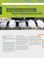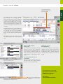
1
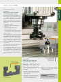
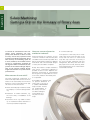
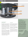
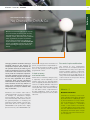
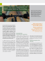
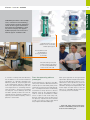
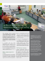
HEIDENHAIN Issue 49 + 9/2008 News from the World of HEIDENHAIN Controls 4 A Sense of Feeling for Accuracy and Efficiency 8 11 5-Axis Machining: Getting a Grip on the Accuracy of Rotary Axes KinematicsOpt: No Chance for Drift & Co. Editorial Editorial Dear Klartext Reader, Encoders from HEIDENHAIN make machines more accurate – as linear encoders and angle encoders directly on the machine, or in the form of touch probes for tools and workpieces. An even greater benefit can be gained with the TNC controls from HEIDENHAIN: “A Sense of Feeling for Accuracy and Efficiency” and “KinematicsOpt: No Chance for Drift & Co” will certainly convince you. A new section focuses on reality: With the title “Are you familiar with this function?” we outline practical TNC functions to simplify or significantly accelerate your tasks. The editorial staff of Klartext wishes you informative reading! AMB 2008 Sep. 9 - 13, 2008 the AMB. Here HEIDENHAIN shows the KinematicsOpt feature, which makes it possible to easily measure the tilting accuracy of rotary axes. HEIDENHAIN show places machine tool accuracy on center stage In addition, at several iTNC programming stations our application experts will be available to demonstrate the newest features of the control. The motto of the HEIDENHAIN exhibition at this year’s AMB trade show is “HEIDENHAIN shows the way to precision.” Demo units and presentations will help illustrate the differences between machining on machine tools equipped with linear encoders – bringing dramatically higher positioning precision and higher production efficiency – and machines that operate without them. The accuracy of 5-axis machines with rotary and swivel axes is also a topic at The new touch probes are also in focus. With its TS 740, HEIDENHAIN will present a high-accuracy infrared touch probe for very demanding 3-D measuring tasks on machine tools or measuring machines. The device operates with a piezo sensor and features a repeatability of better than 0.3 µm. The TS 444 is a version with smaller dimensions that, like its larger cousin, is also a 3-D touch probe with infrared transmission of the trigger signal. The TS 444 needs no batteries. The power supply consists of integrated capacitors charged from a small wind turbine driven by the compressed air of the machine. Visit us! h 4.E12 t o o B 4 l Hal Communications Linear and Angular Encoders Digital Readouts for Manually Operated Machine Tools Accuracy of Machine Tools Controls Image Page 4: Stock.xchng.Kliverap Page 17: Synthes All other images © DR. JOHANNES HEIDENHAIN GmbH Info Programming with smarT.NC DCM Dynamic Collision Monitoring/ KinematicsOpt Touch probes Anwendungen Contents Klartext + Issue 49 + 09/2008 ARTEXT interactive KL Check out our more en well, with ev e-magazine as ations, im an formation, in nd ou gr ck ba a look at owledge. Take and expert kn t ain.de/klartex www.heidenh HEIDENHAIN controls together with HEIDENHAIN touch probes – an unbeatable combination. Page 4 Touch Probes A Sense of Feeling for Accuracy and Efficiency 4 Applications 5-Axis Machining: Getting a Grip on the Accuracy of Rotary Axes 8 Software KinematicsOpt: No Chance for Drift & Co. 11 Controls Special Functions of the iTNC 530: Tool-Oriented Machining (TOM) 14 The Real World iTNC 530 – Application for Innovative Medical Technology HEIDENHAIN controls used at SYNTHES in the medical technology sector. Page 16 16 Training All-Round Support for CNC Apprentice and Advanced Training 18 Service HEIDENHAIN Service Product Information − 40 Years of Service Know-How Available Online! 19 Production Publisher DR. JOHANNES HEIDENHAIN GmbH Post box 1260 83292 Traunreut, Germany Tel: +49 8669 31-0 HEIDENHAIN on the Internet: www.heidenhain.de Editor Frank Muthmann Fax: +49 8669 31-1888 E-mail: [email protected] KLARTEXT on the Internet: www.heidenhain.de/klartext Layout and Typesetting Expert Communication GmbH Richard-Reitzner-Allee 1 85540 Haar, Germany Tel: +49 89 666375-0 E-mail: [email protected] www.expert-communication.de Touch Probes Insects feel their way through life. Their antennae register the environment, assess hazards, search for and evaluate objects and thus secure survival. What has been happening for thousands of years in Nature was only hesitantly learned by machine tools. A Sense of Feeling for Accuracy and Efficiency Despite initial scepticism, many machine tools cannot now be imagined without touch probes. The sensitive helpers create technological and economic advantages over the competition – provided that the symbiosis between control and touch probe functions. Only the combination of HEIDENHAIN touch probes with HEIDENHAIN controls guarantees particularly high accuracy. Elementary. Save time, increase quality Decisive. Fine synchronization between control and touch probe Machine tool experts have known it for a long time: both workpiece touch probes as well as tool touch probes help to reduce setup times, increase utilization times of machines and improve the dimensional accuracy of finished workpieces. Decisive for their success are the high accuracy levels of the touch probes and their efficient use, which must claim as little time as possible. Exact coordination between the touch probe and the control, including the whole range of components and functions, is therefore of particular significance. Operators of HEIDENHAIN controls appreciate the combination of convenient operation, powerful functions and highly developed technology that together enable a high level of contour fidelity and dimensional accuracy. Optimal results can be expected from machines whose entire control loops are implemented with coordinated components from HEIDENHAIN: This includes the control, a complete electronics package, the drives and also the linear and angle encoders. For the sake of consistency, no compromises should be made in connection with the touch probes either! There are very good reasons for this: +HEIDENHAIN controls make available countless practical functions based on workshop reality and optimally coordinated to the various HEIDENHAIN touch probes. This is shown by the diversity of cycles available on the controls, ranging from calibration of touch probes via simple cycles for setup and datum setting to programmed measuring and testing during machining. All of this is simply documented in the “Touch Optimal coordination between HEIDENHAIN touch probes... Probe Cycles” User's Manual within the TNCguide, for downloading from www.heidenhain.de Services and Documentation TNCguide. +Especially demanding measuring tasks can also be implemented: with the aid of additional software, free-form surfaces can be measured directly on the machine. Machining errors are detected immediately and can still be corrected during setup. Even More Accuracy via Kinematics Optimization The KinematicsOpt TNC function helps to further increase machining accuracy of 5-axis machines: In this case it concerns the perfect coordination of the control to the machine kinematics. For more information about this topic, see the KLARTEXT article on page 11 Klartext + Issue 49 + 09/2008 +If especially tricky measuring and testing tasks have to be carried out in connection with a HEIDENHAIN control, the HEIDENHAIN hotline is there to help with its extensive wealth of knowledge. Anwendungen Touch Probes +HEIDENHAIN‘s tradition of providing highly accurate encoders for machine tools also applies to touch probes. The sensors function wearfree and generate trigger signals of the highest quality, which are optimally evaluated by HEIDENHAIN controls (signal propagation times, for example, influence the probe repeatability of the 3-D touch probe). ... and HEIDENHAIN controls. TNC cycle: Setting the datum for the aligned workpiece. TNC cycle: Workpiece measurement. What is... ? Probe accuracy The probe accuracy specifies the error resulting from probing a test component from various directions at 20 °C ambient temperature. The probe accuracy also includes the effective ball radius. The effective ball radius is calculated from the actual ball radius and the stylus deflection required to produce the trigger signal. This also includes stylus bending. Probe repeatability Probe repeatability is the dispersion of the results derived from repeated probing of a test component from the same direc- tion. Influence of the styli: Stylus length and stylus material significantly influence the trigger characteristics of a 3-D touch probe. Styli from HEIDENHAIN ensure a probing accuracy grade of better than ±5 µm. Touch Probes Application oriented. Suitable technologies for varied demands As well as the ideal combination of a HEIDENHAIN control with HEIDENHAIN touch probes, selection of the right technology is also the key to success. Fine matching is primarily possible when the optimal touch probe is available for specific applications. Workpiece Touch Probes For series production, machines with automatic tool changers are practically standard. Time-consuming, manual fitting of the spindle or disruptions to machining are unthinkable. A workpiece touch probe must therefore be just as easily exchangeable from the magazine as a tool is. All requirements clearly defined: +Because touch probes must guarantee unobstructed workpiece machining for series production, their functionality must be absolutely reliable. The TS 440, TS 444 and TS 640 touch probes are thus equipped with an optical sensor. The advantage: the sensor works without wear and therefore has long-term dependability. +When using a tool changer, connection via cable is of course not possible. The triggering signal is therefore transmitted via infrared to the NC. Tool touch probes HEIDENHAIN also listened to the various demands made by operators, and offers two technologies regarding tool touch probes. When tools are particularly small or if materials sensitive to breakage are used, the TL Laser System is especially suitable. The contact-free measuring method by laser beam enables you to check even the smallest tools rapidly, reliably and without collision. Because the tool is measured at rated speed, errors on the tool, spindle An interesting technology shows that the development of new touch probes is oriented to practical and economic criteria. The TS 444 is without batteries and kills two birds with one stone: an air turbine generator creates electrical energy that is stored in high performance capacitors. Compressed air that is supplied through the spindle drives the turbine. The compressed air can also be used for cleaning the workpiece. The capacitors are charged very quickly, and workpiece cleaning occurs with the same operation, so ancillary time is reduced even further! Some applications have demands in terms of accuracy that are even greater than usual. In this case, use of the TS 740 is recommended. Instead of an optical sensor, a highly precise pressure sensor creates the triggering signal. Probing requires only low levels of force – an important prerequisite for particularly high probe accuracy and repeatability. Battery-free power supply with integrated air turbine generator via central compressed air supply TS 444 workpiece touch probe Highly precise pressure sensor Control and measuring technology are best from a single supplier. That leads to optimal results. and holder are detected and corrected directly. The measuring result is oriented to operating conditions and is therefore especially accurate. If normal or larger tools are used, the TT 140 – a 3-D touch trigger probe − is suitable. For specification of the exact tool dimensions, a disk-shaped probing element is deflected by probing. An optical sensor then creates a triggering signal - reliably and without wear. Whichever tool touch probe is used: a measuring process normally consists of several steps. These of course do not need to be manually performed or programmed. Instead, TS 740 workpiece touch probe measuring cycles measure tool lengths and diameters, inspect the form of the individual teeth and check for tool wear or breakage. The control automatically saves the results of measurement in the tool table. This is very fast and uncomplicated. Under program control, the NC control positions the tool and starts the measuring cycle. In order to secure constant production quality, cyclical measurements are recommended, either before machining or Klartext + Issue 49 + 09/2008 Anwendungen Touch Probes between machining steps. Uncritical. Rapid amortization with high levels of production quality. It sounds good: ancillary times down, machine operation times up and at the same time, quality optimization. If this evaluation does not suffice, then facts are needed that withstand economic inspection. And that works best with an amortization calculation. An example − a task: Align the workpiece blank parallel to the axes. Set the reference point in the machining plane at a corner. In the tool axis, set the reference point on the surface of the workpiece blank. The time saved: If this setup process is performed with a TS 3-D touch probe system from HEIDENHAIN, the time saved is approx. 4 minutes or approx. 72 %. Meaning that if this setup process is carried out once a day, you save over € 1,000 in one year with 220 workdays (at an hourly machine rate of € 70). Tip: Repeat the calculation with figures from your production experiences. If the advantages gained from accuracy and the reduction in rework and scrap are considered, then an investment in a HEIDENHAIN touch probe really proves its worth, especially for series production. Optical contact-free tool measurement Conclusion. Stretch out your antennae and make contact with us. With the combined use of HEIDENHAIN touch probes and HEIDENHAIN controls, best results can be expected from the symbiosis between accuracy and efficiency. For example: Wear-free and dependable tool measurement via disk-shaped TT 140 probing element +Reduction of ancillary times and increased production quality creates competitive advantages +In terms of functionality and technology, control and touch probes are perfectly matched TL tool touch probe +The range of touch probes offered is oriented according to the typical demands of diverse applications Ask for information directly from HEIDENHAIN. Contact: [email protected] Application 5-Axis Machining: Getting a Grip on the Accuracy of Rotary Axes In contrast to conventional 3-axis machines, 5-axis machining has completely new demands in terms of axis accuracy. It is not only a question of the precision of individual axes here, but of their accuracy in the working space. As a result, however, the number of error sources is significantly increased by the higher number of mechanical components in the machine design. Depending on the specific machine design, angle measurement is of particular importance here. What sources of error exist? The many mechanical components of a machine are all possible sources of errors. These are all stressed by the enormous dynamics of the working processes. Typical causes for inaccuracies are +Wear caused by high mechanical loads, for example, or collisions during machining +Elasticities in transfer elements, e.g. the worm shaft, or instabilities of the bearings +Geometric errors e.g. radial eccentricity of mechanical transfer elements or incorrectly installed components How can sources of error be avoided or reduced? During the design of a machine, sources of error in connection with the rotary axes should be ruled out as far as possible. As a part of the kinematic influences, different mechanical and control-oriented designs of rotary axes should be compared. Rotary axes feature complex mechanics with various components subjected to possible sources of error. Optimal compensation would have as a prerequisite the recognition of all possible error sources for every situation. And exactly that is not possible. A possibility for getting a grip on position deviations of rotary axes is the use of a suitable HEIDENHAIN angle encoder. For better understanding of the effect, here are two basic strategies for the design of rotary axes in control loops: +“Semi-Closed Loop” If the position of the rotary axis is measured solely via the rotary encoder on the motor, then we refer to a “semi-closed loop”. Not only is the lack of accuracy of the motor encoder significant with this arrangement, but many other errors also play a part such as wear, elasticity deviations and geometric errors of the mechanical transfer elements. Klartext + Issue 49 + 09/2008 +“Closed Loop” If an angle encoder mounted directly on the rotary axis is used for position measurement, most sources of error can be avoided. This method is known as the “closed loop” method. Use of an angle encoder with integral bearing is recommended in this respect so that the previously described elasticity deviations do not lead to additional angle deviation. When using an angle encoder with integral bearing it is presumed that the minimal angle error of an axis lies within the system accuracy of the angle encoder (the accuracy of an angle encoder of applications. Especially if production quality has a high priority. After placing emphasis on the accuracy of linear axes in the last Klartext edition, this time we are concentrating on rotary axes. The best solution is angle encoders with integral bearing, integrated coupling and absolute position measurement, directly mounted to the rotary axis. ± 2’’ corresponds to a deviation of ± 5 μm for a table diameter of 1 m). Of course spatial deviations also accumulate due to elasticity of the axes. Angle encoders with integral bearing and a hollow shaft have an additional advantage: an integrated coupling that compensates for shifts of the axis midpoints without additional angle errors. On the other hand, angle encoders without integral bearing would lead to eccentric deviations and would therefore provoke additional angle errors. Anwendungen Application Understanding challenges to accuracy and being able to judge measurement concepts help in gaining an insight into measuring technology and machine tools. That can be important, for example, when selecting a suitable machine tool for your own Angle encoders The term angle encoder is typically used to describe encoders that have an accuracy better than ± 5". In contrast, rotary encoders are encoders that typically have an accuracy worse than ± 12". Angle encoders are found in applications requiring precision angular measurement to accuracy within several arc seconds. These include rotary tables and swivel heads on machine tools, C axes of lathes, measuring machines for gears, printing units of printing machines, spectrometers, telescopes, etc. The following mechanical design principles can be defined: +Angle encoders with integral bearing, hollow shaft and integrated stator coupling + Angle encoders with integral bearing for separate shaft coupling +Angle encoders without integral bearing 10 Application Rotary table of the tool machine Rotary axis HEIDENHAIN angle encoder For comparison: Accuracy of linear axes Are direct drives a positive trend? With respect to accuracy, direct drives have several advantages and hardly any disadvantages. In the mid-term, an extensive transition from mechanical transfer elements with servo motors to direct drives (torque motors) can be expected. The decisive advantage is the very stiff coupling of the drive to the feed component without any other mechanical transfer elements. This is of true significance for a high level of contour constancy and optimal surface quality. With the use of direct drives, an additional rotary encoder for speed definition is required. Position and shaft speed are defined by the angle encoder mounted directly to the rotary axis: a “closed loop”. Since there is no mechanical transmission between the speed encoder and the feed unit, the angle encoder must have a correspondingly high resolution and signal quality in order to allow exact speed control, particularly at slow speeds. Conclusion System errors can be avoided with the selection of suitable measuring technology. That applies in particular to rotary axes. Because of their complexity, accuracy is a major challenge. Especially with interpolated 5-axis machining and direct drive technology, encoders that do not convert unavoidable spatial deviations into large-scale angle errors are recommended. This challenge can be mastered with angle encoders (with integral bearing, integrated coupling and absolute position measurement) directly mounted on the rotary axis (such as the RCN model). As with angle encoders, linear encoders can also significantly increase the accuracy of feed axes. And here as well – as is often the case with HEIDENHAIN – many influences are rendered unimportant by the design: If a linear encoder is used for measurement of the slide position, the position control loop covers the complete feed component. Play and inaccuracies in the transfer elements of the machine have no influence in this case on the accuracy of the position measurement. Measurement accuracy really only depends upon the precision and installation location of the linear encoder. Read the complete article in issue 47 of KLARTEXT (can be downloaded from www.heidenhain.de). 11 Anwendungen Software Klartext + Issue 49 + 09/2008 The KinematicsOpt Software No Chance for Drift & Co. Machine tool builders place much emphasis on constantly increasing the accuracy and efficiency of their machines. So successfully, in fact, that nearly every machine today significantly surpass its predecessors in terms of performance. With the implementation of the new KinematicsOpt feature, a high level of precision for workpiece machining can be permanently attained. Changing ambient conditions and high demands placed on the accuracy of workpieces require several actions by the operator each day in order to guarantee the workpiece accuracy needed. Until now it was normal to use a 3-D touch probe for workpiece inspection. The data collected can be used for correction of the NC program or tool data, but are only applicable for a specific workpiece. With complex workpieces with free-form surfaces, however, these measurements can be very difficult. In some cases, dimensional accuracy of workpieces can only be checked after they are finished. Deviations can however often lead to changed kinematics of the tool machine, for example via temperature changes and mechanical loads. That is why the new KinematicsOpt iTNC feature follows the general principle of modifying the kinematics model instead of the NC program: With the aid of a highly accurate HEIDENHAIN touch probe and a highly precise and very stiff HEIDENHAIN cali- bration ball, changes in the kinematics are quickly recognized and compensated for. As a result, the machine is able to guide the tool with greater precision along the programmed contour. A look at rotary and swivel axes With 5-axis tool machines, tilting accuracy is especially critical. Depending on the machine type and use, specified deviations can typically be trusted for about 3 to 15 hours. Complete calibration may take a whole day and is therefore unsuitable for solving the drift of the machine kinematics. This deficit can be compensated for by later recalibration, which can be performed during production and only takes little time. Fast and simple recalibration This method for error compensation does not come as a surprise, because at HEIDENHAIN we always strive precisely measure relevant machine components, and so avoid errors before they can occur. An example of this is the high level of accuracy with which HEIDENHAIN linear encoders measure the axis position directly at the machine slides. What is... ? Machine kinematics Kinematics is the theory of the movement of bodies within space, described by the dimensions of path/angle, velocity and acceleration. For exact calculation of the positions of machine axes, the control requires a “kinematics model” of the machine. The kinematics model defines among other things how the individual machine axes are designated, where their point of origin is, and with rotary axes where the center of rotation is. Software 12 KinematicsOpt is similar: deviations of the kinematics are determined via a precision ball mounted directly to the machine table and a HEIDENHAIN touch probe integrated like a tool in the spindle, i.e. directly at the center of action, under very similar conditions. It is surprising how simple it is to perform such a fast recalibration. KinematicsOpt functions like a conventional touch probe cycle and can be configured just as easily. The user merely has to enter parameters via the usual dialogs. iTNC support graphics help here, as do the easily understandable instructions in the touch probe user's manual. Following that, the calibration cycle is performed, taking just a few minutes. That's it. The KinematicsOpt Software The KinematicsOpt software is a cycle of the iTNC 530 and has a familiar user interface for the machine operator. For calibration, a HEIDENHAIN calibration ball mounted to the machine table is also needed. The highly precise 3-D touch probe measures the midpoint of the precision ball at various positions of the rotary axes. Using the measured deviations, the kinematics model of the machine is determined by the control and automatically modified. To make sure that measurement and recalibration are executed in an application-oriented way and in as brief a time as possible, the aim of this method is not the determination of a complete error model but the rapid identification of the relevant part of the kinematics model. This prevents the machining error from exceeding a specific magnitude despite conditional changes. KinematicsOpt provides a dialog-guided measurement cycle with support graphics that the machine operator can quickly become acquainted with, since it is similar to all other measurement cycles of the iTNC. The measurement cycle is the same for all machine kinematics. With selection of suitable input parameters, the measurement process can be comfortably and flexibly modified according to demands. It is also possible to choose between various positioning strategies. This allows rotary axes with Hirth coupling to be tested. These are used especially in the swivel heads of large machines. Input of measurement cycle parameters such as ball radius, set-up clearance, reference angle etc. Realistic input of parameters: The end angle in the A axis is defined here. If the calibration ball remains on the machine table and the machine features an automatic tool changer, such a recalibration can be performed automatically. The touch-probe cycle works as follows: KinematicsOpt inspects all machine rotary axes one after another. First the point of origin of the workpiece coordinate system is set to the midpoint of the calibration ball (for this the corresponding rotary axis is automatically measured at the 0° position). Then the workpiece coordinate system is rotated at various points around the point of origin and the midpoint of the ball is calculated. Because the machine and the kinematics model do not exactly match, deviations of the calculated ball midpoint can occur. Only when the kinematics model is exactly matched to the machine does the position of the ball remain constant in the workpiece coordinate system. The determined deviations allow the position of the rotary axis in the kinematics model to be modified. The deviations are recorded for each axis separately in files. The statistical evaluations inform the user as to whether the required accuracy can be maintained by recalibration, or whether a more time-consuming, complete calibration is necessary. Maintaining accuracy with KinematicsOpt means: Permanent safeguarding of machining quality of the workpieces. Ensuring your profit Why recalibration is so important... When a machine is commissioned, the machine tool builder carries out a complete calibration of the machine in order to exactly match the machine‘s kinematics model to the actual machine. During operation however, the machine‘s kinematics changes because of thermal and mechanical influences. The advantages of 5-axis machining are obvious. With an optimal alignment of the cutting tool to the workpiece, a higher cutting performance and a better surface definition are achieved. Often, less alignments are required. These are important pre-conditions for efficient machining that lead to lower unit costs. To prevent this profit from being sacrificed due to a diminishing machining quality, consistent recalibration with KinematicsOpt is recommended. This is especially effective, as the correction directly influences machine accuracy and therefore every workpiece. Critical is for example the thermal expansion of the ball screws. Ball screws have short time constants, and measurement of the temperatures is difficult. Use of linear encoders has proven to be best. In some cases the slower thermal expansion of machine components is taken into account by measuring the temperature at specific locations of the machine with sensors and then correspondingly modifying the kinematics model during operation. More detailed information in the KLARTEXT e-magazine: + Results of recalibration with a machine with B head and C rotary table. + Experiment for determination of thermal influences on the kinematics of a machine tool. Take a look at www.heidenhain.de/klartext Anwendungen Service 13 Klartext + Issue 49 + 09/2008 Control 14 Are you familiar with this function? iTNC 530: Special functions − understandably explained Function: Tool-Oriented Machining (TOM) What is meant by tool-oriented machining? With tool-oriented machining you can machine several identical or similar parts tool-optimized with just one machining program. What is the advantage of this method? The programmer can do without complex programming of several fixtures with subprogramming and program calls. First a machining step with a certain tool is executed on all specified workpieces, and only then does the next workstep follow. This means that all workpieces are machined with the appropriate tool before a tool change for subsequent machining occurs. This decreases the number of tool changes to a necessary minimum, greatly reducing the machining time. Why was TOM developed? Tool-oriented machining was originally intended for pallet management in order to machine multiple workpieces on one pallet in as brief a time as possible. However, it is obvious that this machining method can also be used for other applications. For example, this means that you can save a great deal of time when machining identical workpieces on multiple fixtures or vices on the machine table. The advantages of tool-oriented machining are not only to be found in time savings and the resulting production costs. Another significant advantage is the support from clear and simple entry forms. Here you enter in a pallet file at which location each machining step is to take place. Use the soft keys at any time to toggle between a simplified overview with all the workpieces listed and the detail view for each workpiece. This way you can easily and efficiently program your workpieces using the tool-oriented method. The machine tool builder must prepare the TNC for tool-oriented machining. Once this has been done, you simply need a conventional machining program and a pallet file. Useful special function: Automatic program start at a specific time. The reality of the workshop demands great flexibility when working with NC machines. Often jobs must be interrupted to carry out more urgent orders. Tool-oriented machining handles this very easily. While executing the pallet file, the iTNC stores a code (valid for two weeks) used to reenter the program at the point of interruption. A field-tested function is the assignment of blank spaces in the pallet file. This way you can take into account tool breakage or the machining of the remaining workpieces of a job, easily and without much effort. An example of the other functions is the automatic program start at a pre-defined time. Where is TOM currently being used? Where can you see how TOM works? This machining technology has already proven its worth with well-known watch makers in Switzerland. As soon as a functioning pallet program has been created, it only has to be copied to be used for a wide variety of programs. Tool-oriented machining in full sequence operation can be tested with program examples from the latest version of our programming station. During installation, “standard with examples” must be selected. Can 5-axis programs also be re-entered? Entry form as overview of all workpieces of a pallet (view of pallet level) With the latest software versions of the iTNC 530, such complex calculations are of course also possible. A comprehensive tutorial with step-by-step instructions can be followed in the interactive KLARTEXT e-magazine. Entry form seen in detail for input of required machining (view of workpiece level) Soft key for alternating between workpiece level view and pallet level view. Take a look at www.heidenhain.de/klartext Anwendungen Control 15 Klartext + Issue 49 + 09/2008 The Real World 16 iTNC 530 – Application for Innovative Medical Technology Every day Helmut B. gets on his bike at 6.45 am. It's a lovely October morning and it's still a bit dusky. He's cycled on his bike to work for years, just like today. After one kilometer, the field track goes through a forest. The track and the surrounding forest are both covered in leaves, making orientation more difficult. Suddenly a tree looms up in front of Helmut B. − he hits the brakes, the front wheel jams, the back wheel shoots upwards and Helmut B. crashes against the tree with his back. The diagnosis at the hospital is shattering: the fourth cervical vertebra is broken and compressed, the adjacent intervertebral disks have been compacted… In Salzburg, Austria, the company SYNTHES has a manufacturing plant, the Austrian sales office, and a subsidiary called the “SYNTHES Innovation Workshop” as part of the “Paracelsus Private Medical University”.The objective of this laboratory is to evaluate new solutions for the operative treatment of injuries and skeletal degeneration. Miniaturization is the trend in medical technology as well, both in terms of implants as well as sections required for insertion of the implants. Health professionals refer to these as minimally invasive operation techniques. Sports injuries, work accidents or traffic accidents: In today's world there are many ways to break a few bones. But on the other hand there were never as many possibilities to repair fractures or to support healing processes. The Swiss-American company “With simple contours I create the program directly with the iTNC, and that happens so quickly and easily that I am not absolutely dependent upon CAM and postprocessor.” Johann Fierlbeck, SYNTHES Innovation from interdisciplanary experience In addition, difficult operations that can only be carried out by a handful of specialists should be simplified with technical aids so that less specialized surgeons are capable of carrying out the same procedures. The team working on the new ideas consists of two people: Alfred Niederberger from Grenchen (Switzerland), a SYNTHES employee for 15 years, and Johann Fierlbeck from Deggendorf (Bavaria), part of the team since October 2006. As well as the mandatory “mechanical” skills, both also have corresponding medical knowledge and also talents that would be more suited to a surgeon. These capabilities are absolutely necessary, because doctors from all over the world visit this superlatively equipped laboratory and can discuss their ideas with both of the engineers. One of the possibilities offered by the lab is to make a threedimensional model of the bone to be repaired. The required data is captured by a 3D-capable C-arm in a computer tomography scan of the bone and transferred to a CAD system. Following that the prototype to be prepared can be simply modified according to the 3D model. An NC program is then created via Mastercam and postprocessor. Using the strengths of the iTNC 530 The prototypes are then prepared on two iTNC 530-equipped Fehlmann machines, and a 3-axis PICOMAX 55 for simpler pieces or a 5-axis PICOMAX 60 with HSC setup for more complex pieces. The iTNC 530 can take full advantage of its strengths. On the one hand it can optimally execute the data created via the postprocessor and read in via the standard Ethernet interface, and on the other hand a 2-D contour can quickly be created in plain language directly at the machine, and in particular can be quickly modified. Until now everything sounds rather familiar, just routine work in 17 Anwendungen The Real World Klartext + Issue 49 + 09/2008 SYNTHES specializes in the development, manufacture and marketing of instruments, implants and biomaterials for the surgical treatment of bone fractures. SYNTHES is a globally active company with approx. 9,000 employees and a turnover in 2007 of approx. 2.8 billion USD. SYNTHES products for stabilization of the cervical and lumbar spinal regions The PICOMAX 55 and PICOMAX 60 for prototype preparation at SYNTHES Alfred Niederberger (left) and Johann Fierlbeck (right) talking to Udo Nowak (HEIDENHAIN, center) with the iTNC 530 a “normal” workshop. But the laboratory has in addition to the normal mechanical equipment an optimally equipped wet laboratory. After all, the prototypes have to be “field-tested” and also in particular have to be optimized. Working with anatomical specimens is something that has to be got used to − and it's not something for everyone − but it definitely cannot be avoided if optimal products are to be developed and if an essential contribution to improving the health and quality of life of patients is to be made. From the operating table to prototypes At the beginning of a project a wet laboratory may well have difficulties because medical opinions often differ greatly when several doctors discuss a mechanical problem. “In examples like that it is absolutely essential for a timely decision to discuss different views at the operating table in order to clear up uncertainties or differences of opinion. That works really well, because otherwise when the idea is put into practice, unproductive time intervals would occur, and we cannot really afford that”, explains Alfred Niederberger. After a prototype has run through several optimization phases and passed a realistic test in the wet laboratory, and if it is considered fit for series production, then the idea is passed on to the corresponding SYNTHES development departments. All further steps are taken there to turn the idea into a marketable product that can successfully exist in the market. … Helmut B. today rides his bike again. Thanks to SYNTHES products his vertebrae are now stable again. Training 18 All-Round Support for CNC Apprentice and Advanced Training CNC technology cannot be ignored – that is especially true for apprentice and advanced training in the metalworking industry. Because ever more know-how and greater capabilities are demanded of skilled workers. As such, CNC qualifications are becoming more important both as a part of vocational education and for technical advanced training. In accordance with this trend, HEIDENHAIN supports apprentice and advanced training at vocational schools and other institutes of vocational education, with the goal of machine operators becoming as familiar as possible with the functions of HEIDENHAIN controls. In this respect, HEIDENHAIN is committed in a variety of ways. An overview: FöPS – support program for schools The support program aims to train apprentices and skilled workers as far as possible with those controls that are used in the corresponding companies. HEIDENHAIN supports this with the following activities: +With the HEIDENHAIN programming station this is possible with the original keyboard or with a virtual keyboard. The programming station software limited to 100 blocks can also be downloaded free from the Internet. +As well as the regular training program for operators of HEIDENHAIN controls, HEIDENHAIN also offers teacherspecific TNC programming training with contents oriented to the needs of the CNC training education. For this HEIDENHAIN makes available a teacher and trainee documentation drawn up together with specialist teachers (see right). “TNC Training” e-learning In addition, HEIDENHAIN supports autodidactic learning with a freely available, interactive “TNC Training” e-learning software on the Internet, covering the fundamentals of CNC programming, tilted-working-plane machining and touch probe applications. Individual units from this modularly designed software can also be used for CNC training for better understanding of both fundamentals and more complex contexts. HEIDENHAIN supports teachers at vocational schools with the creation of their CNC training documents. It was decided together with specialist teachers from several schools which topics should be taught for specific vocations. The topics were then collected, structured and drawn up. The documentation is available in PDF format for presentation purposes and as files for printing, and contains themes ranging from the fundamentals of CNC technology and first programming steps to the use of various cycles for lathe and milling operations. If you are interested in our teacher and pupil documentation, please contact: [email protected] Make yourself fit for daily work with HEIDENHAIN training seminars. HEIDENHAIN Service Product Information − 40 Years of Service Know-How Available Online! CNC Learning With “CNC Learning”, HEIDENHAIN supports a sponsorship scheme for CNC training in Switzerland together with the SWISSMEM association and Fehlmann AG. COMENIUS As a partner of industry, HEIDENHAIN is a part of the EU program “COMENIUS – The Lifelong Learning Programme”. HEIDENHAIN supports participating schools in the “Train for Europe” and “CNC Network” projects. Within the framework of these projects, the exchange of experience and teaching materials between schools is promoted with the aim of improving the methods and content of CNC technical training. Authorized training partners for HEIDENHAIN TNC programming courses Via a network of authorized training partners, HEIDENHAIN promotes +the vocational retraining and advanced training of adults, and +industry-wide apprentice training via institutes of vocational education. Emphasis is placed on quality and practical relevance of the CNC qualifications. That is why all authorized training partners have original HEIDENHAIN programming stations and a machine with HEIDENHAIN control. CNC trainers are always up-todate thanks to yearly upgrade training. You can use the HEIDENHAIN Service Product Information online to call up 40 years of expert know-how and application knowledge concerning HEIDENHAIN products in a quick and user-friendly way. Even about products that have have been available for a long time. In order that absolutely everything about your product is available, the system also hosts information about accessory articles such as cables and testing equipment The documentation area makes available a wide range of information such as user's manuals, replacement instructions and mounting instructions. The system also offers the possibility of saving selected articles as a link and sending these. www.heidenhain.de/schulung The service product information is found at: www.heidenhain.de Services and Documentation Technical Service Service Product Information The course offerings can also be used by specialist teachers and CNC trainers. or as a direct link: hesispub.heidenhain.de/hesis HEIDENHAIN training program The HEIDENHAIN website presents information about the wide-range of TNC programming training at All product information at a glance. Which documents are available? +Replacement instructions +User's manuals +Pilot +Mounting instructions +Service manuals What information can I find in the system? +Fundamental information +Article texts +New devices +Accessories How can I search in the system? Two possibilities are available for searching: +Either you search via the product name or + via the product ID number. Both are printed on the HEIDENHAIN ID label. Anwendungen Service 19 Klartext + Issue 49 + 09/2008 Attention! Machine tools without linear encoders may be inaccurate. HEIDENHAIN shows the way to precision. Machine tools without linear encoders use the pitch of the ball screw as the measuring standard. But at the same time, the ball screw transfers enormous forces at high traverse speeds and deforms due to thermal changes. Result: the position values become inaccurate. Machine tools with linear encoders are statically, dynamically and thermally more precise. Advantages that we have made visible for you with a sign. Most linear encoders installed on machine tools have it: our sign of precision. More information at: www.heidenhain-shows-the-way.eu Angle Linear Encoders Contouring Controls Position Displays Length Gauges Rotary Encoders