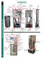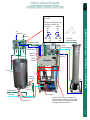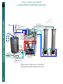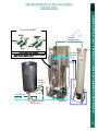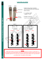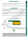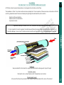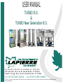
1
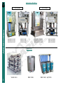
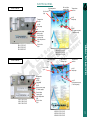
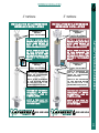
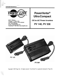
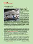
TURBO R.O.
&
TURBO New Generation R.O.
99, RUE DE L’ESCALE, ST-LUDGER, QC. G0M 1W0
WWW.ELAPIERRE.COM
[email protected]
TEL
819.548.5454 - FAX 819.548.5460
CAUTION : This manual includes information and restrictions concerning these products use and restrictions in regards to the manufacturer responsibilities. Manuel
must be read attentively.
14
USER MANUAL
REVERSE OSMOSIS SYSTEM
The system significantly reduces the time and energy required for the sap evaporation process. It also improves the efficiency of
the operation.
The concentration process of the maple sap reduces the volume of green house gases into the atmosphere due to reduced
combustion of wood or fossil fuels, while greatly contributing to the conservation of long term renewable energy sources.
REVERSE OSMOSIS SYSTEM
Concentrating maple sap using a reverse osmosis system
allows the producer to reduce his energy input by 75% or more.
2
ADVANTAGES OF USING AN R.O.
-Reduced energy input
-Time and labour saving
-Allows the expansion of sugar operations
-Maximize efficiency of evaporation equipment
-Helps to protect the environment
TABLE OF CONTENTS
-Available Models
4
-Electrical Panel Details
5
-R.O. Parts Identification
6
-Turbo New Generation R.O. Installation Diagram
7-8
9
-Start-up
10
-Membrane Installation
11
-Membrane Element Conditioning
12
-Operating Instructions: Concentration
13
-Flow Meters Adjustment
14
-Concentration & Performance Test
15
-Operating Instruction: Rinse Cycle
16
-Necessity of Proper Membrane Wash
-Operating Instructions: Soap Washing the Membrane
-Membrane Performance Test
17 - 18
19
20 - 22
-Storage Procedure
23
-Operating Instructions: Washing the Membrane for Storage
24
-Factors Affecting R.O. Membrane Performance
25
-Effect of Pressure, Temperature, Salt Concentration, Recovery & PH
26 - 30
-Troubleshooting
31 - 32
-Sources of Information
33
-Sources of Information
33
-Appendix
34
35
36
37
1 Performance Test Log Table
2 Correction Factors
3 Membrane Performance Table
4 Specifications all Models
TABLE OF CONTENTS
-Turbo R.O. Installation Diagram
3
AVAILABLE MODELS
AVAILABLE MODELS
2000 series
NG-8041-125-3HP
NG-8042-250-3HP
NG-8140-600-5HP
8041-125-3HP
8042-250-3HP
8140-600-5HP
NG-8240-1200-10HP
NG-8340-1800-15HP
NG-8440-2400-20HP
8240-1200-10HP
8340-1800-15HP
8440-2400-20HP
OPTIONAL
Vessel racks
4
3000 series
Wash tanks
Wash tank / sap filters
ELECTRICAL PANEL
2000 series
High temperatur
light
Out of order
light
Recirculation
running light
Temperature
monitor
on/off
Feed pump
Temperature
monitor
on/off
Feed pump
on/off
High pressure pump
(1 switch/pump)
on/off
High pressure pump
(1 switch/pump)
Recirculation
running light
8041-125-3HP
8042-250-3HP
8140-600-5HP
Out of order
light
NG-8041-125-3HP
NG-8042-250-3HP
NG-8140-600-5HP
High temperature
light
3000 series
Recirculation
running light
Out of order
light
Temperature
monitor
on/off
Feed pump
ELECTRICAL PANEL
High temperature
light
Temperature
monitor
on/off
High pressure pump
(1 switch/pump)
on/off
Feed pump
on/off
High pressure pump
(1 switch/pump)
Recirculation
running light
High temperature
light
8240-1200-10HP
8340-1800-15HP
8440-2400-20HP
Out of order
light
NG-8240-1200-10HP
NG-8340-1800-15HP
NG-8440-2400-20HP
5
PARTS IDENTIFICATION
Permeate
flow meter
High pressure
gauge
Instructions
label
Concentration
Low pressure
adjustment valve (#2)
gauge
Wash/concentration
valve(#3)
DOUBLE HORIZONTAL
MECANIQUE
RELACHEURPARTS
IDENTIFICATION
Concentrate
flow meter
Concentrate
sampling valve
wash tank
High pressure
vessel
Electrical
control panel
model & serial #
inside panel
Sap
inlet
Permeate
outlet
Outlet to high
pressure vessel
Heat element
Thermostat
(optional)
Pressure shut-off
valve (#4)
Concentrate
flow meter
Concentrate
sampling valve
Instructions
label
High pressure
gauge
Permeate
Outlet
Concentrate
return
inlet
Pressure
control
valve(#1)
High Pressure
feed manifold
Feed pump
High pressure
pumps
Recirculation
Pump
Low pressure
gauge
Permeate
flow meter
Wash/concentration
valve(#3)
High pressure
outlet manifold
Concentration
adjustment valve (#2)
Pressure control
valve(#1)
Permeate valve(#6)
Electrical
control panel
model & serial #
inside panel
feed pump
64
High pressure
outlet manifold
Concentrate valve(#5)
Pressure shut-off
valve (#4)
High Pressure
feed manifold
High pressure
pumps
Follow arrows on handles to determine
flow direction
ex:
If the top valve is on Wash/drain, liquid
is going down to the bottom valve
Concentrate
Permeate
tank
tank
Out to
concentrate tank
Inlet
Out to
permeate tank
Inlet
drain wash
tank
drain wash
tank
In from permeate flow meter
(back of R.O.)
From high
pressure pump manifold
In from concentrate
flow meter(back of R.O.)
To wash tank
Out to bottom
of permeate flow meter
Concentrate
flow meter
To concentrate
return inlet
Permeate
flow meter
Pre
filter
To drain
Wash tank
feed valve (C)
IN
High pressure
feed manifold
From permeate tank
Lower outlet
out to drain
Feed pump outlet
Feed pump inlet
From sap tank
Permeate feed valve (B)
Sap feed valve (A)
OUT
HORIZONTAL
DOUBLE
MECANIQUE
RELACHEUR
TURBO R.O.
INSTALLATION
DIAGRAM
TURBO R.O. INSTALLATION DIAGRAM
1 PRESSURE VESSEL & EXTERNAL VALVE PANEL
If using an 8’’ sap-filter, a wall or a wash tank mount
(series of pre filters on a frame), hook up the inlet of the
pre filter to the feed pump and the outlet of the pre filter
to the high pressure pump manifold inlet.
5
7
84
Out to
concentrate tank
For draining:
HORIZONTAL
DOUBLE
RELACHEUR
TURBO MECANIQUE
R.O. INSTALLATION
DIAGRAM
TURBO R.O. INSTALLATION DIAGRAM
2 PRESSURE VESSELS & NO EXTERNAL VALVE PANEL
Out to
permeate tank
In from permeate flow meter
(back of R.O.)
Out to bottom
of permeate flow meter
From high
pressure pump manifold
In from concentrate flow meter
(back of R.O.)
Concentrate
To wash tank
flow meter
Permeate
flow meter
To drain
To concentrate
return inlet
Pre
filter
Wash tank
feed valve (C)
From permeate tank
IN
Lower outlet
out to drain
Feed pump outlet
Feed pump inlet
From sap tank
Permeate feed valve (B)
Sap feed valve (A)
For R.O. with built-in pressure vessels (125 et 250 GPM)
simply ignore the hoses going to external pressure vessels
OUT
IN
OUT
Four position valve detail
Out to bottom
of permeate flow meter
From high pressure
pump manifold
To concentrate
return inlet
Wash tank
feed valve (C)
IN
From permeate tank
OUT
Lower outlet
out to drain
From sap tank
Permeate feed valve (B)
Sap feed valve (A)
to Feed pump inlet
HORIZONTAL
MECANIQUE
RELACHEUR
TURBO
NEW GENERATION
R.O.DOUBLE
INSTALLATION
DIAGRAM
TURBO NEW GENERATION R.O. INSTALLATION DIAGRAM
1 PRESSURE VESSEL
5
9
START-UP
- Install the membrane according to the instructions shown on the recirculation vessel.
- Before inserting the membrane in the pressure vessel, make sure that the u-cup on the membrane and all the ‘o'rings on the
adaptors are in perfect condition.
-
Always lightly coat the u-cup and all the ‘o'rings with silicone food grade lubricant (Dow Corning supplied in accessories box)
before their installation.
START-UP
- Once the membrane installation is completed, connect all the high pressure hoses to the reverse osmosis and at the base of the
recirculation pump(s).
- Make sure that all the plumbing is in good condition.
- If the equipment was stored in an unheated room, warm up the room for 2 days before starting the pumps. This precaution will
avoid damage to the pumps if ice has formed inside of the system.
- To start the equipment open the valve on the sap feed line and let the sap fill the unit by gravity.
It is important to thoroughly rinse the membrane before you begin the concentration. You must follow the rinse instructions and
start the equipment.
WARNING
IF the RO has been out of service for the off season, before starting it up, you should take a screwdriver and rotate all
electrical motors one or two revolutions
WARNING
For a multi vessel machine (3 and more), make sure the recirculation cord is disconnected from the RO to avoid running the
pump dry. Start the feed pump, wait until the fluid goes through the flow meter.
Stop the machine , reconnect the electric cord of the recirculation pump to the RO.
When draining the RO, make sure to repeat this operation at the next start up.
There is an optional flow switch available to avoid doing this procedure.
The flow switch is standard on 6 vessel R.O.’s.
10
There is a video explaining concentrate cycle, rinse and soap wash cycle available for
viewing on www.elapierre.com. Click on the video tab from the top menu and then,
New Generation R.O. operating/washing instructions.
4’’ membrane
8’’ membrane
INSTALLATION DE LA MEMBRANE
MEMBRANE INSTALLATION
INSTALLATION DE LA MEMBRANE
MEMBRANE INSTALLATION
U-CUP
VÉRIFIER LES
O’RINGS
VÉRIFIER LES
O’RINGS
CHECK THE O’RINGS
CHECK THE O’RINGS
VOTRE MEMBRANE
POSSÈDE SEULEMENT UN (1)
U-CUP, DONC ENTREZ CE
BOUT DE LA MEMBRANE
VERS LE BAS DU CAISSON.
VOTRE MEMBRANE
POSSÈDE SEULEMENT UN (1)
U-CUP, DONC ENTREZ CE
BOUT DE LA MEMBRANE
VERS LE BAS DU CAISSON.
ONLY 1 U-CUP IS REQUIRED
ON YOUR MEMBRANE. THE
END WITH THE U-CUP MUST
BE DIRECTED TOWARD THE
BOTTOM OF THE PRESSURE
VESSEL.
ONLY 1 U-CUP IS REQUIRED
ON YOUR MEMBRANE. THE
END WITH THE U-CUP MUST
BE DIRECTED TOWARD THE
BOTTOM OF THE PRESSURE
VESSEL.
VÉRIFIER LES
O’RINGS
VÉRIFIER LES
O’RINGS
CHECK THE O’RINGS
U-CUP
CHECK THE O’RINGS
PIÈCES À ASSEMBLER AU
BAS DE LA MEMBRANE
AVANT DE L’INTRODUIRE
DANS LE CAISSON.
PIÈCES À ASSEMBLER AU
BAS DE LA MEMBRANE
AVANT DE L’INTRODUIRE
DANS LE CAISSON.
PARTS TO BE ASSEMBLED
AT THE BOTTOM BEFOM
INTRODUCING THE
MEMBRANE IN THE VESSEL.
PARTS TO BE ASSEMBLED
AT THE BOTTOM BEFOM
INTRODUCING THE
MEMBRANE IN THE VESSEL.
ENDUIRE LES O’RINGS DE
LUBRIFIANT DE GRADE
ALIMENTAIRE LORS DE
L’INSTALLATION.
ENDUIRE LES O’RINGS DE
LUBRIFIANT DE GRADE
ALIMENTAIRE LORS DE
L’INSTALLATION.
APPLY A THIN COAT OF
FOOD GRADE LUBRICANT
ON THE O’RINGS.
APPLY A THIN COAT OF
FOOD GRADE LUBRICANT
ON THE O’RINGS.
819.548.5454
MEMBRANE INSTALLATION
MEMBRANE INSTALLATION
819.548.5454
11
MEMBRANE CONDITIONING
Prior to performing maple sap concentration, it is important to follow these instructions.
The membrane is called hydrophobic in its original state, meaning it will allow water through its pores with difficulty.
The purpose of the conditioning is to make the membrane hydrophilic.
MEMBRANE CONDITIONING
This way the membrane will allow water to pass freely through its pores at a lower pressure.
PROCEDURE
STEP 1
Rinse with water to drain for 15 minutes
Note:
If no permeate is available, you can then use tap water. If using tap water, make sure this water does not contain a large mineral load. It
must also be chlorine free. We also recommend you test the PH. the PH should read between 6 and 7.5
STEP 2
Recirculate 85°F (29.4°C) water in the wash tank for 30 to 45 minutes following the wash cycle instructions.
This step can be performed with or without membrane cleaner, depending if the element is new or used.
STEP 3
Rinse to drain with 500 gallons of water. You can now proceed to concentration.
Note:
At the end of your first concentration day, we recommend performing a mild chemical wash (check manufacturer's PH
recommendations), followed by a thorough rinse with permeate water.
NOTE
12
OPERATING INSTRUCTIONS
CONCENTRATE CYCLE
1. Open sap feed valve (A).
2. Make sure permeate valve (B) and wash tank valve (C) are closed.
3. On the RO front panel set Valve #1 (high pressure control) – open 2 turns.
4. On the RO front panel turn Valve #2 (concentrate needle valve) - open one quarter turn.
6. On the RO front panel make sure the four position concentrate valve is set to Concentrate Reservoir # 1 position. (If using an
external valve panel (turbo model) place the top concentrate valve on Reservoir)
7. On the RO front panel make sure the four position permeate valve is set to Permeate Reservoir # 2 position. (If using an external
valve panel (turbo model) place the top permeate valve on Reservoir).
8. On the RO front panel push the (green) feed button until pressure reaches 25psi on lower pressure gauge then release the feed
button.
9. Once flow starts automatically – push high pressure green start button. You are now concentrating the sap. Double check that sap
concentrate is going into the sap concentrate tank.
10. On the RO front panel set valve #1 pressure between 250 psi and 400 psi. on the high pressure gauge.
11. Adjust concentrate #2 on the R.O. front panel, to concentrate at approximately 8 Brix (remove 2 thirds of the water from total
liquid) permeate gauge set to 6 gpm, concentrate gauge set to 3 gpm (refer to the next page: flow meters adjustment).
12. Wait 3 to 5 minutes, and then adjust valve #2 on the R.O. front panel, to get desired concentration. Try and balance the concentrate
with what the evaporator is using, i.e. maintain a constant level in the concentrate tank or just slightly increase the level of
concentrate in the tank particularly on a long boil.
OPERATING INSTRUCTIONS
5. On the RO front panel make sure Valve #3 is on concentrate closed cycle.
13. After RO has run for 10 minutes, switch only the permeate 4 position valve to wash position (If using an external valve panel
(turbo model) place the bottom permeate valve on wash and then, the top permeate valve to wash/drain) and fill stainless steel
wash tank ¾ parts full with clean permeate for rinsing the membrane. Return permeate valve to reservoir position. Turn on
heating element in the wash tank to heat the rinsing water.
14. If the RO runs out of sap and shuts down or has reached the maximum concentration time of 6 – 7 hours, then shut down and rinse
the membrane as explained in the rinse cycle operating instructions
13
FLOW METERS ADJUSTMENT
Permeate
flow meter
Concentrate
flow meter
GPM:Gallons/Minute
LPM:Liters/Minute
FLOW METERS ADJUSTMENT
Read on top
of the Lead float
To determine the percentage of concentration,
divide the permeate flow by the total of the permeate
and the concentrate..
Ex. : concentrate= 2.5 GPM
permeate= 7.5 GPM
Percentage of concentration:
7.5 / (2.5 + 7.5)= 75 % concentration
Lead
float
Example 1:
Example 2:
Sap:
2 brix
Concentrate: 4 brix
50% water removal
from total liquid
CONCENTRATE
GPM
LPM
PERMEATE
GPM
20
CONCENTRATE
LPM
GPM
20
LPM
PERMEATE
GPM
20
LPM
20
18
70
18
70
18
70
18
70
16
60
16
60
16
60
16
60
14
14
50
12
10GPM
Sap:
2.5 brix
Concentrate: 7.5 brix
75% water removal
from total liquid
10
8
40
30
10
8
12
40
10GPM
10
8
30
6
20
4
2
40
30
10
8
2.5GPM
2
40
30
7.5GPM
6
20
4
10
50
12
6
20
4
10
14
50
12
6
2
14
50
20
4
10
2
10
WARNING
To make sure the permeate is free of sugar, an easy test is to evaporate 1 gal (4 L) down to 1.5 oz (40ml) after 1 or 2
hours of operation, let it cool down and taste it. The concentration should be high enough to taste sweet. If there is sugar in
the permeate, repeat this test 1 or 2 hours later. If it still tastes sweet, check the condition of the ‘o’rings at both ends of
your membrane (refer to the membrane installation diagram)
14
CONCENTRATION & PERFORMANCE TEST
You should always fill in a log table(see appendix 1). The purpose of the log table is to keep a data of all parameters during the
operation and performance test of your equipment. (see performance test section for more details)
To evaluate the good working order of the reverse osmosis equipment it is important to know the parameters detailed in performance
tests.
The use of reverse osmosis in the maple industry has a direct impact on operation costs. The cost of combustible fuels and labour keep
increasing and will probably remain high into the future. For all these reasons, many producers are looking to reduce their expenses to
keep a reasonable profitability of their operation.
R.O. system is more and more targeted to increase the concentration level above 8 brix. It is possible to do so. However, it will be
necessary to plan an additional installation of extra membrane elements. This installation can be justified by the saving of energy and
labour required for sap processing.
The following cost comparison chart and graphic demonstrate the energy-saving generated by the concentration increase of maple
sap.
Optional outlets:
If you plan to expand in the future, optional factory installed outllets are available
for future extra vessels plug-in capabilities.
Ex: At 4 Brix it takes 2g of oil to make 1 gal of syrup
At 8 Brix it takes 1g of oil to make 1 gal of syrup
On an average efficiency oil fired evaporator
CONCENTRATION & PERFORMANCE TEST
INCREASE OF CONCENTRATION
NOTE
15
OPERATING INSTRUCTIONS
RINSE CYCLE
1. Close sap feed valve (A). Open permeate feed valve (B).
OPERATING INSTRUCTIONS
2. On the RO front panel open Valve #3 (concentrate valve) to the wash position. Leave the 4 way concentrate valve to the
concentrate tank. (If using an external valve panel (turbo model) place the top concentrate valve on Reservoir)
Start the green feed pump only and run for 5 minutes. This pushes all the sugar centrate from the membrane to the concentrate
tank.Shut off the feed pump and switch the concentrate 4 way valve to drainIf using an external valve panel (turbo model) place the
bottom concentrate valve to drain and then, the top concentrate valve on wash/drain) Run this rinse for 15 minutes and then shut
the RO off.
3. Close the permeate feed valve (B) and open the wash tank feed valve (C). Set the 4 way concentrate valve to wash position, set the
4 way permeate valve to wash position. (If using an external valve panel (turbo model) place the bottom permeate valve to wash
and then, the top concentrate valve on wash/drain).
4. Turn off heating unit on the wash tank.
5. Start the green feed pump and let run until it shuts off automatically (43 degrees C.) You do not need to stay at the camp for this
operation.
6. When you return to the camp in the morning drain the wash tank.
7. Close the wash tank feed valve (C) and open permeate feed valve (B).
8. Start the green feed pump only and rinse the membrane for 15 minutes minimum. If the RO is not going to be used for two or three
days rinse the membrane daily for five to ten minutes with valves in the same position.
9. Your membrane is ready to return to concentration cycle (1-10 above) .
10. When your membrane output slows down by 10% you need to do a soap wash. Please follow the soap washing instructions
carefully.
There is a video explaining concentrate cycle, rinse and soap wash cycle available for
viewing on www.elapierre.com. Click on the video tab from the top menu and then,
New Generation R.O. operating/washing instructions.
NOTE
16
CLEANING
THE NECESSITY OF A PROPER MEMBRANE WASH
All filtration systems require cleaning at more or less regular interval to allow constant flow.
The membrane is a filter. It can retain invisible molecules and particles. The accumulation of these molecules on the surface of the film
result in a gradual decrease of the volume of water passing through the membrane film, which results in:
Reduction of the permeate flux.
Reduction of the concentrate brix.
A pressure increase.
A permeate flow drop of around 10% to 15% should be corrected promptly by a soap wash.
It is also important to monitor regularly the membrane performance because a major performance drop may result in
irreversible damage. In some cases it may be necessary to wash more than once to bring the membrane performance back.
CLEANING
-
Membrane
Semi permeable film that retains the organic and minerals while allowing water to pass through.
Feed mesh (vexar)
Mesh which acts as a feed channel and for the membrane recirculation.
Permeate mesh (vexar)
A fine mesh that allows the permeate to flow towards the perforated tube at the center of the element.
17
CLEANING
THE NECESSITY OF A PROPER MEMBRANE WASH
WARNING
When washing, you must follow the manufacturer's recommendations.
There are different types of membranes available on the market. The cleaning product concentrations may vary from one
manufacturer to the other. The cleaning solution's PH (water & detergent) must be adjusted according to the membrane
specifications.
We recommend using a PH meter or a PH test paper strip to determine the required detergent quantity to prepare the cleaning solution.
Cleaning is always followed by a rinse with sufficient quantity of permeate. For best results, we recommend using a 25°C (77°F)
permeate. The minimum quantity required for an 8 inch membrane is 500 gallons. Increase rinse time by five minutes (100 gal.) for
every additional membrane mounted in series.
CLEANING
In order to get the maximum lifetime of your membranes you should:
-Follow the manufacturer's recommendations.
-Follow up on the equipment performance.
-Do the proper cleaning and rinsing when necessary.
-Never improvise home remedies such as chlorine or other non-recommended products.
-Never leave the membrane in a concentrated sap solution when the equipment isn't running.
-Always perform a short rinse immediately after concentration cycle stops.
NOTE
18
OPERATING INSTRUCTIONS
SOAP WASHING THE MEMBRANE
1. After you have determined that you need to do a soap wash and have completed steps 1 to 4 from the rinse cycle. (refer to
OPERATING INSTRUCTIONS, CONCENTRATE CYCLE ).
2. Start the green feed pump and note the temperature of permeate rinse, it should be at least 28 degrees C.
3. Add soap to the wash tank slowly measuring the quantity used, test with litmus paper to measure ph of the soap solution. Continue
adding soap and measure the PH until you reach a PH level of 11 for a Mark 1 membrane. Once you have reached the desired PH
level record how much soap was used to achieve the desired PH level. This will allow you to simply add this amount of soap to the
wash tank the next time. It is important to always have the same amount of permeate in the wash tank every time.
5. Drain the wash tank and the RO, allow it to cool for 15 minutes as adding cool rinsing permeate could cause the flow meters to
break.
6. Close the wash tank feed valve (C) and open permeate feed valve (B).
7. Set the 4 way concentrate valve to drain position, set the 4 way permeate valve to drain position (If using an external valve panel
(turbo model) place both bottom valves to drain).
8. Start the green feed pump only and rinse the membrane for 20 minutes minimum.
9. Remove the filter cartridge from the big blue housing at the front of the RO and replace it with a new filter cartridge. Tag the
removed cartridge to be used for soap washing only. Once a filter cartridge has been used for soap washing, it may never be used
again for sap.
10. If you have lots of permeate, a longer rinse cycle to remove the soap is desirable. Soap left in the membrane can cause an off-flavor
in your syrup.
OPERATING INSTRUCTIONS
4. Circulate the washing solution for 15 minutes. Turn off the feed pump for 15 minutes. Repeat this process 2 more times.
NOTE
19
MEMBRANE PERFORMANCE TEST
After purchasing a new R.O., or a new membrane, on the second day of use, check the performance of the membrane(s) after a warm
wash and cold permeate rinse.
The permeate flow meter reading will be your reference 100%.
To check the performance of a membrane, you must concentrate permeate. We recommend that you set the pressure at 225 PSI and
adjust the concentrate flow at 3 GPM.
MEMBRANE PERFORMANCE TEST
Once the permeate data reading is taken from the flowmeter, you divide the data flow by the temperature correction factor. The
permeate flow is influenced by the temperature. The higher the sap temperature, the higher the permeate flow will be and vise-versa.
(see appendix 2 for correction factors table)
A permeate flow drop of around 10% to 15% should be corrected promptly by a soap wash.
It is also important to monitor regularly the membrane performance because a major performance drop may result in
irreversible damage. In some cases it may be necessary to wash more than once to bring the membrane performance back.
To figure out the 100% capacity of the membrane at 13°C (55.4°F).
5.2 GPM / 0.866 (correction factor 8°C (46.4°F) = 6.00 GPM.
This result must be written down to compare the performance of the membrane for a minimum of once/month. Therefore, if we wish to
revise the performance of the membrane at a given moment, we must redo the above exercise and compare the result to the original test
of the membrane.
Ex. : If we get 5.5 GPM at the second test (corrected at 13°C (55.4°F)) the performance of the membrane would be:
((6.00 - 5.5) / 6.00) x 100 = 8.3% performance loss
OR
5.5 / 6.0 = 91.7% efficiency
(see appendix 3 for membrane performance table)
NOTE
20
PERFORMANCE TEST
(REFER TO LOG TABLE IN APPENDIX 1)
1. Brix percentage of the raw sap.
It is the sap before the concentration process. Take note that the liquid temperature influences the reading on the hydrometer or
refractometer.
Always check the temperature range of the brix measurement device.
2. Brix percentage of the concentrate.
This test is normally performed after 15 to 30 minutes of operation.
For the measurement, follow the recommendations for the raw sap.
4. Concentrate flow
Follow the permeate flow procedure.
5. Total flow
To evaluate the total flow. Add the data of the column #3 (permeate) and column #4 (concentrate). The result will be the total flow
per minute. Multiplied by 60 minutes you get the total flow per hour.
Ex. : 2+8X60= 600 GPH
Take note, this data is influenced by temperature variation. The degree of concentration, the condition of the sap, the condition of
the membranes and the operation pressure (PSI).
6. Concentration percentage
The purpose of knowing the percentage of concentration, is to make sure not to exceed the operation recommendation.
PERFORMANCE TEST
3. Permeate flow
Note the reading of the permeate flow meter in litres or gallons per minute. To find out the flow per hour, multiply the data per 60
minutes.
Ex. : 3 GPM x 60 minutes = 180 GPH
Ex. : For a R.O. equipped with a 600 GPH pump and a membrane of 600 GPH the degree of concentration should not exceed 70%.
By increasing the filtration surface by the addition of extra membranes, it is possible to surpass this recommendation to obtain a
concentrate with a higher level of sugar and minerals.
The osmotic pressure increases with the degree of concentration and has a down effect on the membrane flow.
There is a video explaining concentrate cycle, rinse and soap wash cycle available for
viewing on www.elapierre.com. Click on the video tab from the top menu and then,
New Generation R.O. operating/washing instructions.
NOTE
21
PERFORMANCE TEST
7. Operation Temperature
The operation temperature, is the temperature of the sap at the inlet of the equipment. The temperature of the sap has a direct
effect on the permeability of the membrane. The colder the sap is, the lower the flow through the membrane film will be. To make
the evaluation of the treatment capacity of the membrane, we must refer to the temperature correction factor. (appendix 2)
PERFORMANCE TEST
8. Pressure of Operation
The pressure of operation is another important element when conducting a performance test. The pressure has a direct effect on
the flow and the permeability of the membrane. To raise the level of concentration requires an increase of the pressure to maintain
the flow. For the long life of the membranes, it is preferable to operate at a lower pressure than the recommended limit. Always
perform the performance test at the same pressure. It is important to maintain a good reference.
22
9. Corrected Permeate Flow
Divide the reading of the permeate flow meter by the appropriate temperature correction factor. (appendix 2)
NOTE
STORAGE PROCEDURE
At the end of the maple season, it is time to prepare your equipment for storage.
To begin, you must make sure that you have a good volume of permeate to allow a proper wash and rinse of your membranes.
1. Even if you send your membrane(s) to be washed by the equipment manufacturer, it is important to wash and rinse the
membranes before pulling them out of the recirculation vessel.
2. Disconnect the pressure hoses from the pressure vessels and the electric cord from the R.O.
4. Insert the membrane(s) in the canister(s). If you send the units to the factory, add 1 litre of permeate to the canisters. The
membranes must be kept in a damp environment. Long storage solution : for each 8” x 40” membrane: mix ½ cup of SMBS
(sodium metabisulfite) with 4 gallons (18 litres) of cold permeate and 1 gallon (3.75 litres) of glycerine(to avoid freezing).
Mix well and add the solution to the membrane in the storage canister. For 4” x 40” membrane mix 1/8 of a cup of SMBS to
1 gallon (4.5 litres) of cold permeate and add 1 litre of glycerine, mix well.
5. Drain the unit and all pumps completely.
6. It is strongly recommended to store the R.O. in a dry and heated room.
This precaution will avoid certain problems due to humidity and bad surprises caused by an incomplete drainage.
There is a video explaining concentrate cycle, rinse and soap wash cycle available for
viewing on www.elapierre.com. Click on the video tab from the top menu and then,
New Generation R.O. operating/washing instructions.
STORAGE PROCEDURE
3. Unfasten the bolts from the top lid(s) and pull the membrane(s).
NOTE
23
WASHING THE MEMBRANE FOR STORAGE
1. When washing your membrane for end of year storage, the procedure is very similar to membrane washing. Repeat steps1-2-3
from the: SOAP WASHING THE MEMBRANE section.
WASHING THE MEMBRANE FOR STORAGE
2. During this process you must use a long washing Cycle. Circulate the washing solution for 30 minutes. Turn off the feed pump for
30 minutes. Repeat this process 2 more times using a circulation of 30 minutes and a rest period of 3 hours.
3. Drain the wash tank and the RO, allow it to cool for 15 minutes as adding cool rinsing permeate could cause the flow meters to
break.
4. Close the wash tank feed valve (C) and open permeate feed valve (B).
5. Set the 4 way concentrate valve to drain position, set the 4 way permeate valve to drain position (If using an external valve panel
(turbo model) place both bottom valves to drain).
6. Start the green feed pump only and rinse the membrane with at least 500 gallons of permeate.
7. Remove the prefilter and dispose of it.
8. Remove the membrane from the stainless steel vessel, remove the plug and cone from the bottom of it and put the membrane in the
storage vessel. Mix ½ cup of SMBS and one litre of clean permeate in a clean pail, stir well and pour over the membrane in the
storage vessel. Install the cap on the storage vessel and store in a heated area until it is required for service next season.
9. Replace the cap on the stainless steel vessel and store the plug and cone in a safe place such as a storage cabinet.
10. Remove the high pressure hose from the stainless steel membrane vessel and make sure the drain valve at the bottom of the
stainless steel membrane vessel is in the drain position.
11. Make sure the 4 position valves are both drained well. Also make sure the flow gauges have drained.
12. Open the drain valve in the rear of the RO and remove the drain plug from the feed pump and drain well. Tip the machine forward to
help drain the unit.
13. Plug any of the hoses going into the RO to prevent varmints from nesting there over the winter.
14. Next season before starting the machine, take a screwdriver, place it in the slot in the end of the electric motor. Repeat this process
on all three motors, the feed pump, the high pressure pump and the circulating pump.
15. Lubricate the membrane ‘U’ cup and ‘O’ rings before installing into the stainless steel vessel.
24
FACTORS AFFECTING R.O. MEMBRANE PERFORMANCE
What will follow defines the key terms and offers a quick overview of the factors affecting the performance of the reverse osmosis
membrane elements.
Including the effect of pressure, temperature, concentration of organics, sugars, mineral salts contained in the maple sap, and recovery
of permeate and the effect of the PH.
NOTE
FACTORS AFFECTING R.O. MEMBRANE PERFORMANCE
The technology of reverse osmosis can be complicated. Especially in absence of knowledge for the terminology that describes the
aspects of the operation in relation with different variables.
25
EFFECT OF PRESSURE
Feedwater pressure affects both the water flux and salt rejection of RO membranes. Osmosis is the flow of water across a membrane
from the dilute side toward the concentrated solution side. Reverse osmosis technology involves application of pressure to the
feedwater stream to overcome the natural osmotic pressure. Pressure in excess of the osmotic pressure is applied to the concentrated
solution and the flow of water is reversed.
EFFECT OF PRESSURE
A portion of the feedwater (concentrated solution) is forced through the membrane to emerge as purified product water of the dilute
solution side.
Osmosis
The water crosses a semi permeable membrane towards the higher concentration area of the liquid to balance the two solutions. Once
the level of the liquid is equivalent, the height difference between the concentrated and the diluted part correspond to the osmotic
pressure.
Reverse osmosis
By applying a pressure exceeding the osmotic pressure, the water flow direction will be reversed which is called reverse osmosis.
NOTE
26
EFFECT OF TEMPERATURE
As Figure 3 demonstrates, membrane productivity is very sensitive to changes in feedwater temperature. As water temperature
increases, water flux increases almost linearly, due primarily to the higher diffusion rate of water through the membrane.Increased
feedwater temperature also results in lower salt rejection or higher salt passage. This is due to a higher diffusion rate for salt through
the membrane. The ability of a membrane to tolerate elevated temperatures increases operating latitude and is also important during
cleaning operations because it permits use of stronger, faster cleaning processes.
NOTE
EFFECT OF TEMPERATURE
As shown in Figure 2, water flux across the membrane increases in direct relationship to increases in feedwater pressure. Increased
feedwater pressure also results in increased salt rejection but, as Figure 2 demonstrates, the relationship is less direct than for water
flux. Because RO membranes are imperfect barriers to dissolved salts in feedwater, there is always some salt passage through the
membrane. As feedwater pressure is increased, this salt passage is increasingly overcome as water is pushed through the membrane at
a faster rate than salt can be transported.
27
EFFECT OF RECOVERY
As shown in Figure 1, reverse osmosis occurs when the natural osmotic flow between a dilute solution and a concentrated solution is
reversed through application of feedwater pressure. If percentage recovery is increased (and feedwater pressure remains constant),
the salts in the residual feed become more concentrated and the natural osmotic pressure will increase until it is as high as the applied
feed pressure. This can negate the driving effect of feed pressure, slowing or halting the reverse osmosis process and causing permeate
flux and salt rejection to decrease and even stop (please see Figure 6).
The maximum percent recovery possible in any RO system usually depends not on a limiting osmotic pressure, but on the
concentration of salts present in the feedwater and their tendency to precipitate on the membrane surface as mineral scale.
EFFECT OF RECOVERY
The most common sparingly soluble salts are calcium carbonate (limestone), calcium sulphate (gypsum), and silica. Chemical
treatment of feedwater can be used to inhibit mineral scaling.
NOTE
28
EFFECT OF SALT CONCENTRATION
Figure 5 demonstrates that, if feed pressure remains constant, higher salt concentration results in lower membrane water flux. The
increasing osmotic pressure offsets the feedwater driving pressure. Also illustrated in Figure 5 is the increase in salt passage through
the membrane (decrease in rejection) as the water flux declines.
NOTE
EFFECT OF SALT CONCENTRATION
Osmotic pressure is a function of the type and concentration of salts or organics contained in feedwater. As salt concentration
increases, so does osmotic pressure. The amount of feedwater driving pressure necessary to reverse the natural direction of osmotic
flow is, therefore, largely determined by the level of salts in the feedwater.
29
EFFECT OF PH
The PH tolerance of various types of RO membranes can vary widely. Thin-film composite membranes such as FILMTEC FT30
membrane are typically stable over a broader PH range than cellulose acetate (CA) membranes and, therefore, offer greater operating
latitude (see Figure 4). Membrane salt rejection performance depends on PH. Water flux may also be affected.
EFFECT OF PH
Figure 7 shows that water flux and salt rejection for FILMTEC FT30 membranes are essentially stable over a broad PH range. As
illustrated in Figure 4, the stability of FT30 membrane over a broad PH range permits stronger, faster, and more effective cleaning
procedures to be used compared to CA membranes.
30
NOTE
TROUBLESHOOTING
PROBLEMS & SOLUTIONS
Problem The feed pump starts, but it stops as soon as I release the feed switch.
Solution 1
2
3
4
5
Check if the feed pressure reaches at least 20 psi.
Check the feed valve, it must be open.
Check the prefilters, they may have to be replaced.
Check if the plumbing is not plugged or damaged. A bad joint or bad seal will allow air in the system causing this
problem.
Check the feed pump.
Solution 1
2
3
4
Check if the feed pressure reaches at least 20 PSI.
Replace the pre-filter cartridges.
Check for obstruction of the feed line or the feed pump.
Check the feed pump.
Problem The performance of the R.O. equipment drops once it is started.
Solution 1
Make sure the recirculation pump is running. Just place your hand under the recirculation pump motor if you feel
air circulating the motor is running. If the recirculation system does not operate the membrane will foul rapidly.
2
At the beginning and the end of the sugar season, it is important to do a tight follow up of the membranes condition.
During these periods, it is necessary to wash the membranes more often to keep a good level of performance.
In the first days of the operation due to the cytoplasmic cells activity inside the maple, the sap has a tendency to foul
the membranes. These cells produce an antifreeze like substance, which protects the maple during the winter frost.
Frequent washing will be necessary during that period to avoid fouling.
TROUBLESHOOTING
Problem The feed pump starts, but the R.O. stops as soon as I press on the high pressure switch.
NOTE
31
TROUBLESHOOTING
PROBLEMS & SOLUTIONS
Problem The recirculation pump does not operate
Solution Normally when the recirculation fails, it will cause a complete stop of the R.O. the out of order light will come on.
1 Control panel.
A Check if the breaker is on the set position.(reset if necessary)
(Note: on older models the equipment will keep on running if the recirculation breaker is out. But on the newer
models if a breaker is out it will be impossible to restart the equipment.
TROUBLESHOOTING
B Check if the recirculation overload is on, if it is out, the R.O. stops and the out of order light comes on.
C Check the electric wiring to the plug and the connections in the motor.
(The R.O. will keep on running despite the recirculation is out.)
2 Recirculation motor.
A Check if the recirculation motor can turn freely, using a flat screw driver at the base of the motor.
B If the motor turns freely check the electric wiring to the motor.
If the wire connections and the power are fed properly through the electric circuit, the motor will have to be
repaired or replaced by a qualified technician.
Problem There is a squealing noise coming from one of the electric motors.
Solution It is not generally a very serious problem. Most likely it is a bearing failure, due to excessive wear or rust caused b
dampness. It must be repaired immediately before extensive damage occurs. A qualified technician can replace the
bearings and check the pump to make sure it is in good running order.
NOTE
32
SOURCES OF INFORMATION
-Filmtech (Dow Chemicals)
-Complete filtration resource (CFR)
Steve Bedard
Carl Lapierre
Donald Lapierre
Steve O’Farrell
Don Dodds
Jeff Goulet
Anick Lapierre
Keith Brown
Matt Williams
Tom Patterson
TERMINOLOGY & DEFINITIONS
Recovery (permeate)
The percentage of the water removed from the raw sap through the membrane.
That percentage can be increased by adjusting the concentrate valve.
Rejection (concentrate)
Concentration percentage of solid residue removed from water by the membrane.
Passage
Opposite of the rejection. Concentration percentage of solids dissolved into the liquid going through the membrane.
Permeate
Purified water produced by the membrane.
SOURCES OF INFORMATION
CONTRIBUTORS
Total flow rate
The flow of the liquid going through the membrane. Normally measured in litres per minute (LPM) or gallons per minute (GPM).
Concentrate flow
The concentrate flow coming out from the membrane. This concentrate contains all the organic and mineral residues of the liquid.
Measured in litres per minute (LPM) or gallons per minute (GPM).
Permeate flow
The flow of permeate produced by the surface of the membrane. Measured in liters per minute (LPM) or gallons per minute
(GPM).
33
APPENDIX 1
PERFORMANCE TEST LOG TABLE
Date
1
2
% Brix of the
maple sap
% Brix of the
concentrate
4
3
5
6
7
8
9
Hour
Permeate
flow (GPM)
Concentrate
flow (GPM)
total flow (3
+ 4) x 60
%
Concentration
Operation
temperature
pressure of
operation
13 C
375 PSI
corrected
permeate
flow
Test
3 / (3+4)
PERFORMANCE TEST LOG TABLE
2%
34
8 brix
7.5
2.5
600 GPM
75%
concentration
Temp ° C
Temp ° F
Correction
factor
Temp ° C
Temp ° F
Correction
factor
0
32.0
0.672
13
55.4
1.000
1
33.8
0.695
14
57.2
1.028
2
35.6
0.719
15
59.0
1.055
3
37.4
0.742
16
60.8
1.084
4
39.2
0.766
17
62.6
1.112
5
41.0
0.790
18
64.4
1.142
6
42.8
0.816
19
66.2
1.170
7
44.6
0.842
20
68.0
1.200
8
46.4
0.866
21
69.8
1.229
9
48.2
0.893
22
71.6
1.259
10
50.0
0.919
23
73.4
1.289
11
51.8
0.946
24
75.2
1.319
12
53.6
0.973
25
77.0
1.350
CORRECTION FACTORS
APPENDIX 2
CORRECTION FACTORS
NOTE
35
MEMBRANE PERFORMANCE TABLE
APPENDIX 3
MEMBRANE PERFORMANCE TABLE
36
# membrane
28736465
Data reading
Temp ° C
Temp ° F
Corrected data
to 13°C / 55.4
2000
Date
5.2
8
46.4
6.00 (100%)
Date
2001
5.1
10
50.0
5.50 (91.7%)
2002
2003
2004
2005
For a multi membranes machine, test all the membranes together
NOTE
Frame
Junior
frame
Junior
frame
2000
2000
-2000
-3000
-2000
-3000
-3000
-3000
R.O. model
100 g/h
Junior R.O.
200 g/h
Junior R.O.
125 g/h
-Turbo
-New gen.
250 g/h
-Turbo
-New gen.
600 g/h
-Turbo
-New gen.
1200 g/h
-Turbo
-New gen.
1800 g/h
-Turbo
-New gen.
2400 g/h
-Turbo
-New gen.
1 1/4’’
1 1/4’’
1 1/4’’
1 1/4’’
1 1/4’’
1 1/4’’
1’’
1’’
Feed inlet
size
4x
5microns
3x
5microns
2x
5microns
1x
5microns
1x
5microns
1x
5microns
1x
5microns
1x
5microns
Prefilter
(1 phase)
220 v.
(1 phase)
220 v.
(1 phase)
220 v.
(1 phase)
220 v.
(1 phase)
220 v.
(1 phase)
220 v.
(1 phase)
220 v.
(1 phase)
220 v.
Volts
(1 phase)
115
@ 220 v.
(1 phase)
90
@ 220 v.
(1 phase)
65
@ 220 v.
(1 phase)
40
@ 220 v.
25
21
11.5
11.5
Total
nominal
Amps
(4x20 amps)
4 x5 HP
(3x20 amps)
3 x5 HP
(2x20 amps)
2 x5 HP
(20 amps)
5 HP
(13 amps)
3 HP
(13 amps)
3 HP
(7 amps)
1.5 HP
(7 amps)
1.5 HP
H.P. pump
3/4 HP (6 amps)
/pressure
vessel(4)
3/4 HP (6 amps)
/pressure
vessel (3)
3/4 HP (6 amps)
/pressure
vessel (2)
3/4 HP (6 amps)
/pressure
vessel (1)
1/2 HP (4 amps)
/pressure
vessel (2)
1/2 HP (4 amps)
/pressure
vessel (1)
Built-in HP
pump
Built-in HP
pump
pump
Recirculation
SPECIFICATIONS (STANDARD MODELS)
4x (8’’x40’’)
3x (8’’x40’’)
2x (8’’x40’’)
1x (8’’x40’’)
2x (4’’x40’’)
1x (4’’x40’’)
2x (4’’x40’’)
1x (4’’x40’’)
Membrane
(12.5 amps)
or 3HP
(11 amps)
2 HP
(11 amps)
2 HP
(7 amps)
1 HP
(7 amps)
1 HP
(4 amps)
1/2 HP
(4 amps)
1/2 HP
(4 amps)
1/2 HP
(4 amps)
1/2 HP
Feed pump
APPENDIX 4
SPECIFICATIONS (STANDARD MODELS)
37
NOTE
NOTE
38
NOTE
NOTE
39
99, RUE DE L’ESCALE, ST-LUDGER, QC. G0M 1W0
WWW.ELAPIERRE.COM
[email protected]
TEL
819.548.5454 - FAX 819.548.5460
REVISED : MARCH 3, 2010 VERSION: 01