1
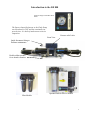
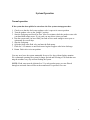
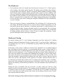
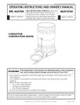
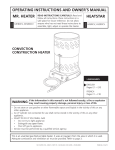
LAND BASED 800
INSTALLATION MANUAL
&
OWNER’S MANUAL
Spectra Watermakers, Inc.
20 Mariposa Road, San Rafael, CA 94901
Phone 415-526-2780 Fax 415-526-2787
E-mail: [email protected]
www.spectrawatermakers.com
April-18-06
1
2
Introduction to the LB 800
Pressure Gauge and Product Flow
Meter
The Spectra Intensifier known as the Clark Pump
was introduced in 1997 and has continually improved since. It is built of modern non corrosive
composites.
Pressure relief valve
Front View
Quick disconnect fitting to
facilitate maintenance.
Double rubber mounts
for to absorb vibration
Optional Flush & Service module
Filter Module
3
Getting Started
Unpack the system and inspect it to make sure that it has not been damaged in shipment.
Refer to the shipping list for your system to make sure you have received all of the components listed. Do not discard any packaging until you have found and identified all of the
parts. The small installation parts are listed on the kit list.
Warning! We will not be held responsible for shortages and or freight damage that are not
reported within thirty days of the ship date.
Study the system layout diagram, component photos and descriptions before beginning your
installation. This will assist you in understanding the function of each component.
Layout the system. Before starting the installation identify the location where each module
and component will be placed. Insure that there is proper clearance around the components
for removal of filters and system service. Also check to make sure you have adequate tubing
and hose before starting so additional parts may be ordered.
Shipping List
?
?
?
?
?
?
?
?
?
?
?
?
?
?
(2) High Pressure Clark Pump and a 40” Reverse Osmosis Membrane Modules.
Accumulator Tank
Monitor Gauge panel
Installation Fittings Kit
Hand held Salinity monitor
5/8”(14.75mm) Hose 25 Feet
(2) 3/4” (19.05mm) Hose 10 Feet
1/4 product tubing (50’)
Feed Water flow meter
DF-1 prefilter assembly
Product sampling 3-way valve
(2) Brine Service Hose
Optional Flush/Service Module
Product Water Manifold
4
Plastic fittings should have 3-4
wraps of Teflon tape and will
thread almost all the way in.
Leave the first pipe thread uncoated. Avoid getting dirt or debris in the system during assembly. Avoid tight bends and elbows. Secure piping away from
moving objects and protect from
chafe.
Plumbing Layout
Brine Discharge to Adjacent
well or drain
Accumulator, Factory precharged. Install in any position
and plumb as shown.
Fresh water flush inlet to
charcoal filter.
Plumb to fresh water
system.
20 & 5 micron filters.
Do not mount over
electrical equipment.
Leave clearance below
for filter change.
Optional Service/flush Module
Wire pump power terminal strip to
specifed power source.
12 Volt DC pump uses 10 Amps
24 Volt DC pump uses 5 Amps
AC Pumps use 1 amp
Pressure Gauge
Feed Water Inlet from
Customer supplied
pump. 3GPM, 100PSI
Feed Flow Meter
5
Product Water and Pressure Gauge Tube Installation
Sampling Tap for testing the product
water or for service procedures.
Put enough tube on this port to reach
your service (pickling) container.
Product to tank.
Route the product water from the
valve into the top of the tank. Install
a tee in the water fill or tap a pipe
thread into an inspection port.
DO NOT! feed into a vent line,
manifold or the bottom of the tank.
Make sure that there is no restriction
in this piping.
Product sampling valve . Mount using the supplied plastic straps as shown.
Note: the handle is pointing in the direction of the
flow.
Pressure Gauge
Plastic fittings should have 3-4 wraps of Teflon tape and
will thread almost all the way in. Leave the first pipe thread
uncoated. Avoid getting dirt or debris in the system during
assembly. Secure piping away from moving objects and
protect from chafe. Exercise care not to cross thread the
fittings. See the tube assembly instructions next page.
Product Flow meter
Back view of instrument panel.
Product Ports are
located here
Product Water Manifold
Product fitting
Remove one of the product port plugs (from either end) on
both membranes and thread in the product fitting with Teflon
tape sealant.
6
Body
O-ring
Spacer
Grab Ring
Nut
Tubing
Step 1:
Dissemble fitting components
1/2" max
Step 2: Install the Nut first then use the bevelled side of the Spacer to push the
Grab Ring onto the tube no more than 1/2". Slip the O-ring over the tube
to hold the Spacer in place. If the Grab Ring is pushed too far, trim back
the tube so about 1/4" of tube extends past the O-ring.
Step 3: Gently fit the tube into the body and loosely thread on the nut.
Step 4: Push the tube into the body until it bottoms out then hand tighten the nut.
DO NOT OVER TIGHTEN!
1/4" Tube Fitting Assembly
7
New System Start-Up and Testing
Warning! Damage may occur if the purge sequence is bypassed and the membrane is
pressurized with storage chemical in it.
1. First Check That:
??
??
??
??
The feed water pump is ready and primed
All of your hose connections are tight.
The pressure relief valve is open1/2 turn.
The sampling valve is set to the sample position.
Remove Tag and Washer!
Open 1/2 Turn to Purge Chemicals!
2. Disconnect the feed water hose at the prefilters or Clark Pump Inlet. Start the feed pump
and regulate the feed flow to 6.3 GPM (22.5LPH). Reconnect the hoses.
3. Start the feed pump and run the system without pressure for 20 minutes to purge the
storage chemicals. The system should have an open flow pressure on the gauge of about 30
PSI (2 Bar)
4. Close the pressure relief valve. The pressure should rise to 100 PSI (7 Bar) and after
several minutes start making water. If the feed water is brackish or fresh the pressure will
be lower. Regulate the feed flow to 6 GPM.
5. Allow the system to run for 5-10 minutes and then test the product with your hand held
salinity tester. If the product is below 750 PPM it is considered potable and may be diverted
to the tank.
6. If the system is equipped with a customer supplied fresh water flush Charcoal filter and
valve, the flush water flow rate must be regulated to 1.5GPM or less. Ensure that this is the
case by timing the flow rate of brine out of the system. Close the service valve, open the flush
valve, and collect the brine in a graduated container to time the flow.
8
System Operation
Normal operation
If the system has been pickled or stored use the New system startup procedure.
1. Check to see that the feed water regulator valve is open to its correct position.
2. Turn the product valve to the “Sample” position.
3. Start the feed pump and check for flow. After five minutes check the product water with
your hand held salinity tester. If it is good you may divert it into your tank.
4. Run the system until you have filled your tank or have made enough to meet your requirements for several days.
5. Stop the feed pump.
6. Open the fresh water flush valve and start the flush pump.
7. Flush for 2 1/2 minutes or until fresh water begins to appear at the brine discharge.
8. Return flush valve to its run position.
You may now leave the system unattended for up to five days without further attention
We recommend operating the system for longer periods and effecting a FW flush than running the machine every day and not flushing the system.
NOTE: Flush water must be chlorine free! Use only product water or water filtered
through an activated charcoal filter at the manufacturer’s specified flow rate.
9
Long Term Storage Procedures
Watermakers are best run continuously. When not in use, biological growth in the membrane is the leading cause of membrane fouling. A warm environment will cause more
growth than a cold environment. The fresh water flush system will greatly reduce biological growth but may not stop it completely in certain conditions. If an optional “Zeta Guard”
or Z-Brane water treatment system is installed in the system, then three to five day flushing
intervals will maintain the system as long as fresh water is provided and the charcoal filter
maintained.
System Storage or “Pickling”
If the system is to be left unused for more than five days, perform the following storage procedure. The procedure introduces a chemical compound into the system that prevents biological growth. This procedure requires de-chlorinated water which can be made with the
Spectra’s charcoal filter. Charcoal filters last a maximum of 6 months once wetted.
Spectra SC-1 a special storage compound used by the US Navy. It is formulated to be
compatible with the modern engineering plastics and composites in the Spectra pumps.
Do not use any substitute except propylene Glycol. If you wish to use glycol for storagefollow the winterizing instructions. SC-1 Storage Compound has to be mixed at a ratio
of 1 Spectra container to 3 gallons (12L) of fresh water to have the proper solution for
short term storage (under two months use 1/2 of a container)
Caution! Avoid contact with skin, eyes, or lungs with the storage chemical.
10
Storage Procedure
1. Perform a fresh water flush as described in the normal operation section.
2. Connect the Intake Service Hose to the Service connection on the Service/Flush Module
and set the valve to “Service”. Place the Hose in a clean bucket containing 1 gallon of chlorine free water.
3. Disconnect the brine discharge hose and connect the brine service hose to the Clark Pump
Brine discharge fitting. Run the hose to the bucket.
4. Mix 1 container of SC-1 storage compound with the water in the bucket.
5. Make sure the pressure relief valve on the Clark pump is Open (unpressurized)
by turning 1/2 turn counterclockwise
6. Turn on the service/flush pump. Circulate
the storage chemical in the system for approximately 10 minutes.
Clean Up:
Remove the quick disconnect from the Clark pump brine discharge, and replace the original
hose. Remove the prefilters, drain the filter housings, and replace the prefilters with clean dry
ones.
Turn the service valve 180° back to its original position, restore the system to its operating
configuration.
Note: If the system is not equipped with a Service/Flush Module use a portable pump rated at
3GPM or less and at least 40 psi. Use Chlorine free water. Disconnect the feed hose at the
flow meter and connect the portable pump discharge hose to the meter.
11
Winterizing
Storage Procedure
1. Perform a fresh water flush as described in the normal operation section.
Connect the Intake Service Hose to the Service connection on the Service/Flush Module and set
the valve to “Service”. Place the Hose in a clean bucket containing 1 gallon of chlorine free
water.
3. Disconnect the brine discharge hose and connect the brine service hose to the Clark Pump
Brine discharge fitting. Run the hose to the bucket.
4. Pour 2 gallons of Propylene Glycol Potable water antifreeze into the bucket.
5. Make sure the pressure relief valve on the
Clark pump is Open (unpressurized)
by turning 1/2 turn counterclockwise
6. Turn on the service/flush pump. Circulate
the antifreeze in the system for approximately 10 minutes.
Clean Up:
Remove the quick disconnect from the Clark pump brine discharge, and replace the original
hose. Remove the prefilters, drain the filter housings, and replace the prefilters with clean dry
ones.
Turn the service valve 180° back to its original position, restore the system to its operating configuration.
The product water system will not be protected and should be drained or blown out with compressed air.
Note: If the system is not equipped with a Service/Flush Module use a portable pump rated at
3GPM or less and at least 40 psi. Use Chlorine free water. Disconnect the feed hose at the
flow meter and connect the portable pump discharge hose to the meter.
12
Maintenance
General
Periodically inspect the entire system for leakage and chafe on the tubing and hoses. Repair
any leaks you find as soon as practical. Some crystal formation around the Clark pump
blocks is normal. Wipe down any salt encrusted areas with a damp cloth. Do not tolerate
leaks or corrosion, as they will damage the watermaker.
The Prefilter
??
Service the prefilter on a regular basis. The pressure will rise on the remote gauge when
the filter becomes dirty. Extremely dirty filters will harm system performance and may
cause the feed pump to cycle on the high pressure switch.
?? To service the filters shut off the service valve open the housing, discard the old filter,
Clean out the housing bowl, reassemble the housing with new 5 micron filter element.
Leave dry until next startup.
??
Use only Spectra approved filters or you may void your warranty. The filters may be
cleaned several times with a soft brush and water in a bucket. Occasionally, lightly lube
the filter housing O-ring with silicone grease.
The Charcoal Fresh Water Flush Filter
??
Replace the charcoal filter element at least every 6 months! This filter protects the membrane by removing chorine from the fresh flush water. Use only a Spectra replacement!
The Clark Pump
Clark pump requires no routine maintenance except inspection for leaks. Tighten any hose
clamps or fittings the show signs or leakage. The High Pressure fittings threaded into the
Clark pump are o-ring seals with a straight thread. These should never leak and should never
be over tightened. If one of the tube nuts starts to leak it can be un-threaded, sealed with a
bit of silicone grease or silicone seal and with two wrenches, tightened very tight!
13
The Membranes
??
The membranes need to be cleaned only when they have lost up to 15% of their capacity
due to fouling or the product quality degrades. The leading cause of fouling is from biological growth that occurs when the system is left unused without flushing or pickling. Fouling
from mineral scaling can happen during operation under certain sea water conditions, and
from rust. Monitor the product salinity and feed pressure for higher than normal readings for
the conditions. Other conditions can cause high pressure such as cold feed water or clogged
filters. Low product flow is usually due to low voltage, damaged feed pump or Clark pump.
Look for all other causes before cleaning the membrane. Membrane life can be shortened by
excessive cleaning.
??
There are two types of cleaners: acid and alkaline. The acid cleaner (SC-3) will remove mineral scaling. The alkaline cleaner (SC-2) is used to remove biological by-products, oil, and
dirt particles that get past the prefilters. If membrane performance is reduced and they have
not been pickled recently, cleaning with both chemicals is recommended. The acid cleaner
should be used first. If the membrane fails to respond to both cleanings, this is an indication
of another problem with the system, or that it is time to replace the membrane. Contact
Spectra Watermakers before removing a membrane.
Membrane Cleaning
For normal cleaning, the SC-3 Acid Cleaning Compound is used first, then the SC-2 Alkaline
Cleaning Compound. If known bio-fouling is present, the SC-2 may be used first. Using hot water if possible, up to 120° (45C) is recommended as it greatly enhances the ability of the cleaners
to do their jobs.
If the history of the system is unknown or has been left “unpickled” for an extended length of
time and biological growth is present, it is recommended that the system is cleaned with SC-2,
using an alternate source of unchlorinated fresh water before the system is run under pressure. A
simple test can be performed to see if biological growth has occurred. Before running the system, remove the prefilters and examine their condition If the housings are full of smelly discolored water, the system was not properly stored. Install clean prefilters if they were bad. Next
check the membrane. Detach the brine discharge hose and lead to a bucket. Open the pressure
relief valve one turn, and manually run the system for 30 seconds. Examine the brine water: if
it’s discolored and smells bad, perform an SC-2 cleaning with an alternate source of unchlorinated water before running the system pressurized. If the brine is fairly clean, the system can be
purged, run normally, and checked for performance. Clean the membranes only if performance is
reduced.
Heating the water is preferable. One way to do this is to find a camp stove and use a large
stainless steel pot to heat the solution in. The cleaning solution throughout the system will heat as
it circulates in and out of the pot. An alternative is to heat the one or two gallons of initial water
to 120° on the main stove before mixing in the cleaner and circulating it into the system. Periodically stop and reheat the solution.
Perform the cleaning procedures while the ship is in acceptable sea water for purging and testing .
14
Note: Procedures are the same for the SC-2 and SC-3 cleaners
A Spectra Cleaning Compound (SC-2 or SC-3) must be mixed with fresh water at a ratio of 1 container of compound to 3 gallons (12L) of unchlorinated water to have the proper solution. An average of two gallons (8L) of water is already present inside a 150 system . This water has to be figured into the mixture. A 150 system will use 1 container of compound,
Note: If the system is not equipped with a Service/Flush Module use a portable pump rated at
3GPM or less and at least 40 psi. Use Chlorine free water. Disconnect the feed hose at the
flow meter and connect the portable pump discharge hose to the meter.
1. Perform a fresh water flush as described in the normal operation section.
2. Connect the Intake Service Hose to the Service connection on the Service/Flush Module and
set the valve to “Service”. Place the Hose in a clean bucket containing 1 gallon of chlorine free
water.
3. Disconnect the brine discharge hose and connect the brine service hose to the Clark Pump
Brine discharge fitting. Run the hose to the bucket.
4. Mix 1 container of SC-2 or SC-3 cleaning
compound with the water in the bucket.
5. Make sure the pressure relief valve on
the Clark pump is Open (unpressurized)
by turning 1/2 turn counterclockwise
6. Turn on the flush module pump. Circulate the cleaning chemical in the system for approximately 20 minutes. Allow the chemical to stand in the system for about 2 hours, circulating it
occasionally. The solutions act more rapidly if kept warm.
Clean Up:
Remove the quick disconnect from the Clark pump brine discharge, and replace the original
hose. Remove the prefilters, drain the filter housings, and replace the prefilters with clean dry
ones.
Turn the service valve 180° back to its original position, restore the system to its operating configuration.
Follow the New System Startup Procedures to purge the chemicals from the system.
15
Suggested Spares
Part Number
Spectra Watermakers parts list:
SC-1 STORAGE CHEMICAL………………………..
KIT-CHEM-SC1
SC-2 CLEANER…………………………………………….KIT-CHEM-SC2
SC-3 CLEANER…………………………………………….KIT-CHEM-SC3
BASIC CRUISE B ………………………………………….KIT-BCK-B
5 MIC FILTER……………………………………………...FT-FTC-5
CHARCOAL FILTER………………………………………FT-FTC-CC
20 MICRON FILTER……………………….………………FT-FTC-20
FILTER HOUSING O-RING……………………………….SO-FHS-10H
OFF SHORE KIT…………………………………………...KIT-OFFSH
16
Part Numbers
5/8 Quick Disc. Hose Barb
PL-QDC-HB5/8
3/8 NPT Quick Disc. Body
PL-QDC-BD3/8
1/8"FPTX1/4"Tube Fitting Ell.
PL-FTE-1/8X1/4P
3/8NPT Nylon Hex Plug
PL-HP-3/8
Pressure Vessel Ring
FT-PV-ER
Pressure Vessel End Cap
FT-PV-EP
3/8"NPTX1/2"Tube SS Fitt.. St.
PL-MTS-3/8X1/2S
Connector O-ring
SO-HPP-CT
1/2” High Pressure Tube
PL-NLT-1/2HP
DUAL HIGH-PRESSURE
FILTER HOUSING
40” High Pressure Vessel
FT-PV-40
Dual Pre-filter housing Bracket
FT-FHB-10HD
3/4” NPT x 3/4” Hose
PL-HBE-3/4x3/4
3/4” NPT x 3/4” Hose
PL-HBE-3/4x3/4
High Pressure Housing
FT-FTH-10H
High Pressure Housing
FT-FTH-10H
1/4”NPT x 1/4” Tube Fitting
PL-MTS-1/4x1/4P
1/2” Tee
PL-TEE-3/4FN
3/4” NPT x 1/4” NPT Bushing
PL-BSH-1/4x1/4N
3/4”NPT x 3/4” Barb
PL-HBS-3/4x3/4
Feed Water Flow Meter
PL-FMT-10GPM
3/4”FPT x 3/4” Barb
PL-HBS-3/4x3/4
FEED WATER FLOW
METER
17
Part Numbers
1/2” Tube Fitting Hex Nut
PL-HWR-1/2HN
1/2” SS. Ferrule
PL-HWR-1/2FR
3/4”-16 Straight Fitting O-ring
SO-FT-STF
Connector O-ring
SO-HPP-CT
1/2” High Pressure Tube
PL-NLT-1/2HP
3/8 NPT Quick Disc. Body
PL-QDC-BD3/8
Front View
5/8 Quick Disc. Hose Barb
PL-QDC-HB5/8
Plate Bracket End Cap
FM-PVB-PBE
Rear View
Plate Bracket
FM-PVB-PB
Rubber Mount
HD-RBP-RM
Nylon Spacer
HD-SPN-MKINS
18
Part Numbers
3/4” Clamp
PL-CLP -3/4CAR
!/4” 3-Way Valve
PL-VLV-3W1/4
1/4”NPTX1/4”Tube Fitting
PL-MTS-1/4X1/4P
1/2NPTX5/8 Hose Barb
PL-HBS-1/2X5/8
1/8”NPTX1/4”Tube Fitting El
PL-MTE-1/8X1/4P
1/4”NPTX1/4” Tube Fitting El.
PL-MTE-1/4X1/4P
Accumulator Tank
PL-ACC-TK
Pressure Guage
PL-PSG-LP2.5
Spectra Panel
FM-KIT-M P
Product Flow Meter
PL-FMT-60GPHDS
1/4”NPTX1/4”Tube Fitting
PL-MTS-1/4X1/4P
1/2NPT X 1/4FPT Bushing Reducer
PL-BSH-1/2X1/4N
1/2” NPT Nipple
PL-NP-1/2N
Pressure Vessel Ring
FT-PV-ER
1/4”FPTX1/4” Tube Fitting El
PL-FTE-1/4X1/4P
1/2” Female Tee
PL-TEE-1/2FN
3/8”NPTX1/2”Tube Fitting SS.
PL-MTS-3/8X1/2S
Pressure Vessel End Cap
FT-PV-EP
Product Manifold
PL-MNF-PD
1/8” NPT Nipple
PL-NP-1/8N
1/8”FPTX1/4”Tube
Fitting El
PL-FTE-1/8X1/4P
19
End block B
HP-T B-VEB-B
Valve block
HP-T B-VB
End block A
Composite cylinder
and base
HP-T B-VEB-A
Brine out
HP-CYL-CCA
Pressure relief valve
HP-TB-BV
Center block
HP-CB-10,
Feed in
Stainless
steel tube
HP-CYL-SST
Cylinder ring
HP-CYL-R
End Cap
HP-CYL-EC
Clark Pump
Front View
End block A
Valve block
End block B
Reset button
Composite cylinder
and base
Not on all units
Alternate brine out
High pressure in
Test port
Center block
High pressure out
Stainless steel tube
Cylinder ring
End cap
Clark Pump
Back View
20
5/16"-3 1/4" SS AH Bolts
HD-CPS-5/16X3
Spool Assembly
Exploded View
Spool End
Spool Seal
Quad Ring Seal
Spool Center
Quad Ring Seal
Spool Seal
Relief Valve
O-Ring
Spool End
SO-HPP-RV
Annular Rings
HP-T B-AR
Spool Assembly
KIT-HP-10VSA
Relief Valve
HP-T B-BV
Annular Ring O-Rings
Mount inside Valve Block
SO-HPP-AR
Valve Block
5/16"- 2 3/4" SS A.H. bolts
Reset button and O-ring
End block B
Piston O-ring
HD-CPS-5/162.75
SO-HPP-SP,
Spool piston
HP-T B-VSP,
HP-T B-SR
Spacer ring
Valve block
SO-HPP-VB
Valve bore O-ring
Valve bore
O-ring
Spacer ring
Spool piston
Brine port
O-ring
End block A
SO-HPP-VP
Valve spool
Pilot port O-rings
Piston O-ring
SO-HPP-PLP
Reversing Valve
End Blocks
21
Valve port seals
SO-HPP-VP
Pilot valve port seals
SO-HPP-PLP
Piston rod
HP-CYL-3/4R,7/8R,1R
Center block cylinder O-rings
SO-HPP-ECCB
Pilot spool O-rings (4)
Mount inside block
SO-HPP-PV
HP-CB-PVS
Pilot spool
HP-CB-PPS Pilot valve pin
SO-HPP-PS Pin seal O-rings
Pilot orifice
HP-CB-PO
HP-CB-PVPS Pin seals
HP-CB-PVCR Clip rings
Center block
Rod lip seals
Mount inside block
SO-HPP-PR7,
PR10,PR15
Feed in
Check valve port O-rings
SO-HPP-CVP
Check valve assembly
Piston to rod O-rings (2)
Inside pistons Glass rod models only
Center Block
Check valve SO-HPP-CVS
O-ring
Check valve seat HP-CB-CVS
Check valve poppet HP-CB-CV
Check valve spring
Check valve washer
Check valve retainer HP-CB-CVR
22
S.S compression
fittings
1/2" SS tube
Piston with seal
HP-CYL-SST
HP-CYL-PT
PL-MTS-3/8X1/2S
Composite cylinder
and base
HP-CYL-CCA
End cap O-ring
Cylinder end cap
SO-HPP-ECCB
HP-CYL-EC
Cylinder Ring
HP-CYL-R
Cylinder Assembly
Piston with seal
S.S compression
fittings
1/2" SS tube
End plug O-ring
End plug
Composite cylinder
and base
Cylinder Assembly
Early Models
23