1
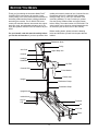
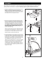
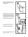
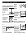
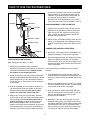
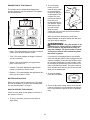
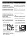
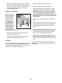
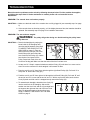
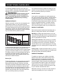
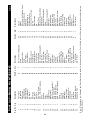
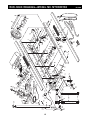
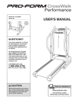
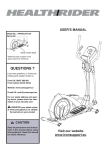
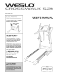
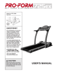
Model No. NTXC80182
Serial No.
Write the serial number in the
space above for future reference.
Serial
Number
Decal
QUESTIONS?
As a manufacturer, we are committed to providing complete
customer satisfaction. If you have
questions, or if parts are missing
or damaged, we will guarantee
complete satisfaction through
direct assistance from our factory.
TO AVOID DELAYS, PLEASE
CALL DIRECT TO OUR TOLLFREE CUSTOMER HOT LINE. The
trained technicians on our customer hot line will provide immediate assistance, free of charge to
you.
CUSTOMER HOT LINE:
1-888-825-2588
Mon.–Fri., 6 a.m.–6 p.m. MST
CAUTION
Read all precautions and instructions in this manual before using
this equipment. Save this manual
for future reference.
USER’S MANUAL
TABLE OF CONTENTS
IMPORTANT PRECAUTIONS . . . . . . . . . . . . . . . . . . . . . . . . . . . . . . . . . . . . . . . . . . . . . . . . . . . . . . . . . . . . . . . .2
BEFORE YOU BEGIN . . . . . . . . . . . . . . . . . . . . . . . . . . . . . . . . . . . . . . . . . . . . . . . . . . . . . . . . . . . . . . . . . . . . . .3
ASSEMBLY . . . . . . . . . . . . . . . . . . . . . . . . . . . . . . . . . . . . . . . . . . . . . . . . . . . . . . . . . . . . . . . . . . . . . . . . . . . . . .4
HOW TO ADJUST THE SKI EXERCISER . . . . . . . . . . . . . . . . . . . . . . . . . . . . . . . . . . . . . . . . . . . . . . . . . . . . . . .6
HOW TO USE THE SKI EXERCISER . . . . . . . . . . . . . . . . . . . . . . . . . . . . . . . . . . . . . . . . . . . . . . . . . . . . . . . . . .7
MAINTENANCE AND STORAGE . . . . . . . . . . . . . . . . . . . . . . . . . . . . . . . . . . . . . . . . . . . . . . . . . . . . . . . . . . . . .9
TROUBLESHOOTING . . . . . . . . . . . . . . . . . . . . . . . . . . . . . . . . . . . . . . . . . . . . . . . . . . . . . . . . . . . . . . . . . . . . .11
CONDITIONING GUIDELINES . . . . . . . . . . . . . . . . . . . . . . . . . . . . . . . . . . . . . . . . . . . . . . . . . . . . . . . . . . . . . .13
PART LIST . . . . . . . . . . . . . . . . . . . . . . . . . . . . . . . . . . . . . . . . . . . . . . . . . . . . . . . . . . . . . . . . . . . . . . . . . . . . . .14
EXPLODED DRAWING . . . . . . . . . . . . . . . . . . . . . . . . . . . . . . . . . . . . . . . . . . . . . . . . . . . . . . . . . . . . . . . . . . . .15
HOW TO ORDER REPLACEMENT PARTS . . . . . . . . . . . . . . . . . . . . . . . . . . . . . . . . . . . . . . . . . . . . .Back Cover
LIMITED WARRANTY . . . . . . . . . . . . . . . . . . . . . . . . . . . . . . . . . . . . . . . . . . . . . . . . . . . . . . . . . . . . . .Back Cover
IMPORTANT PRECAUTIONS
WARNING:
To reduce the risk of serious injury, read all precautions and instructions in
this manual before using the ski exerciser.
1. Read all instructions in this manual before
using the ski exerciser. Use the ski exerciser only as described in this manual.
become caught on the ski exerciser. Always
wear athletic shoes for foot protection.
8. The pulse monitor is not a medical device.
Various factors, including the user’s movement, may affect the accuracy of heart rate
readings. The pulse monitor is intended
only as an exercise aid in determining heart
rate trends in general.
2. It is the responsibility of the owner to
ensure that all users of the ski exerciser are
adequately informed of all precautions.
3. Use the ski exerciser indoors, away from
moisture and dust. Place the ski exerciser
on a level surface, with a mat beneath it to
protect the floor or carpet from damage.
9. Keep hands and feet away from moving
parts.
4. Inspect and tighten all parts regularly.
Replace any worn parts immediately.
10. Always dismount the ski exerciser before
adjusting the resistance of the skis.
5. Keep children under the age of 12 and pets
away from the ski exerciser at all times.
11. If you feel pain or dizziness at any time
while exercising, stop immediately and
begin cooling down.
6. The ski exerciser should not be used by
persons weighing more than 250 pounds.
12. The ski exerciser is intended for in-home
use only. Do not use the ski exerciser in a
commercial, rental, or institutional setting.
7. Wear appropriate clothing when exercising;
do not wear loose clothing that could
WARNING:
Before beginning this or any exercise program, consult your physician.
This is especially important for persons over the age of 35 or persons with pre-existing health problems. Read all instructions before using this product. ICON assumes no responsibility for personal
injury or property damage sustained by or through the use of this product.
NordicTrack is a registered trademark of ICON Health & Fitness, Inc.
2
BEFORE YOU BEGIN
reading this manual, please call our Customer Service
Department toll-free at 1-888-825-2588, Monday
through Friday, 6 a.m. until 6 p.m. Mountain Time
(excluding holidays). To help us assist you, please
note the product model number and serial number
before calling. The model number is NTXC80182. The
serial number can be found on a decal attached to the
ski exerciser (see the front cover of this manual).
Thank you for selecting the innovative NordicTrack®
CLASSIC PRO cross-country ski exerciser. Crosscountry skiing is one of the most effective exercises for
increasing cardiovascular fitness, building endurance,
and toning the muscles. The CLASSIC PRO crosscountry ski exerciser features ultra-smooth skis, upperbody arm cords, and adjustable resistance to let you
enjoy this dynamic exercise in the convenience of your
home.
Before reading further, please review the drawing
below and familiarize yourself with the parts that are
labeled.
For your benefit, read this manual carefully before
you use the ski exerciser. If you have questions after
Resistance Knob
Pulley
Arm Cord
Upper Body Arm
Console
Handgrip
Handlebar
Hip Pad
Console Wire
Pulse Monitor
Clothes Clip
Upright
Resistance Clamp
Resistance Strap
Upright Knobs
Incline Knob
Leg Pin
Flywheel
Leg
Ski
Kick Pad
Roller
3
ASSEMBLY
Place all parts of the ski exerciser in a cleared area and remove the packing materials; do not dispose of the
packing materials until assembly is completed. Assembly requires only the included flat wrench tool.
1. Attach the Leg Bracket (2) to the Front Frame (1) with
two M10 x 16mm Hex Screws (73) and two M10
Washers (72) as shown. Make sure that the ends of the
Leg Bracket angle away from the Front Frame and that
the indicated hole is in the position shown.
1
2
1
Hole
72
73
2. Insert a Leg (76) up into the square opening in either
end of the Leg Bracket (2). Align the second hole from
the bottom of the Leg with the hole in the Leg Bracket,
and insert the straight end of a Leg Pin (74) into the
holes. Make sure that the Leg Pin goes completely
through the holes and that the bent end of the Leg
Pin points toward the floor. Rotate the Leg Pin to
secure it around the Leg.
2
2
Stud
92
94
Slots
74
93
Slide an Incline Clamp (92) onto the indicated stud and
into the slots in the Leg Bracket (2). Tighten an Incline
Knob (93) with an Incline Washer (94) onto the stud.
76
76
Attach the other Leg (76) in the same way.
3. Lift the Upper Body Arm (27) slightly so it will not catch
on the Front Frame (1), and raise the Upright (16) to the
position shown. The Upright will snap into place when it
is positioned correctly. Make sure that the M8 Push Nut
(18) is between the Upright and the Front Frame.
Tighten the two Upright Knobs (17). Note: Each Upright
Knob functions like a wrench. Turn the Upright Knob
clockwise, pull it away from the Upright (16), turn it
counterclockwise, push it toward the Upright, and then
turn it clockwise again. Repeat this procedure until the
Upright Knob is tight.
3
27
16
17
18
1
17
4
4. Raise the Upper Body Arm (27) to position as shown.
Make sure that the Snap Buttons (40) are fully
extended and locked into position on both sides of
the Hip Pad Slide (42).
4
27
40
5. The Console (66) requires two “AA” batteries. Alkaline
batteries are recommended. See the inset drawing.
Locate the Battery Door (89) on the back of the Console.
Press the indicated tab on the Battery Door and remove
the Battery Door. Press two batteries into the battery
compartment, with the negative ends of the batteries
touching the springs. Then, reattach the Battery Door.
42
5
66
Attach the Console (66) to the Upper Body Arm (27) by
firmly pressing it into place in the desired location.
27
89
66
Tab
Batteries
6. Plug the Console Wire (47) and the Pulse Monitor (49)
into the indicated jacks on the Console (66).
6
66
Speed
Pulse
See the inset drawing. Plug the other end of the
Console Wire (47) into the jack on the Upright (16).
49
47
47
7. Make sure that all parts are tightened before you use the
ski exerciser. To protect the floor from damage, place a
mat beneath the ski exerciser.
5
16
HOW TO ADJUST THE SKI EXERCISER
For greater
adjustments
in the length
of the Arm
Cord (23),
add one loop
23
23
of the Arm
Cord around
the pulley as
shown, or remove one loop from the pulley.
HOW TO ADJUST THE RESISTANCE OF THE SKIS
To vary the intensity of your exercise, you can change
your exercise pace, use the arm cord (see the section
below), or adjust the resistance of the skis. CAUTION:
Always dismount the ski exerciser before adjusting the resistance of the skis.
To increase the resistance
of the skis, slide the
Resistance Clamp (85) to a
higher position on the
Upright (16). To decrease
the resistance, slide the
Resistance Clamp to a
lower position.
85
HOW TO ADJUST THE POSITION OF THE HIP PAD
16
Loosen the Adjustment
53
Knob (41) on each side of
the Hip Pad Slide (42), and
slide the Hip Pad Slide to
the desired position. The
Hip Pad (53) should be at
hip level, about one inch
42
below your navel. The Hip
41
Pad should be high
enough that it does not
restrict leg movement, and
low enough that it does not press against your
abdomen. Firmly retighten both Adjustment Knobs.
HOW TO ADJUST THE RESISTANCE OF THE ARM
CORD
The resistance of the Arm
39 88
Cord (23) can be adjusted
with the Resistance Knob
(39) above the Pulley (35).
Turn the Knob clockwise to
increase the resistance, or
35
counterclockwise to
decrease the resistance.
23
Note: As you turn the
Resistance Knob, the numbered Resistance Scale
Decal (88) will protrude through the Knob to show the
resistance setting.
HOW TO ADJUST THE ELEVATION OF THE SKI
EXERCISER
Increasing the elevation of the ski exerciser will simulate uphill skiing. This will further develop the quadriceps muscles on the fronts of your thighs, elevate your
heart rate more quickly, and provide a more intense
workout.
WARNING:
The Pulley (35) will get hot
during use. Avoid touching the Pulley immediately
after use.
To adjust the elevation,
first loosen the Incline
76
Knob (93) in front of one
93
of the Legs (76). Insert the
straight end of a Leg Pin
(74) into the hole in the
2
Leg Bracket (2) and one of
74
the holes in the Leg. Make
sure that the Leg Pin
goes completely through
the holes and that the
bent end of the Leg Pin points toward the floor.
Rotate the Leg Pin to secure it around the Leg.
Retighten the Incline Knob.
HOW TO ADJUST THE LENGTH OF THE ARM CORD
When the Arm
Cord (23) is
adjusted to the
proper length,
23
your arms
24
Knot
should extend
just behind your
hips when you
use the Arm Cord. To adjust the length of the Arm
Cord, retie the knot inside each Handgrip (24).
Repeat this process with the other Leg (not shown).
Make sure that both Legs are at the same height.
6
HOW TO USE THE SKI EXERCISER
on the skis at all times. Note: There is no defined
range of motion for your stride. Increase the ski
resistance if you slide away from the hip pad. As
you exercise, you may want to increase or
decrease your stride depending on your comfort
level. Once this motion feels comfortable, move on.
Arm Cord
Handlebar
Handgrip
ADD ARM SWINGS TO THE LEG MOTION
Hip Pad
1. Continue your leg motion. Keep one hand on the
handlebar or the hip pad for balance. Swing your
other arm at your side. When your left leg is forward, your left arm should be back. Repeat this
process with your other arm.
Resistance Clamp
2. When you are comfortable swinging each arm separately, try swinging both arms. Swing your arms
naturally. Practice this motion until it feels comfortable.
Resistance Strap
COMBINE THE ARM AND LEG MOTIONS
Flywheel
1. Set the arm cord resistance at a comfortable level.
Grasp the handgrips. Continue your leg motion.
Ski
2. Pull the handgrips through your natural arm swing.
When your right leg is forward, your right hand
should be back; when your left leg is forward, your
left hand should be back. Practice this motion until
it feels comfortable.
START WITH LEG MOTION ONLY
Note: See page 6 for steps 1, 2, and 3.
1. Adjust the ski resistance and the elevation.
(Beginners may prefer to start with the ski exerciser
in the lowest elevated position.) Make sure that
the flywheel is not touching the floor.
Use the tips below to coordinate the arm and leg
motions:
1. If combining the arm and leg motions is difficult,
keep practicing the leg motion. Incorporate the arm
motion only when you feel comfortable with the leg
motion.
2. Adjust the hip pad to the proper height. Make sure
that the hip pad adjustment knobs are tight. The hip
pad is designed for you to push against; however,
do not lean over it. There may be some movement
to the upright.
2. When you incorporate the arm motion, try to swing
your arms naturally. Allow one arm to pull the other
arm forward. Keep the arm cord taught.
3. Hold the handlebar or the hip pad for balance. Do
not lean forward. Keep your weight on your feet
and your back straight. Increase the ski resistance if you slide away from the hip pad.
3. Keep your waist in contact with the hip pad at all
times to hold back your forward motion. If you feel
that you are sliding away from the hip pad,
increase the ski resistance.
4. Begin to ski. Push your right foot back, and then
your left. Do not pull your right foot forward until the
left is pushing back. Do not bring either foot in
front of your body. Continue to move both feet
with a smooth walking motion. Start with short
strides. You will feel the ski resistance as you move
your foot backward. Let your heel rise naturally at
the back of your stride. Keep the balls of your feet
4. Resistance is felt only when you push your feet
backward. Always keep your weight on the ski you
are pushing backward. Avoid leaning forward. Keep
your weight over your feet, your shoulders back,
and your head up. Find a focal point; this will help
you keep your head up and your back straight.
7
2. To use the pulse
mode, you must
wear the pulse moniPulse
tor. Plug the pulse
Monitor
monitor into the jack
on the bottom of the
console. Rub your
left ear lobe several
times with your
thumb and index finClip
ger and then clip the
pulse monitor onto
your left ear lobe.
Slide the metal
clothes clip onto your collar to prevent excessive
movement of the wire.
DESCRIPTION OF THE CONSOLE
The console has five independent displays that
provide continuous exercise feedback. The displays
are described below.
When your pulse is detected, the small heartshaped indicator in the pulse display will flash and
your pulse will be displayed.
WARNING:
The pulse monitor is not
a medical device. Various factors, including the
user’s movement, may affect the accuracy of
heart rate readings. The pulse monitor is intended only as an exercise aid in determining heart
rate trends in general.
• Pulse—This mode displays your pulse in beats per
minute when the pulse monitor is worn.
• Time—This mode displays the length of time that
you have exercised.
If your pulse is not displayed after a few seconds,
make sure that the pulse monitor is plugged into the
console. In addition, make sure that the pulse monitor is properly attached to your left ear lobe. It may
be necessary to reposition the pulse monitor a few
times to find the best position. The pulse monitor is
more accurate when used on your left ear lobe and
when you are standing still.
• Speed—This mode displays your approximate
pace, in miles per hour.
• Calories—This mode displays the approximate
number of calories you have burned.
• Distance—This mode displays the approximate distance you have skied, in miles.
3. To reset the display,
press the reset button.
BATTERY INSTALLATION
Before the console can be operated, two “AA” batteries must be installed. If you have not installed batteries, see assembly step 5 on page 5.
4. To turn off the power, simply wait for a few minutes.
If the ski exerciser is not used and the console button is not pressed, the power will turn off automatically.
HOW TO OPERATE THE CONSOLE
If there is a thin sheet of clear plastic on the face of
the console, remove it.
1. To turn on the power, press the reset button or
begin skiing.
8
MAINTENANCE AND STORAGE
Inspect and tighten all parts each time you use the ski
exerciser.
4. Wipe any excess oil away from the area around the
resistance pad. Tighten the resistance knob.
CLEANING THE SKI EXERCISER
Inspect the bottom of the pulley. If the resistance disk
(located above the resistance pad) has grooves worn
into it, it should be replaced. See the back of this manual for instructions on how to order replacement parts.
Wipe the ski exerciser with a clean, dry cloth after
each workout to remove perspiration and dirt. A household window cleaner may be used to clean the chrome
and black metal surfaces.
CARING FOR THE RESISTANCE STRAP AND
FLYWHEEL
Wipe the wood with a clean, dry cloth to remove perspiration and dirt after each use. Use a wood furniture
polish or wax to protect the wood finish and prevent
drying.
Resistance strap and flywheel maintenance should be
performed once a month at the same time. Follow the
steps below.
1. Place a cloth or a piece of plastic under the ski
exerciser to protect your floor.
If the bottoms of the skis become marked from contact
with the drive rollers, wipe them with a clean, dry cloth.
Use mineral spirits to remove stubborn marks. For a
smooth gliding action, carefully rub paraffin wax only
on the sides of the skis. NEVER polish or wax the
bottoms of the skis. The skid plates built into the
sides of the skis are designed to wear down and leave
a light coating on the sides of the skis. These plates
do not need to be replaced.
2. Set the ski resistance to the lowest setting.
3. Slide the resistance strap off the side of the flywheel.
4. Wipe the surface of the flywheel with a clean cloth
dampened with rubbing alcohol.
LUBRICATING THE RESISTANCE PAD
5. Check the groove of the flywheel for any rust or
corrosion.
The leather resistance pad beneath the pulley has
been oiled for quiet, smooth braking action. However,
the pad will require re-oiling if it dries due to its surroundings. We recommend inspecting the resistance
pad every three months.
6. Use fine to very fine steel wool to spot rub any rust
or corrosion. Clean the entire flywheel with steel
wool if necessary.
1. Place a cloth or a piece of plastic under the ski
exerciser to protect your floor.
2. See the inset
drawing. Inspect
the Thrust Washer
(37). Lightly oil the
Thrust Washer if it
is not greasy.
7. Wipe the flywheel with a clean, dry cloth to remove
any residue. NEVER place oil between the resistance strap and the flywheel; this will damage the
resistance strap.
39
8. Slide the “U”
Bolt Cover (64)
54
to the right and
67
check the
tightness of
64
the M6 Nuts
67
(67) on the
right side of
the Flywheel
(54). If necessary, tighten
the Nuts evenly with a wrench. CAUTION: Do not overtighten
the Nuts; this can break the “U” Bolt.
35
Fully loosen but
37
32
do not remove the
Resistance Knob
(39). Lift the
Pulley (35) and
roughen the surface of the leather Resistance Pad
(32) with 100-grit sandpaper or a file.
3. Spread one or two drops of light household oil on
the resistance pad. DO NOT OVER-OIL. Excess oil
may spray out when the pulley is spinning. Place a
pencil between the pulley and the resistance pad
and let the oil absorb overnight.
9
9. Slide the resistance strap back onto the flywheel.
Note: If the resistance strap is frayed on both sides,
it may be necessary to replace it. See the back
cover of this manual for instructions on how to
order replacement parts.
GENERAL LUBRICATION
If the front or rear
Rollers (15) begin to
squeak, a drop of
light household oil
may be needed on
the Roller Axles
(70). Important:
The drive rollers
located near the
flywheel are internally lubricated
and should NOT
be oiled. Follow the
instructions below to apply oil.
Flywheel
Oil
Oil
1. Remove the batteries from the console.
2. Slide the resistance strap off the flywheel.
3. Lightly coat the groove of the flywheel with light
household oil to protect the metal from corrosion.
IMPORTANT: Never place oil on the resistance
strap. Only the flywheel should be oiled and
then cleaned before the resistance strap is reattached. Do not place the resistance strap on the
oiled flywheel.
4. Loosen the two adjustment knobs on the hip pad
slide.
70
15
1. Place a cloth or a piece of plastic under the ski
exerciser to protect your floor.
2. Put a drop of light household oil on each side of
each roller, and then spin each roller.
5. Move the hip pad slide so the top is about seven
inches below the top of the upright. Retighten both
of the adjustment knobs and pivot the hip pad
upward.
6. Support the upper body arm with one hand. Use
the other hand to depress the two snap buttons on
either side of the hip pad slide. Lower the upper
body arm until it rests against the upright.
7. Hold the upright with one hand. Loosen the two
upright knobs. Lower the upright until it rests on the
base. The hip pad should just touch the tops of the
skis.
STORAGE
Set the ski resistance to the lowest setting and remove
any accessories before folding and storing your ski
exerciser. When storing the ski exerciser for more than
30 days, we recommend the following:
Upon removal from storage, clean the flywheel with
rubbing alcohol. Slide the resistance strap back onto
the flywheel.
10
TROUBLESHOOTING
Most ski exerciser problems can be solved by following the steps below. Find the problem that applies,
and follow the steps listed. If further assistance is needed, please call our Customer Service
Department.
PROBLEM: The console does not function properly.
SOLUTION: a. Make sure that both ends of the console wire are fully plugged in (see assembly step 6 on page
5).
b. If the console does not function properly, or if the display becomes faint, the batteries should be
replaced. See assembly step 5 on page 5 for installation instructions.
PROBLEM: The arm cords are tangled.
WARNING: The pulley will get hot during use. Avoid touching the pulley immediately after use.
SOLUTION: a. Detach the handgrips by untying the
knots inside of the handgrips and
removing the M6 washers (see HOW
28
TO ADJUST THE LENGTH OF THE
28
28
ARM CORD on page 6). Take the
ends of the Arm Cord (23) out of the
35
Small Pulleys (28) and unwind the
Arm Cord from the Pulley (35). Notice
23
how the Arm Cord goes into the
Pulley. Drape both ends of the Arm
Cord over the hip pad. Make sure that the ends of the Arm Cord are even.
28
A
B
b. Locate cord “A.” Wrap it counterclockwise around the Pulley (35) until there is no more cord to
wind. Do not be concerned if it looks tangled; it will smooth out later.
c. Pass the end of cord “A” from left to right through the right Small Pulley (28). Pull cord “A” to
wrap cord “B” around the Pulley (35).
d. Feed the end of cord “B” from right to left through the left Small Pulley (28). Pull cord “B” until
the end of cord “B” is even with the end of cord “A.” With a cord in each hand, work the Arm
Cord (23) back and forth until it is wrapped evenly around the Pulley (35).
e. To reattach each handgrip, thread the Arm Cord (23)
into the small hole in the handgrip, slide an M6
washer onto the Arm Cord, and tie a figure-eight knot
as shown at the right near the end of the Arm Cord.
Note: To adjust the length of the Arm Cord, see
HOW TO ADJUST THE LENGTH OF THE ARM
CORD on page 6.
11
23
PROBLEM: The arm cord assembly makes a chattering or screeching sound or the resistance knob
loosens.
SOLUTION: a. Check the order of the parts in the pulley assembly, and confirm that all parts are present. The
parts from the pulley to the resistance knob should be as follows: M10 washer, thrust washer,
M10 washer, and spring.
b. Roughen the surface of the resistance pad with 100-grit sandpaper. Oil the leather resistance
pad with one or two drops of light household oil. Spread the oil over the resistance pad.
c. Oil the M10 washers and the thrust washer if needed.
PROBLEM: The flywheel and/or the resistance strap offers no resistance.
SOLUTION: a. Check the routing of the resistance strap.
b. Make sure that the flywheel is tight. Remove the “U” bolt cover from the flywheel (see step 8 on
page 9). Evenly tighten the two M6 nuts located on the right side of the flywheel.
PROBLEM: The skis slip.
SOLUTION: a. Wipe off any excess oil.
b. Clean the bottoms of the skis with a dry cloth and a small amount of mineral spirits or paint
thinner.
c. Make sure that the flywheel is tight. Remove the “U” bolt cover from the flywheel (see step 8 on
page 9). Evenly tighten the two M6 nuts located on the right side of the flywheel.
PROBLEM: The rollers squeak or stick.
SOLUTION: See GENERAL LUBRICATION on page 10.
12
CONDITIONING GUIDELINES
For maximum fat burning, adjust the intensity of your
exercise until your heart rate is near the middle number in your training zone as you exercise.
The following guidelines will help you to plan your
exercise program. Remember that proper nutrition and
adequate rest are essential for successful results.
WARNING:
Before beginning this or
any exercise program, consult your physician.
This is especially important for individuals over
the age of 35 or individuals with pre-existing
health problems.
Aerobic Exercise
If your goal is to strengthen your cardiovascular system, your exercise must be “aerobic.” Aerobic exercise
is activity that requires large amounts of oxygen for
prolonged periods of time. This increases the demand
on the heart to pump blood to the muscles, and on the
lungs to oxygenate the blood. For aerobic exercise,
adjust the intensity of your exercise until your heart
rate is near the highest number in your training zone.
EXERCISE INTENSITY
Whether your goal is to burn fat or to strengthen your
cardiovascular system, the key to achieving the
desired results is to exercise with the proper intensity.
The proper intensity level can be found by using your
heart rate as a guide. The chart below shows recommended heart rates for fat burning, maximum fat burning, and cardiovascular (aerobic) exercise.
WORKOUT GUIDELINES
Each workout should include three important parts: a
warm-up, training zone exercise, and a cool-down.
Warming up—Begin each workout with 5 to 10 minutes of stretching and light exercise. A proper warm-up
increases your body temperature, heart rate and circulation in preparation for exercise.
Training zone exercise—After warming up, increase
the intensity of your exercise until your heart rate is in
your training zone for 20 to 30 minutes. (During the
first few weeks of your exercise program, do not keep
your heart rate in your training zone for longer than 20
minutes.)
To find the proper heart rate for you, first find your age
at the top of the chart (ages are rounded off to the
nearest ten years). Next, find the three numbers below
your age. The three numbers are your “training zone.”
The lowest number is the recommended heart rate for
fat burning; the middle number is the heart rate for
maximum fat burning; and the highest number is the
heart rate for aerobic exercise.
Cooling down—Finish each workout with 5 to 10 minutes of stretching. This will increase your flexibility and
will help to prevent post-exercise problems.
EXERCISE FREQUENCY
To maintain or improve your condition, plan three
workouts each week, with at least one day of rest
between workouts. Five minutes of exercise, four
times a day, may be sufficient when you begin an
exercise program. Slowly increase your workout time
as your fitness level improves. After a few months of
regular exercise, you may complete up to five workouts each week, if desired. Find the best time of day
for your workouts, and then stick with it.
Burning Fat
To burn fat effectively, you must exercise at a relatively low intensity level for a sustained period of time.
During the first few minutes of exercise, your body
uses easily accessible carbohydrate calories for energy. Only after the first few minutes of exercise does
your body begin to use stored fat calories for energy. If
your goal is to burn fat, adjust the intensity of your
exercise until your heart rate is near the lowest number in your training zone as you exercise.
Remember, the key to success is to make exercise a
regular and enjoyable part of your everyday life.
13
14
2
4
1
2
1
1
1
1
1
1
2
4
1
1
2
4
2
2
1
14
15
16
17
18
19
20
21
22
23
24
25
26
27
28
29
30
31
32
Front Frame
Leg Bracket
Rear Frame
Left Side Board
Right Side Board
Cross Member
Top Board
Ski
Foot Plate
Toe Piece
Skid Plate
M5 x 16mm Screw
M3.5 x 32mm Self-tapping
Screw
Kick Pad
Roller
Upright
Upright Knob
M8 Push Nut
M8 x 70mm Carriage Bolt
Reed Switch/Wire
Reed Switch Bracket
M3.5 x 16mm Self-tapping
Screw
Arm Cord
Handgrip
M6 Washer
Upright Endcap
Upper Body Arm
Small Pulley
“C” Clip
Pulley Axle
Resistance Bracket
Resistance Pad
Description
4
1
1
2
1
1
1
1
2
1
2
2
2
2
1
4
1
2
1
1
1
1
1
2
1
1
4
4
2
1
1
1
1
33
34
35
36
37
38
39
40
41
42
43
44
45
46
47
48
49
50
51
52
53
54
55
56
57
58
59
60
61
62
63
64
65
Key No. Qty.
M3.5 x 16mm Self-tapping
Screw
Resistance Disc
Pulley
M10 Washer
Thrust Washer
Spring
Resistance Knob
Snap Buttons
Adjustment Knob
Hip Pad Slide
Round Endcap
M8 x 40mm Carriage Bolt
M6 Jam Nut
M6 x 40mm Bolt
Console Wire
M6 x 20mm Screw
Pulse Monitor
Bumper
Pad Bracket
Pad Cover
Hip Pad
Flywheel
Flywheel Axle
Flywheel Bearing
Magnet Bracket
Magnet
M16 Washer
Large Nylon Spacer
Drive Roller w/Bearing
M5 Set Screw
Axle Clamp w/Set Screw
“U” Bolt Cover
M6 “U” Bolt
Description
66
67
68
69
70
71
72
73
74
75
76
77
78
79
80
81
82
83
84
85
86
87
88
89
90
91
92
93
94
95
96
#
#
1
2
8
4
4
2
2
2
2
2
2
2
1
9
8
2
2
2
1
1
1
2
1
1
2
1
2
2
2
8
1
1
1
Key No. Qty.
Console
M6 Nut
M5 x 16mm Self-tapping Screw
Small Nylon Spacer
Roller Axle
Self-Backing Nut
M10 Black Washer
M10 x 16mm Hex Screw
Leg Pin
Square Endcap
Leg
Rubber Foot
M8 x 45mm Hex Head Bolt
M8 Flange Nut
M8 x 35mm Carriage Bolt
Wheel
M6 x 42mm Carriage Bolt
M6 Hex Nut
Resistance Strap
Resistance Clamp
Resistance Spring
Foam Grip
Resistance Scale Decal
Battery Door
Bronze Bushing
M5 x 12mm Screw
Incline Clamp
Incline Knob
Incline Washer
M5 Black Washer
M5 Washer
Flat Wrench Tool
User’s Manual
Description
R0104A
Note: “#” indicates a non-illustrated part. Specifications are subject to change without notice. See the back cover of this manual for information about ordering
replacement parts.
1
1
1
1
1
2
2
2
2
2
4
8
4
1
2
3
4
5
6
7
8
9
10
11
12
13
Key No. Qty.
PART LIST—MODEL NO. NTXC80182
15
93
94
16
92 75
17
18
29
19
96
91
90
77
76
74
36
72
45
75
22
93
72
1
92
73
2
15
71
80
94
24
28 27
68
25 40
5
41
74
71
70
52
51
53
69
6
17
68
59
60
11
13
48
42 46
9
44
10
43
48
7
79
15
79
13
50
50
35
87
34
43
33 66
44
31
45
87
29
30
46
89
78
23
90
21
73
20
30
33
29 32
28
31
26
88
39
38
41
37
61
56
7
60
59
6
15
63
80
62 25
67
68
81
79
8
85
13
64
4
65
68
14
86
11
95
12
83
70
15
10
12
81 82
3
54
84
11
13
69
14
57
8
9
59
60
61
58
47
80
60
55
49
59
56
EXPLODED DRAWING—MODEL NO. NTXC80182
R0104A
HOW TO ORDER REPLACEMENT PARTS
To order replacement parts, call our Customer Service Department toll-free at 1-888-825-2588, Monday through
Friday, 6 a.m. until 6 p.m. Mountain Time (excluding holidays). Mention the following information when calling.
• The MODEL NUMBER of the product (NTXC80182)
• The NAME of the product (NordicTrack® CLASSIC PRO cross-country ski exerciser)
• The SERIAL NUMBER of the product (see the front cover of this manual)
• The KEY NUMBER and DESCRIPTION of each part (see page 14)
LIMITED WARRANTY
WHAT IS COVERED—The entire NordicTrack® CLASSIC PRO cross-country ski exerciser (“Product”) is warranted to be
free of all defects in material and workmanship.
WHO IS COVERED—The original purchaser or any person receiving the Product as a gift from the original purchaser.
HOW LONG IS IT COVERED—ICON Health & Fitness, Inc. (“ICON”), warrants the product for one year after the date of
purchase. Labor is covered for one year.
WHAT WE DO TO CORRECT COVERED DEFECTS—We will ship to you, without charge, any replacement part or component, providing the repairs are authorized by ICON first and are performed by an ICON trained and authorized service
provider, or, at our option, we will replace the Product.
WHAT IS NOT COVERED—Any failures or damage caused by unauthorized service, misuse, accident, negligence, improper assembly or installation, alterations, modifications without our written authorization or by failure on your part to use, operate, and maintain as set out in your User’s Manual (“Manual”).
WHAT YOU MUST DO—Always retain proof of purchase, such as your bill of sale; store, operate, and maintain the Product
as specified in the Manual; notify our Customer Service Department of any defect within 10 days after discovery of the defect;
as instructed, return any defected part for replacement or, if necessary, the entire product, for repair.
USER’S MANUAL—It is VERY IMPORTANT THAT YOU READ THE MANUAL before operating the Product. Remember to
do the periodic maintenance requirements specified in the Manual to assure proper operation and your continued satisfaction.
HOW TO GET PARTS AND SERVICE—Simply call our Customer Service Department at 1-888-825-2588 and tell them your
name and address and the serial number of your Product. They will tell you how to get a part replaced, or if necessary,
arrange for service where your Product is located or advise you how to ship the Product for service. Before shipping, always
obtain a Return Authorization Number (RA No.) from our Customer Service Department; securely pack your Product (save
the original shipping carton if possible); put the RA No. on the outside of the carton and insure the product. Include a letter
explaining the product or problem and a copy of your proof of purchase if you believe the service is covered by warranty.
ICON is not responsible or liable for indirect, special or consequential damages arising out of or in connection with the use
or performance of the product or damages with respect to any economic loss, loss of property, loss of revenues or profits,
loss of enjoyment or use, costs of removal, installation or other consequential damages of whatsoever nature. Some states
do not allow the exclusion or limitation of incidental or consequential damages. Accordingly, the above limitation may not
apply to you.
The warranty extended hereunder is in lieu of any and all other warranties and any implied warranties of merchantability or
fitness for a particular purpose is limited in its scope and duration to the terms set forth herein. Some states do not allow limitations on how long an implied warranty lasts. Accordingly, the above limitation may not apply to you.
No one is authorized to change, modify or extend the terms of this limited warranty. This warranty gives you specific legal
rights and you may have other rights which vary from state to state.
ICON HEALTH & FITNESS, INC., 1500 S. 1000 W., LOGAN, UT 84321-9813
Part No. 205436 R0104A
Printed in China © 2004 ICON Health and Fitness, Inc.