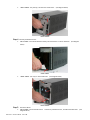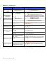
1
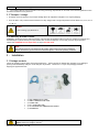
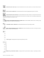
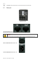
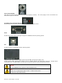
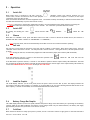
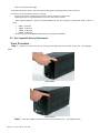
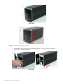
User manual Ace Series Uninterruptible Power Supply 600-1000-1500-2000 VA UL-version POWERVAR 1450 Lakeside Drive Waukegan, IL 60085 ACE Series Telephone 847-596-7000 Fax 847-596-7132 Website www.powervar.com The ABCs of Power Conditioning USER MANUAL ACE Series Uninterruptible Power Supply 600 - 1000 - 1500 - 2000 VA UL-version The POWERVAR ACE Series UPS, uninterruptible power supply, protects your equipment from all forms of power interference, including complete power failures. Please keep this manual in a safe place for future reference and carefully read the important safety instructions in chapter 1 before installation and start-up of the UPS. All rights reserved. Reproduction in whole or in parts without the prior written consent of POWERVAR is prohibited. The illustrations and plans describing the equipment are intended as general reference only and are not necessarily complete in every detail. The content of this manual may be subject to change without prior notice. A01-00005 ACE Series Owner’s Manual 1 Rev. A 0309 Contents 1 Important safety instructions ........................................................................... 1 1.1 Save these instructions 1.2 Safety rules Introduction ...................................................................................................... 2 2 2.1 Introduction 2.2 Intended use 2.3 Transport / storage 2.4 Warranty and RMA process Installation ........................................................................................................ 3 3 3.1 Package contents 3.2 Installation rules 3.3 Installation procedure 6 7 Placement 3.3.2 Connecting interface devices 3.3.3 Charge the battery 3.3.4 Connect to utility supply 3.3.5 Check the site wiring fault indicator 3.3.6 Advanced monitoring software Layout, Control Panel ....................................................................................... 5 4 5 3.3.1 4.1 Front LED operating panel 4.2 Back panel Operation … … … … … … … … … … … … … … … … … … … … … … … … … … … … … … … … … … … … … … ….. … … … … … … …. … … … … … … … … … … …..8 5.1 Switch ON 5.2 Switch OFF 5.3 Silence 5.4 Self test 5.5 Load Bar Graphic 5.6 Battery Charge Bar Graphic 5.7 Cold Start 5.8 Shutdown Mode Alarms .............................................................................................................. 10 6.1 BACKUP (slow alarm) 6.2 Low Battery (rapid alarm) 6.3 Fault (continuous alarm) Software and Interface Port ............................................................................ 10 7.1 Power Monitoring Software 7.2 Computer interface SERIAL port pin configuration ACE Series – Owner’s Manual – 03/17/09 8 9 7.3 Computer interface USB port configuration 7.4 Computer Network Security Recommendations Maintenance and Storage ................................................................................ 13 8.1 Maintenance 8.2 Storage Conditions 8.3 Extended Storage Conditions Battery … … … … … … … … … … … … … … … … … … … … … … … … …. … … … … … … … … … … … … … … … … … … …..14 9.1 Battery Life 9.2 Battery Rules 9.3 Safety precautions 9.4 Hot Swappable Battery Replacement Tower Procedure Appendix A: Troubleshooting … … … … … … … … … … … … … … … … … … … … … … … … … … … … … … … …..21 Appendix B: Specifications … … … … … … … … … … … … … … … … … … … … … … … … … … … … …. … … … … …22 ACE Series – Owner’s Manual – 03/17/09 1- Important safety Instructions 1.1 Save these instructions This manual contains important instructions that should be followed during installation and maintenance of the UPS. It also gives all necessary information about the correct use of the UPS. Before attempting to install and start up the UPS, carefully read this manual. Keep this manual next to the unit for future reference. Full understanding of and compliance with the safety instructions and warnings contained in this manual are CONDITIONS to avoid any dangerous situation during installation, operation and maintenance work, and to preserve the maximum reliability of the UPS system. POWERVAR refuses any responsibility in case of non-observance, unauthorized alterations or improper use of the delivered UPS. The instructions in this manual pertain to ACE Series UPS models. While every care has been taken to ensure the completeness and accuracy of this manual, POWERVAR accepts no responsibility or liability for any loss or damage resulting from the use of the information contained in this document. Due to technical improvements, some of the information contained in this manual may be changed without notice. This document shall not be copied nor reproduced without the permission of POWERVAR. 1.2 Safety rules CAUTION! RISK OF ELECTRIC SHOCK. The UPS contains batteries. The load outlets may be electrically live, even when the UPS is disconnected from the utility. The UPS contains potentially hazardous voltages. Do not open the unit; there are no user serviceable parts inside. All maintenance and service work, except replacement of the batteries, should be performed by qualified service personnel. After switching UPS unit OFF, wait two (2) minutes for the DC capacitors to discharge. Lethally high voltage may remain at the terminals of the electrolytic capacitors. Be aware that the inverter can restart automatically after the input voltage is restored. CAUTION There may be damage to the equipment if procedures and practices are not strictly observed and followed. NOTE Do not attempt to service the UPS unless you have had proper training. Refer all maintenance and servicing to properly qualified, skilled and competent service personnel. CAUTION (Non-isolated Battery supply) Risk of electric shock, battery circuit is not isolated from AC input; hazardous voltage may exist between battery terminals and ground. Test before servicing. Remove watches, rings or other metal objects. Use insulated tools. WARNING Intend for installation in a controlled environment. CAUTION Do not dispose of batteries in a fire, they may explode. Do not open or mutilate the battery, released electrolyte is harmful to the skin and eyes. CAUTION To reduce the risk of fire, connect only to a circuit provided with 20 amperes maximum branch circuit overcurrent protection in accordance with the National Electric Code, ANSI/NFPA. Qualified, skilled personnel are persons who (because of their training, experience, and position as well as their knowledge of appropriate standards, regulations, health and safety requirements and working conditions) are authorized to be responsible for the safety of the equipment, at all times while carrying out their normal duties and are therefore aware of, and can report, possible hazards. ACE Series – Owner’s Manual – 03/17/09 2- Introduction 2.1 Introduction The ACE Series is a line interactive uninterruptible power supply (UPS) which generates a true sine wave output, that protects your equipment from power anomalies, including complete power failures. The ACE Series UPS is based on microprocessor control. The line-interactive UPS provides pure, reliable AC power to the critical loads - protecting them from utility power blackout, swells, sags, surges and interference. Critical loads include sensitive medical instruments, computers, telecommunication systems, and industrial equipment. Under normal power conditions, the line-interactive design enables the system to adjust and filter power fluctuations continuously and automatically. In the event of power anomaly, it can provide immediate back-up power from the batteries without any interruption. Complete transfer will be achieved within six (6) milliseconds, with no interruption. In addition, when the utility power is connected, the battery charger would work automatically even when UPS power switch is OFF. Furthermore, in order to save battery energy, UPS can automatically turn the charger OFF under backup mode if none of the connected loads are operating. The visual and audible indications of the UPS Advanced Battery Management algorithms present the battery’s status including capacity degree and battery condition. The self-test function can detect a weak battery before it is put into service. The UPS normally performs a self-test at power up and manual self-test condition. Self-test function can be initiated manually with the ON/TEST switch at any time. 2.2 Intended use x Uninterruptible Power Supplies (UPS) are designed to protect sensitive electronic equipment such as sensitive medical instruments, computers, telecommunication systems, and industrial equipment, from all forms of power interference, including complete power failure. CAUTION DO NOT plug household appliances such as electric heaters, toasters or vacuum cleaners into the UPS. The UPS output is intended for use with electronic loads such as computers and ACE Series – Owner’s Manual – 03/17/09 telecommunications equipment. x The technical data as well as information concerning connecting requirements can be found on the UPS rating label and in this document and shall be strictly observed. 2.3 Transport / storage x No liability can be accepted for any transport damage when the equipment is shipped in non-original packaging. x Store the UPS in a dry location with the batteries in a fully charged state. Storage temperature must be within 5qF (-15 qC) to 113 qF (+45 qC). CAUTION In case of storage, pay attention to: 2.4 Warranty and RMA Process POWERVAR, operating through its authorized agents, warrants that the standard products will be free of defects in materials and workmanship for a period of twenty-four (24) months after the date of shipment, or such other period as may be specified. Contact the POWERVAR Service Department for help at 847-596-7000. NOTE This warranty does not cover failures of the product, which result from incorrect installation, misuse, alterations by persons other than authorized agents, or abnormal operating conditions. 3 - Installation 3.1 Package contents Inspect the package contents against the supplied packing slip. Inspect the UPS for damage after unpacking. If any damage is present please immediately notify the carrier and place of purchase. Please save or recycle the packaging materials! Shipping kit supplied with UPS: x x x x x x (1) USB COMMUNICATION CABLE (1) SERIAL COMMUNICATION CABLE (1) POWER CORD (1) RJ11 TELEPHONE CORD (1) CD SOFTWARE WITH IMBEDDED USER MANUAL (1) USER MANUAL WARNING In case of recognizable damage: DO NOT connect any voltage to the unit ACE Series – Owner’s Manual – 03/17/09 DO NOT put the unit into operation IMPORTANT Before making any connection and switching on the ACE Series UPS, please check the following conditions: x x Utility supply is 120 Volts ± 10 % and 50/60Hz ± 5 %, Auto Sensing Total power demand of the connected load does not exceed the rated output power of the ACE Series UPS (the rear panel nameplate of the UPS shows the model, and load ratings). 3.2 Installation rules x x x The UPS must be powered from a single-phase grounded utility supply. Do not use extension cords. Avoid locations that are excessively humid, near water, near heat sources or in direct sunlight. The ambient temperature should not exceed 104qF (40°C). Optimal battery lifetime is obtained if the ambient temperature does not exceed 77qF (25°C). x It is important that ventilation air can move freely around and through the unit. Allow 1-inch (2.5cm) clearance on each side of the ACE Series UPS. x Do not block the UPS air vent. x Install the UPS in a protected area free of excessive dust. Do not operate the UPS where temperature and humidity is out of the specified limits. The unit must be placed in a sufficiently ventilated area; the ambient temperature should not exceed 104qF (40°C). x The UPS is designed to protect sensitive electronic equipment such as sensitive medical instruments, computers, telecommunication systems, and industrial equipment from all forms of power interference, including complete power failure. x This UPS must be installed and connected by personnel that have thoroughly read and understand this manual. x Verify accurately during Commissioning and Maintenance of the UPS, for the following: Damaged components, pinched wires and cables, or not correctly inserted plugs. x This UPS is intended for use in a controlled indoor environment free of conductive contaminants and protected against animal intrusion. x Avoid spilling liquids on or dropping any foreign object into or onto the UPS. WARNING High leakage current: Earth connection is essential before connecting to AC input! CAUTION Never connect a laser printer or plotter to the UPS with other computer equipment. A laser printer or plotter periodically draws significantly more power than when in idle mode, and may overload the UPS. 3.3 Installation procedure 3.3.1 Placement Install the UPS in a protected area with adequate ventilation and free from excessive dust. surface. 3.3.2 Ensure the UPS is placed or mounted to a level Connecting interface devices If you do not want to use the communication capabilities of the UPS, please skip this section and proceed. The UPS is equipped with two standard interface ports: a USB port and a 9-pin RS-232 port, allowing advanced communication between the UPS and a computer (network). Refer to the communications section of this document for additional information. Note: Computer interface connection is optional. The UPS works properly without a computer interface connection. installation instructions provided with computer interface connection and follow accordingly. CAUTION Use only POWERVAR factory supplied or authorized UPS RS-232 communication cable! RS-232 port requires a unique configured communication cable. NOTE Connect one (1) communication cable at a time. Do NOT connect (2) two communication cables simultaneously. 3.3.3 Charge the battery ACE Series – Owner’s Manual – 03/17/09 The Read the The UPS charges its battery whenever it is connected to utility power. Note: For best results, charge the battery for 4 (four) hours in the initial use. 3.3.4 Connect to utility supply 3.3.5 Check the site wiring fault indicator After connecting the load(s) and the UPS to utility power supply, check the site wiring fault indicator on the tower rear panel. The wiring fault indicator (RED) illuminates if the UPS is plugged into an improperly wired AC power outlet. Wiring faults detected include ground, hot-neutral polarity reversal, and overloaded neutral circuit. 3.3.6 Advanced monitoring software ACE Series UPS MONITORing software provides data protection and monitoring of critical load devices. The software is compatible with most operating systems and UPS is supplied with USB & Serial communication interface cables. Note: The UPS is tested according to applicable EMI/EMC standards. There is a possibility that interference to radio/TV can occur in a particular installation. If UPS causes interference to radio or television reception, which can be determined by turning the UPS OFF and ON, the user is encouraged to correct the interference by one or more of following measures: 1. Connect the equipment to an outlet at a circuit different from the connected radio/TV. 2. Increase the separation between the equipment and the receiver or reorient the receiving antenna. 4 - Layout, Control panel 4.1 Front LED operating panel ON/TEST button: With the UPS plugged in, press the ON/TEST button to turn on the UPS and power the loads. ON/TEST also activates the UPS‘s self-test and utility line voltage indicator (GREEN LED). ACE Series – Owner’s Manual – 03/17/09 capacity. OVERLOAD indicator (RED LED): The LED illuminates when the loads connected to the UPS exceed the UPS‘s BACK UP indicator (GREEN LED): The LED illuminates when the UPS is supplying battery power to the loads. REPLACE BATTERY indicator (RED LED): The LED illuminates when the UPS‘s battery is no longer useful and must be replaced. Note: When replacing battery, disconnect the utility power then open the case and take notice of the battery‘s polarity while installing the new battery to avoid short circuits. BUCK AVR (VOLTAGE REDUCTION) indicator (AMBER LED): The LED illuminates when the UPS is correcting a high utility voltage condition. The loads receive normal power. LINE NORMAL indicator (GREEN LED): The LED illuminate when the line input voltage is normal. BOOST AVR (VOLTAGE BOOST) indicator (AMBER LED): The LED illuminates when the UPS is correcting a low utility voltage condition. The loads receive normal power. LOAD bar graph: The display shows the power being drawn by the load. capacity. POWER bar graph (BATTERY CHARGE): The display shows the present battery charge as a percentage of battery ACE Series – Owner’s Manual – 03/17/09 OFF button: Press the OFF button to turn OFF the UPS and the connected loads. 4.2 Back panel 1500VA Tower shown TELELPHONE/MODEM connector Telecom transfer IN/OUT ports provide users to extend the RJ11 cable applications. CAUTION To reduce the risk of fire, use only No. 26AWG or larger RJ11 telecommunication line cord. OUTPUT POWER RECEPTACLES (NEMA 5-15R) AC INPUT POWER RECEPTACLE (NEMA 5-15P) ACE Series – Owner’s Manual – 03/17/09 INPUT CIRCUIT BREAKER Trips when the connected loads exceed the protected receptacle‘s capacity. extend when tripped for indication. The center plunger of the circuit breaker will SITE WIRING FAULT INDICATOR (RED LED) LED illuminates when the UPS is connected to an improperly wired AC power outlet. SERIAL Provided with both RS-232 and relay signal to support for WINDOWS and other operating systems. USB Provided to support for WINDOWS and other operating systems. COMMUNICATION CARD INTERFACE SLOT (used for optional SNMP communication adapter card) Accepts optional SNMP communication adapter card for 10-BaseT Ethernet and Token Ring connectors. Through RS-232 communication port, the SNMP adapter card provides real time UPS and power status information for the user. CAUTION Use only POWERVAR factory supplied or authorized SERIAL cable! NOTE Connect one (1) communication cable at a time. Do NOT connect (2) two communication cables simultaneously. ACE Series – Owner’s Manual – 03/17/09 5 - Operation 5.1 Switch ON While utility input is connected to the UPS, press the "ON/TEST" button and continue pressing over 0.5 second. Then, connect the electrical cords of the equipment loads to be used (such as computer or monitor) to the output receptacles on the rear panel of UPS. Don't overload the UPS with the connected equipment loads. The buzzer will beep continuously to indicate overload status. UPS will shut down automatically to protect the internal circuitry. Attention: If the power to the UPS isn't supplied by the utility, the internal batteries will engage the UPS, by pressing the "ON/TEST" button and continue pressing for over 3 seconds. See “Cold Start” procedure section 5.7 below. 5.2 Switch OFF By pressing and holding the “OFF” is OFF. 5.3 button until the “LINE NORMAL” or “BACK UP” LED Silence When UPS is in “BACKUP” mode, press “ON/TEST” button more than 1 second to silence the audible alarm. (This function is disabled when UPS is under condition of “LOW BATTERY” or “OVERLOAD”) Note: In back-up mode, UPS can be automatically turned OFF if none of the connected loads are operating. 5.4 Self test Use self-test to verify both the operation of the UPS and the condition of the battery. With normal utility power, push the “ON/TEST” button more than 1 second. The UPS performs a self-test function. During the self-test, the UPS operates in back up mode. Note: During the self-test, the UPS briefly supplies the loads from battery input (the on-battery LED illuminates). If the UPS passes the self-test, it returns to line-interactive operation. The “Line Normal” LED illuminates steadily. “BACK UP” LED turns OFF and the If the UPS failed to pass the self-test, it returns to “Line Normal” operation and the replace battery LED illuminates. The loads are not affected. Recharge the battery overnight (8-hours) and perform the self-test again. If the replace battery LED remains on, contact the POWERVAR UPS Service Center for help at 847-596-7000. 5.5 Load Bar Graphic The 5-LED display indicator (on the front panel) shows the power drawn from the UPS by load. The display indicates the percentage of the UPS‘s rated capacity. For example, if (3) three LEDs are lit, the load is drawing between 50% and 67% of the UPS’s capacity. If the UPS is overloaded, the overload LED illuminates and alarm sounds. 5.6 Battery Charge Bar Graphic The 5-LED display indicator (on the front panel) indicates the present charge of the UPS‘s battery as a percentage of the battery capacity. When all five LEDs illuminate, the battery is fully charged. When only two LEDs illuminate, the battery will supply approximately less than two (2) minutes of run time for the load. 5.7 Cold Start When the UPS is OFF and no utility input power is present, use the “Cold Start” feature to apply power to the loads from UPS‘s ACE Series – Owner’s Manual – 03/17/09 battery. Press the “ON/TEST” button until the UPS beeps. 5.8 Shutdown Mode In shutdown mode the UPS stops supplying power to the load, and stands-by for return of utility power. If no utility power is present, external devices (e.g., servers) connected to the computer interface can command the UPS to shutdown. This is performed to preserve battery capacity after the controlled shutdown of protected loads. 6 - Alarms 6.1 BACKUP (slow alarm) When the UPS is in “BACKUP” mode; the UPS will sound audible alarm. The alarm stops when the UPS is returned to “LINE” mode operation. Stop the alarm by pressing the “ON” button during backup mode. Attention: The “BACKUP” alarm will sound every four seconds. (Slow-speed beep). Attention: The UPS provides a mute function for the alarm. When the beeping sound occurs, press "ON" to disable; and press "ON" again to enable the sound. 6.2 Low Battery (rapid alarm) In the “BACKUP” mode, when the energy of battery reaches a low level (approx. 20% to 30%). UPS shuts down from battery capacity depletion or returns to “LINE” mode operation. Attention: The LOW BATTERY alarm sounds every second. (Fast-speed beep). Attention: The rapid alarm under “LOW BATTERY” condition can't be silenced. 6.3 The UPS beeps rapidly until the Fault (continuous alarm) Following is a listing some “FAULT” conditions for reference: 6.3.1 The UPS sounds a continuous beep when the UPS fails. 6.3.2 When the UPS is working in an overload condition (the connected loads exceed the maximum rated capacity), the UPS will sound continuous alarm to warn of an overload condition. In order to protect the UPS unit and the loads, the UPS will shutdown automatically. Disconnect nonessential device loads from UPS to eliminate the overload alarm. 7 - Software and Interface Port 7.1 Power Monitoring Software The ACE Series UPS MONITORing software uses standard RS-232 interface or USB port to perform monitoring functions, and then provides an orderly shutdown of a computer in the event of power failure. Moreover, ACE Series UPS MONITORing software displays all the diagnostic symptoms, such as Voltage, Frequency, Battery level, etc. The ACE Series UPS MONITORing software supports the following operating software platforms: Windows 95/98/ME/2000/XP/2003 server for RS-232, Windows 98SE/ME/2000/XP/2003 server for USB and LINUX. CAUTION Use only POWERVAR factory supplied or authorized RS-232 SERIAL cable! To reduce the risk of electric shock, disconnect the UPS from the input (utility) supply before installing a computer interface signal cable. Reconnect the input (utility) supply only after signaling interconnections have been made. NOTE Connect one (1) communication cable at a time. Do NOT connect (2) two communication cables simultaneously. 7.2 Computer interface SERIAL port pin configuration The pin of SERIAL computer interface port located on rear of UPS has the following characteristics: 7.2.1. Pins 5 and 2 are open collector outputs that must be pulled up to a common referenced supply no greater than DC +40V. The transistors are capable of a maximum nonconductive load of DC 25mA, Use pin 7 as the common only. 7.2.2. Pin 5 generates a High to Low signal when the internal UPS battery has less than 5 minutes back up time remains. 7.2.3. Pin 2 generates a High to Low signal when the utility (normal) supply power fails. 7.2.4. The UPS will shut down when a high RS-232 level is sustained on pin 6 for 0.36 seconds. 7.2.5. Pin 9 is the RS-232 data output. 7.2.6. Pin 6 is RS-232 data input (R x D) NOTES: Switch rating +40V, 0.25A non-inductive. Pin 7 should be connected to ground only. ACE Series – Owner’s Manual – 03/17/09 (Female View) UPS is supplied with a special RS-232 SERIAL cable (that is compatible with DB9 line) socket on the UPS rear panel. That port possesses several signals as explained below: Pin# Function 2 Power Fail: Normally open status, will close when active 4 Reference GND for pin 2 and 5 Battery Low: Normally open status, will become closed during 5 active Remote shutdown UPS: Supply this pin at high voltage (+5V to 6 +12V) 500ms to shutdown UPS. Activates at battery mode 7 Reference GND for pin 6 7.3 I/O OUTPUT OUTPUT OUTPUT INPUT INPUT Computer interface USB port configuration The USB computer interface port located on rear of UPS has the following characteristics: x Immediately after connecting the UPS through USB port to a PC, a pop-up message near PC system tray will appear when USB cable is connected for the first time. The pop-up message displays "Found New Hardware" and "Your new hardware is installed and ready to use". (see image below) x To identify which communication port (USB or SERIAL) is displayed in the system tray, via the Windows “Device Manager”. The UPS through USB interface will display in the Device Manager section “Human Interface Devices” . The USB interface displays “USB Human Interface Device”. (see image below) x The ACE Series UPS is provided with a USB type “B” computer interface port located on rear of UPS. (see image below) ACE Series – Owner’s Manual – 03/17/09 (Female Type “B” connector 7.4 Computer Network Security Recommendations When configuring devices such as PC servers, clients, gateways, and Intelligent Electronic Devices (including UPS products equipped with data communications capabilities) to interconnect over existing LAN's or other IT infrastructure, it is necessary to take appropriate precautions to ensure the secure and stable operation of these systems and the data that resides on them: x For PC's running client and/or server applications, an antivirus solution should be installed and set to automatically update the program and virus definition files. For operating systems such as Microsoft Windows XP, Automatic Update functionality should be enabled. x Unique usernames and passwords should be applied wherever such a feature is available, including but not limited to, operating systems, HMI application software, or configuration and control of gateways, firewalls, and Intelligent Electronic Devices. Factory default passwords or blank passwords should always be changed prior to commissioning any system. x A VPN/Firewall appliance should be installed between the devices and the rest of the IT infrastructure to which they are connected (both Intranet and Internet). As a minimum, these appliances should be configured to only permit communications between the devices being protected and the specific external systems, which are intended and authorized to communicate with them. CAUTION Failure to take such preventative security measures could result in loss or misuse of data collected by these systems, and in some cases could permit unauthorized access to the control and settings functions of the devices being monitored. 8 - Maintenance and Storage 8.1 Maintenance 8.1.1. Keep the UPS unit clean and vacuum the ventilation intake periodically. 8.1.2. Wipe with soft loose and damp cloth. 8.1.3. Check for loose and bad connections monthly. 8.1.4. Never leave the UPS unit on an uneven surface. 8.1.5. Position the unit to allow at least 10cm (4 inches) clearance between the rear panel and any obstruction such as walls. Keep UPS ventilation intake open and unobstructed. 8.1.6. Avoid direct sunlight, rain and high humidity. 8.1.7. Keep away from fire and extreme over-temperature locations. 8.1.8. Do not stack materials on top of the unit. 8.1.9. The UPS unit should not be exposed to corrosive air. 8.1.10. Normal operating temperature is 0 to 35°C (32 to 95°F). 8.2 Storage Conditions Store the UPS covered and upright in a cool and dry location, with its battery fully charged. Before storing, charge the UPS for at least 4 (four) hours. Remove any accessories in the communication slot and disconnect any cables connected to the computer interface port to avoid unnecessary draining of the battery. 8.3 Extended Storage Conditions 8.2.1. Storage in an environment where the ambient temperature is -15 to +30°C (+5 to +86°F), charge the UPS‘s battery every 6 (six) months. 8.2.2. Storage in an environment where the ambient temperature is +30 to +45°C (+86 to +113°F), charge the UPS‘s battery every 3 (three) months. ACE Series – Owner’s Manual – 03/17/09 9 - Battery 9.1 Battery Life The internal battery life of UPS is about 2 to 4 years under normal usage. NOTE This product has been designed to respect the environment, using materials and components respecting eco-design rules. It does not contain CFCs (Chlorofluorocarbons) or HCFCs (Hydro chlorofluorocarbons). POWERVAR, in compliance with environment protection recommends to the User that the UPS equipment, at the end of its service life, must be recovered conforming to the local applicable regulations. WARNING Lead contained in the batteries is a dangerous substance for the environment; therefore authorized companies must correctly recycle it! 9.2 Battery Rules 9.2.1 9.2.2 9.2.2 9.2.4 9.2.5 9.2.5 9.2.6 9.2.7 9.2.8 9.2.9 9.2.10 When replacing the battery use the same number of cells, voltage (V), and capacity (Ah). All the batteries used shall be of the same manufacturer and date of production. Proper disposal or recycling of the battery is required. Refer to your local codes for disposal requirements. Never dispose of battery in a fire: they may explode. Do not open or mutilate battery case: contents (electrolyte) may be extremely toxic. If exposed to electrolyte, wash immediately with plenty of water. Avoid charging in a sealed container. Never short-circuit a battery. Full voltage and current are always present at the battery terminals. Care must be taken to avoid electric shock and burns caused by contacting battery terminals or shorting terminals during battery installation. 9.2.12 Do not touch uninsulated battery terminals. 9.2.13 The installation must conform to national and local codes. 9.2.14 Keep unauthorized personnel away from the battery. 9.3 Safety precautions 9.3.1 Wear protective clothing, such as rubber gloves and boots and protective eye wear. Batteries contain caustic acids and toxic materials and can rupture or leak if mistreated. Remove rings and metal wristwatches or other metal objects and jewelry. Do not carry metal objects in your pockets where the objects can fall onto the battery. 9.3.2 Tools must have insulated handles and must be insulated so that they will not short battery terminals. Do not allow a tool to short between individual or separate battery terminals or to the UPS cabinet. Do not lay tools or metal parts on top of the battery, and do not lay them where they could fall onto the battery or into the UPS cabinet. 9.3.3 When connecting cables, never allow a cable to short across a battery’s terminals, or to the UPS cabinet. 9.3.4. Align the cables on the battery terminals so that the cable lug will not contact any part of the UPS cabinet. Keep the cable ACE Series – Owner’s Manual – 03/17/09 away from any sharp metal edges. 9.3.5 Install the battery cables in such a way that the UPS battery mounting bracket cannot pinch them. 9.3.6 Do not connect the battery terminal to Ground. If any battery terminal is inadvertently grounded, remove the source of the ground. Contacting any part of a grounded battery can cause a risk of electric shock. When replacing batteries, replace with 12Volt/34Watt cell and exact quantity as listed below based on UPS VA rating: x x x x x x 600VA – 2 batteries 1000VA – 2 batteries 1500VA – 3 batteries 2000VA – 4 batteries Please call your local POWERVAR representative for pricing and availability. 9.5 Hot Swappable Battery Replacement Tower Procedure Step 1. Remove front cover panel; pull out from top where finger grooves are located on each side. (See diagrams below) 600 & 1000VA 1500 & 2000VA Step 2. Push down slightly to allow front cover to be moved to the side. ACE Series – Owner’s Manual – 03/17/09 (See diagrams below) 600 & 1000VA 1500 & 2000VA Step 3. x Remove inside battery cover plate. 600 & 1000VA - Unscrew metal cover plate, Phillips-head screws. Put screws in a safe location for reconnection. (See diagrams below) 600 & 1000VA ACE Series – Owner’s Manual – 03/17/09 x 1500 & 2000VA – Lift plate up, and then out toward front. (See diagram below) 1500 & 2000VA Step 4. Carefully slide batteries out. x 600 & 1000VA - Pull tabs attached to battery out toward front to remove batteries. (See diagram below) 600 & 1000VA x 1500 & 2000VA - Pull tray to remove batteries. (See diagram below) 1500 & 2000VA Step 5. x Disconnect Wires: 600 & 1000VA – Disconnect Black wire. diagram below) ACE Series – Owner’s Manual – 03/17/09 Continue to pull batteries out, and disconnect Red wire. (See 600 & 1000VA x 1500 & 2000VA – Disconnect Black wire. diagrams below) Disconnect Red wire. 1500 & 2000VA Step 6. Remove batteries from UPS case. (See diagrams below) 600 & 1000VA ACE Series – Owner’s Manual – 03/17/09 Continue to slide batteries out. (See 1500VA 2000VA Step 7. Step 8. Step 9. Install New Batteries using same battery type and layout as shown in diagrams above. Connect Jumper wire(s) to the + and – of the new batteries as shown in diagrams above. Before inserting the batteries into the unit: Connect the Black and Red Wire on the + terminal as shown in diagrams above. x 600 & 1000VA – Connect the Red Wire on the + terminal as shown in diagram above. x 1500 & 2000VA – Connect the Black Wire on the - terminal as shown in diagrams above. ACE Series – Owner’s Manual – 03/17/09 Step 10. Slide the batteries into the UPS. Allow enough working space to make the final wiring connections in step below. Step 11. Final connections: x 600 & 1000 VA: Connect the Black Wire as shown in diagram above. x 1500 & 2000 VA: Connect the Red Wire as shown in diagrams above. Step 12. Step 13. Install Metal Battery cover plate: Install metal plate with Phillips-head screws. Re-Install Left front cover first by using the Phillips-head screws. Put the Right front cover on the Right side first; press the left side into the UPS. Step 14. Battery replacement complete. ACE Series – Owner’s Manual – 03/17/09 Appendix A: Troubleshooting Problem UPS won't operate after pressing “ON/TEST” or “OFF” buttons No LEDs illuminated, no warning sounds Indicates no utility, and alarms every several seconds Possible Reasons Solutions Input power source error Check the power source Input circuit breaker on the rear panel has tripped Time of pressing the ON/TEST button is too short Press the “ON/TEST” button for over 1 second Output short circuit or overload on UPS Turn OFF UPS, take disconnect all load(s), verify there are no problems on the load(s) or any internal short circuit. Press the “ON” button for over 1 second No power source input Check the input power source Non-fuse switch on the rear panel hasn't been opened Press the Non-fuse switch to its "ON" position Fault buzzer keeps sounding UPS has internal failure Alarm continues sounding Reset Input circuit breaker Overload Contact the POWERVAR UPS Service Center for help at 847-596-7000 Remove some load Input circuit breaker on the rear panel Reset Input circuit breaker Utility indicating light is not has tripped illuminated The voltage of utility is exceeding UPS Save the digital data and shutdown the applying program to make input range sure utility is within UPS range 1. Batteries haven't been charged 2. UPS overload Keep UPS input (utility) power "ON" for over 3 hours to recharge the batteries. Verify the load and disconnect any non-crucial Available capacity duration 3. Batteries are old and can't be fully load equipment of the batteries is too short charged The battery charger is out of order The battery alarm LED is Voltage of batteries is too low or the flashing when the power of batteries haven't been connected UPS is supplied by utility ACE Series – Owner’s Manual – 03/17/09 Contact the POWERVAR UPS Service Center for help at 847-596-7000 Inspect the battery section of UPS, make sure batteries are securely connected. If there is any damage on battery packs, they must be replaced Appendix B: Specifications ACE Series Part Number: Topology Output VA/Watts Output Power Factor Output voltage (Battery Mode) Output Voltage (Utility Mode) Output Frequency AVR Boost/Trim Output voltage THD Input voltage at full load Input current at nominal voltage Input – Buck / Comeback Input – Boost / Comeback Low line loss / comeback High line loss / comeback Input Frequency (Hz) UPS efficiency Voltage Drop in Transformer in Utility mode @ 100% load Acoustic noise (dBA) Ambient temperature F ( C) Humidity # of Outlets (NEMA 5-15R) Input line 6Ft, Cord ACE 600 ACE 1000 ACE 1500 ACE 2000 Line Interactive 600VA/360W 1000VA/600W 1500VA/900W 2000VA/1200W 0.6 120V, Pure sine wave at +/-5% of nominal, -10% of nominal after low battery warning 120V, +/-10% 50/60 Hz +/- 0.5% (Auto sensing: default 60Hz or follows latest I/P frequency) Boost 17%, Buck 14% <5%, @ 100% resistive load with 80% battery capacity 120V, +/-10% 6 max. 10 max. 15 max. 20 max. 128/131, +/- 3V 109/112, +/- 3V 90/95, +/- 3V 150/145, +/- 3V 50 or 60 Hz +/-5Hz (Auto sensing) On Battery: >80% with 100% resister load. On Utility: >95% @ full charged battery & 100% Resistive load < 2V <40dBA (1 meter from surface) <45dBA (1 meter from surface) 3,500 meters max. elevation, 32-95 F (0-35 C) 0-95% humidity non-condensing, Tower: 4, Rack Mount: Tower: 6, Rack Mount: Tower: 6, Rack Mount: Tower: 4, Rack Mount: 4 4 4 6 NEMA 5-15P NEMA 5-20P Enclosure Specifications for Rack Mount Models Compatible with 19” Rack Fan speed Front display Audio Alarm: Battery mode: Battery low/charger fault: UPS fault: Overload: Sleep mode Alarm silence: UPS parameters user configurable Battery replacement procedure Battery type Battery capacity Back-up time @ full load Recharge time to 90% cap Charging Current Min. Battery Start up Voltage Transfer time. Input protection Surge capability, peak current capability Communication Overload Protection Tower: Temperature and Load dependent, Rack Mount: Constant LED Slow beeping sound (about 0.25Hz) Rapid beeping sound (about 1Hz) Continue beeping sound Continue beeping sound Dual rapid beeping sound every 5 sec. by push-on button for 1 second Software Via RS-232 Hot swappable 34W, Maintenance free sealed Lead Acid battery with 2 to 4 years typical lifetime (12V /34W) x 2 (12V/34W) x 2 (12V/34W) x 3 (12V/34W) x 4 14 mins 6 mins 6 mins 6 mins 4 hours 1.5A 16 16 24 6500A/780 Joule USB and RS232 (One port works at a time) UPS automatic shutdown if overload exceeds 110% nominal at 20 sec and 125% at 5 sec Short circuit protection Yes SNMP Card Slot SNMP slot provision. Must be integrated in the UPS Note: Characteristics are subject to change without prior notice. ACE Series – Owner’s Manual – 03/17/09 32 Typical 4~6 ms. Breaker Product Dimensions: 600VA 1000VA Tower (W x D x H) 5.5” x 17.2” x 8.3” 5.5” x 17.2” x 8.3” Note: Characteristics are subject to change without prior notice. 1500VA 6.7” x 17.7” x 8.9” 2000VA 6.7” x 17.7” x 8.9” Packaging Dimensions and Weights: Model # Gross Wt (kg) Gross Wt (lbs.) Net Wt (kg) Net Wt (lbs.) ACE 600 ACE 1000 ACE 1500 ACE 2000 13.80 15.00 25.00 30.00 31 33 55 66 14.80 16.00 27.00 32.00 32.63 35.27 59.52 70.55 Carton Size (mm) Carton Size (inch) 265x550x340 265x550x340 300x560x360 300x560x360 10.4x21.7x13.4 10.4x21.7x13.4 11.8x22.1x14.2 11.8x22.1x14.2 (W x D x H) (W x D x H) Note: Characteristics are subject to change without prior notice. Please verify all details with POWERVAR. ACE Series – Owner’s Manual – 03/17/09 Volume (cu ft) 1.75 1.75 2.14 2.14