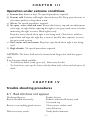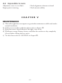
1
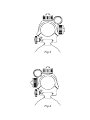
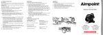
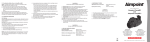
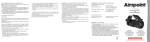
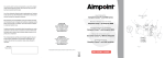
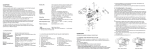
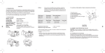
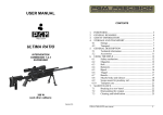
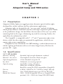
User’s Manual
for
Aimpoint Comp and 7000 series
CHAPTER I
1.1 Presentation
Aimpoint’s Reflex Sights are rugged precision electronic optical red dot sights
developed for civilian, military and law enforcement applications.
Aimpoint sights are designed for the ”two eyes open” method of sighting,
which greatly enhances situational awareness and target acquisition speed. Thanks
to the parallax-free design, the dot follows the movement of the user’s eye while
remaining fixed on the target, eliminating any need for centering. Further, the
sight allows for unlimited eye-relief.
The CompM2 is compatible with 1st , 2nd and 3rd generation night vision
devices, while the other sights are optimized for applications, which do not
require night vision compatibility.
Aimpoint has now introduced the CETechnology, a radical advancement in
red dot sighting performance with over 30 times longer battery life than the
previous XD – sights.
1.2 Specification
1.2.1 All models
Material – housing:
Material – lens covers:
Optical magnification:
Eye relief:
Optical coating:
Dot size:
Battery:
Battery life* (hours):
Extruded, high strength aluminum, anodized
Thermoplastic elastomer, black, non-glare
1X for all models except for 2X
Unlimited, no centering required
Anti Reflex coating, all surfaces
Multi-layer coating for reflection
Band Pass coating for NVD compatibility (CompM2)
4 MOA, 2 MOA for 2X, 7 MOA in CompC SM only
One 3 Volt Lithium battery type 2L76 or DL1/3N
1000 – 10.000 h (typically 10 years at CompM2 NVD
position), 100 – 1000 h for CompC SM (XD Diode)
–2–
Adjustment:
Range ±2 m at 100 meters, in windage and elevation
1 click = 10 mm at 80 meters = 13 mm at 100 meters =
= 1/2" at 100 yards.
*) Average values, depending on brightness setting
MOA: Minute Of Angle 1MOA = 30 mm at 100 meters = 1" at 100 yards
NVD: Night Vision Device
1.2.2 Model 7000SC, 7000L, 7000SC-2X and 7000L-2X
Length:
Width / height
Weight:
Surface finish:
Mounting:
Distance between rings:
Switch, dot brightness:
Max temperature range:
Water resistance:
7000SC: 160 mm (6.3")
7000SC-2X: 195 mm (7.7")
7000L: 200 mm (7.9")
7000L-2X: 235 mm (9.3")
7000SC/L: 55 mm (2.2") 7000SC/L-2X: 60 mm (2.4")
7000SC: 200 gram (7.0 oz) 7000SC-2X: 290 gram (10.2 oz)
7000L: 225 gram (7.9 oz) 7000L-2X: 315 gram (11.1 oz)
Carbon Black or Silver Metalic/SM (only 7000SC), semi-matte
2 rings, 30 mm diameter
7000SC: min 50 mm (2.0"), max 115 mm (4.5")
7000L: min 60 mm (2.4"), max 155 mm (6.1")
10 pos.: 1 Off, 9 daylight of which 1 Extra Bright
-30°C to +60°C (-20°F to +140°F)
Waterproof to 2 m (7 ft) water depth
1.2.3 Model CompC and CompC-2X
Length:
Width / height:
Weight:
Surface finish:
Mounting:
Switch, dot brightness:
Max temperature range:
Water resistance:
CompC: 120 mm (4.7")
CompC-2X: 155 mm (6.1")
CompC: 55 mm (2.2")
CompC-2X: 60 mm (2.4")
CompC: 185 gram (6.5 oz) CompC-2X: 275 gram (9.7 oz)
Carbon Black or Silver Metallic/SM (only CompC), semi-matte
One wide ring, 30 mm diameter
10 pos.: 1 Off, 9 daylight of which 1 Extra Bright
-30°C to +60°C (-20°F to +140°F)
Waterproof to 2 m (7 ft) water depth
1.2.4 Model CompM2, CompML2, CompM2-2X and CompML2-2X
Length (incl. lens covers): CompM2 / ML2: 130 mm (5.1")
CompM2-2X / ML2-2X: 165 mm (6.5")
Width / height:
CompM2 / ML2: 55 mm (2.2")
CompM2-2X / ML2-2X: 60 mm (2.4")
Weight (incl. lens covers): CompM2 / ML2: 200 gram (7.1 oz)
CompM2-2X / ML2-2X: 290 gram (10.2 oz)
–3–
Surface finish:
Mounting:
Switch, dot brightness:
Max temperature range:
Water resistance:
Hard Anodized, Graphite Grey, matte
One wide ring, 30 mm diam, or Aimpoint QR Ring
CompM2 / M2-2X: 10 positions:
4 NVD, 6 daylight of which 1 Extra Bright
CompML2 / ML2-2X: 10 positions:
1 Off, 9 daylight of which 1 Extra Bright
-45°C to +70°C (-50°F to +160°F)
Submersible to 25 m (80 ft) water depth*
*) Tests performed have shown that sights will stand over 100 meters (330 ft) of water depth.
1.3 Location and description of major
components and functions
See fig. 1 and 2
1. Battery Lid
2. Battery
(DL1/3N or similar)
3. Cover for adjustment screw
4. Adjustment Screw
(windage/elevation)
5. Rotary Switch
6. Rubber Strap
(for 7000 models and CompC)
7.
Rubber Strap
(for CompM2 and ML2 models)
8. Eye Protection
9. Lens Cover, rear
(for CompM2 and ML2 models)
10. Lens Cover, front
(for CompM2 and ML2 models)
11. Lens Cover for 2X
(for CompM2 and ML2 models)
CHAPTER II
OPERATION UNDER NORMAL CONDITIONS
2.1. Assembly and preparation for use
WARNING: Insure the weapon is unloaded and the safety selector is in the ”safe”
position before attempting to install, remove or perform maintenance on the sight.
2.1.1. Installing Battery
a) Remove battery cap by turning it counterclockwise.
b) Insert battery with positive (+) end toward cap.
–4–
Caution while replacing battery (not necessary when the sight is unused)
Before installing battery cap, inspect that the O-ring is present and not damaged.
Failure to do so could result in water leakage into the battery compartment.
c) Install battery cap by turning clockwise until snug. Hand tighten only. Using
tools could damage equipment.
d) Verify that red dot is present by turning the rotary switch clockwise.
2.1.2. Installing Ring and Sight on the weapon
Aimpoint’s sights are designed for installation on most types of weapons. For
mounting, certain models come with one or two rings, for other models use standard rings available on the market. If your weapon does not have or support an
appropriate base(s), please consult your dealer, gunsmith or other qualified source.
a) When using two separate bases on the weapon, ensure that the bases are
parallel and aligned.
b) Assemble the ring(s) on the appropriate weapon base (a Weaver or Picatinny
base). When using 2 rings, make sure that the distance between the rings is
appropriate to the sight.
Note: make sure that you have space between the bottom front part of the
sight and the top of the base/weapon.
c´) For Comp models: Assemble the sight to the weapon by using Aimpoint´s
wide 30 mm ring or QR-mount. If other standard 30 mm
rings are used, make sure that the ring(s) covers a length
of minimum 25 mm or 1" (two standard rings could possibly be used).
c") For 7000 models: Assemble the sight to the weapon with any standard 30
mm rings.
d) Ensure that the sight is correctly positioned for right or left hand shooting, see
fig 3 and 4.
e) When using lens covers, ensure that they are correctly positioned and can be
opened.
f ) Finally, make sure that all screws are firmly tightened around the sight.
g) Complete the zeroing (2.2.1).
–5–
2.2. OPERATING PROCEDURES
2.2.1. Zeroing
Aimpoint’s sights are delivered in a centered position. Normally this means that
only small adjustments are necessary, providing that the base(s) are properly aligned.
CAUTION: Do not continue to adjust windage and elevation mechanisms if you
encounter resistance.
The elevation adjustment screw is located on top of the sight, while the windage
screw is located on the right or left side, depending on how the sight has been
mounted on the weapon. (Aimpoint sights can be installed to support either right
hand (fig 3) or left hand (fig 4) shooters.)
a) Open front and rear lens covers.
b) Turn the rotary switch clockwise until the red dot has a sufficient intensity to
contrast against the target.
c) Remove the windage and elevation adjustment caps.
NOTE: Each click of the adjustment screw corresponds to a 10 mm movement of
the point of impact at 80 meters, (3 mm at 25 meters, 13 mm at 100 meters and
25 mm at 200 meters or 1/4" at 50 yds, 1/2" at 100 yds and 1" at 200 yds).
d) Insert adjustment tool (coin, screwdriver, knife) or cartridge casing in adjustment screw slot and turn as follows:
• To move the point of impact to the right, turn windage adjustment screw
counterclockwise (clockwise if screw located on left side).
• To move the point of impact to the left, turn windage adjustment screw
clockwise (counterclockwise if screw located on left side).
• To move the point of impact up, turn elevation adjustment screw counterclockwise.
• To move the point of impact down, turn elevation adjustment screw clockwise.
e) Confirm zeroing by firing at least three shots at a zeroing target. Check impact
points on zeroing target to confirm accuracy and repeat above procedure if required.
f ) After initial firing, ensure that the mount and sight are secure.
g) Turn rotary switch to OFF position (counterclockwise).
h) Close front and rear lens covers.
–6–
CHAPTER III
Operation under extreme conditions
a) Extreme heat (moist or dry). No special procedures required.
b) Extreme cold. Extreme cold might shorten battery life. Keep spare batteries in
your inner pockets to keep them warm.
c) Salt air. No special procedures required.
d) Sea spray, water, mud and snow. Ensure that battery cap and two adjustment
screw caps are tight before exposing the sight to sea spray, mud, snow or before
immersing the sight in water. Hand tighten only.
Keep lens covers closed when sight is not being used. Clean lenses with lens
paper/cloth and wipe the sight dry as soon as possible after exposure to water,
sea spray, mud or snow.
e) Dust storms and sand storms. Keep lens caps closed when sight is not being
used.
f ) High altitudes. No special procedures required.
CAUTION: The lenses shall never be cleaned with fingers but with lens paper/
cloth.
If no lens paper/cloth available :
– To clear away debris (sand, grass etc): blow away the dirt.
– To clean lenses: mist up the lenses and dry them with a clean and soft piece of
cloth.
CHAPTER IV
Trouble shooting procedures
4.1 Red dot does not appear
Discharged battery:
Battery installed incorrectly:
Battery is not making good contact:
Defective rotary switch:
Replace battery
Remove and reinstall battery with
(+) toward cap
Clean contact surfaces and
reinstall battery.
Notify dealer/armourer
–7–
4.2 Impossible to zero
Adjustment screw is at its limit:
Impact point is moving:
Check alignment of mount to barrel
Check mount stability
CHAPTER V
MAINTENANCE
a) This reflex sight does not require any particular maintenance while used under
normal conditions.
b) Under severe weather conditions please refer to chapter III.
c) Keep lens covers closed whenever the sight is not in use.
d) Warehouse storage: Remove battery and allow lens surfaces to dry completely
(if wet) before closing the lens covers.
e) To clean lenses refer to CAUTION in chapter III.
–8–
Fig 1
Fig 2
Fig 3
Fig 4