1
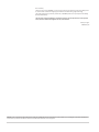
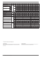
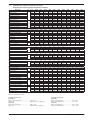
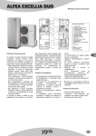
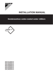
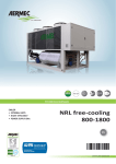
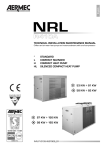
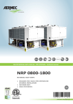
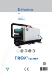
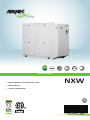
Technical Manual
• WATER COOLED CHILLER AND HEAT PUMP
• INDOOR UNITS
NXW
• SCROLL COMPRESSORS
EN
INXWPY. 14.02. 4438856_01
Dear customer,
Thank you for choosing AERMEC. It is the fruit of many years of experience and special design studies and has been made of the highest grade materials and with cutting edge technology.
The quality level is being constantly monitored, so AERMEC products are synonymous with Safety,
Quality and Reliability.
The data may undergo modifications considered necessary for the improvement of the product,
at any time and without the obligation for any notice thereof.
Thank you again.
AERMEC S.p.A
AERMEC S.p.A. reserves the right at all times to make any modification for the improvement of its product and is not obliged to add these modification
to machines of previous manufacture that have already been delivered or are being built.
SUMMARY
1.
General Warnings.................................................................... 4
1.1.
Storage Of The Documentation............................................... 4
1.2.
Safety Precautions And Installation ........................................ 4
2.
Product Identification.............................................................. 4
3.
Description And Choice Of The Unit........................................ 5
3.1.
Available Models.................................................................... 5
3.2.
Available Versions................................................................... 5
3.3.
Available Versions.................................................................... 5
3.4.
Description And Choice Of The Unit........................................ 6
4.
Description Of Components.................................................... 7
4.1.
Cooling Circuit......................................................................... 7
4.2.
Frame...................................................................................... 7
4.3.
Hydraulic Components............................................................ 7
4.4.
Electrical Components............................................................. 7
4.5.
Electronic Regulation............................................................... 7
5.Accessories.............................................................................. 9
5.1.
Electric Regulation Accessories............................................... 9
5.2.
General Accessories................................................................ 9
6.
Technical Data ....................................................................... 10
6.1.
Version - L (Silenced)............................................................. 10
6.2.
Version H (Heat Pump With Water Side Inversion) .............. 13
Version Hl (Heat Pump With Water Side Inversion.................... - Silenced)............................................................................. 13
7.
Operating Limits.................................................................... 16
7.1.
Operating Limits Standard Version........................................ 16
7.2.
Operating Limit Version E (Condenserless)........................... 16
8.
Corrective Factor.................................................................. 17
8.1.
Heating Capacity And Input Power........................................ 17
8.2.For ∆T Different From The Rated Value................................. 17
8.3.
Fouling Factors....................................................................... 17
8.4.
Cooling Capacity And Input Power........................................ 18
8.5.For ∆T Different From The Rated Value................................. 18
8.6.
Fouling Factors....................................................................... 18
8.7.
Heating Capacity With Desuperheater.................................. 19
8.8.For ∆T Different From The Rated Value................................. 19
8.9.
Fouling Factors....................................................................... 19
8.10. Desuperheater Pressure Drops.............................................. 19
8.11. Heating Capacity With Total Recovery................................... 20
8.12.For ∆T Different From The Rated Value................................. 20
8.13. Fouling Factors....................................................................... 20
8.14. Pressure Drops Total Recovery.............................................. 21
9.
Total Pressure Drops ............................................................. 22
9.1.
Evaporator In Cooling Operation........................................... 22
9.2.
Condenser In Cooling Operation........................................... 23
10.
Useful Heads.......................................................................... 24
11.
Minimum/Maximum Water Content In The System............. 27
12.
Expansion Tank Calibration.................................................... 27
13.
Sound Data............................................................................ 29
13.1. Sound Levels.......................................................................... 29
14.
Safety And Check Parameter Setting..................................... 30
15.
Capacity Control.................................................................... 31
1.
Standards and directives to be
followed in the design and manufacture of the unit:
STANDARD
1. UL 1995 Heating and
cooling equipment
2. ANSI/NFPA Standard 70 National
Electrical code (N.E.C.)
3. CSA C.22.1.- C.22.2 Safety Standard
Electrical Installation
SAFETY LEVEL
1. IP24
NXW AERMEC is built according to recognised
technical standards and safety regulations.
They have been designed for air conditioning
and hot water production and must be used
for this purpose in accordance with their performance characteristics. The company shall
not be contractually or non-contractually liable
for any damage to people, animals or objects,
for failures caused by errors during installation, adjustment and maintenance or incorrect
use. All the uses not expressly indicated in this
manual are not allowed.
1.1.
ACOUSTIC PART
1. ISO DIS 9614/2 (sound intensity method)
REFRIGERANT GAS (R410A)
This unit contains fluorinated
greenhouse gases covered by the
Kyoto Protocol. Maintenance and
disposal operations must be only
carried out by qualified staff, in
compliance with existing laws.
GENERAL WARNINGS
STORAGE OF THE
DOCUMENTATION
Deliver the following instructions plus all the
complementary documentation to the system
user, who shall be responsible for keeping the
instructions so that they are always available
when needed.
Read carefully this chapter; all the procedures
must be carried out by qualified personnel
according to the regulations in force in the different countries (M.D. 329/2004).
The unit must be installed in such a way as to
make all maintenance and/or repair operations
possible.
The warranty of the device does not in any
case cover costs owing to ladder trucks, lifts or
other lifting systems that may be required in
order to carry out repairs under warranty.
Do not modify or tamper with the chiller as
this may cause dangerous situations and the
manufacturer shall not be liable for any damages. The warranty shall not be valid if the
indications mentioned above are not observed.
1.2.
SAFETY PRECAUTIONS
AND INSTALLATION
− the chiller must be installed by an authorised and qualified technician, in compliance with the national legislation in force
TECHNICAL
PLATE
fig.1 technical plate
4
INXWPY. 1402. 4438856_01
in the country of destination
AERMEC shall not be held responsible for
any damage whatsoever resulting from the
non-compliance with these instructions.
− Before starting any work, it is necessary TO
READ CAREFULLY THE INSTRUCTIONS, AND
TO PERFORM THE SAFETY CHECKS TO AVOID
ANY RISKS. All the personnel in charge must
be aware of the operations and the risks
that may arise when all the unit installation
operations begin.
2.
P RODUCT
IDENTIFICATION
NXW are identified by the following:
− PACKAGING LABEL
that includes the product identification
data
− TECHNICAL PLATE
Placed on the right strut side
(see fig.1)
NB
If the identification plate, or any other means
to identify the product, is tampered with,
removed or missing, installation and maintenance operations are hampered
3.
DESCRIPTION AND
CHOICE OF THE UNIT
The NXW Heat pumps and reversible waterwater FOR INDOOR INSTALLATION have been
designed to completely satisfy any plant and
application needs thanks to a wide range of
models, configurations and accessories.
For years Aermec has been attentive to the
energy efficiency issue, and has now designed
the NXW units with the aim of ensuring high efficiency levels with both full and partial loads.
The NXW unit is commissioned and delivered
completely charged with R410A refrigerant and
oil (on site it will be necessary only to provide
the hydraulic and electric connections), while
the Condenserless <<E>> versions are delivered
only with a watertight charge (data available on
demand).
3.1.
sound-absorbing capacity
Heat recovery units:
− Without recovery units °
− Desuperheater D: They are equipped with a
partial plate heat recovery unit installed in
series with the condenser.
− Total recovery T: They are equipped with a
plate heat exchanger installed in parallel to
the condenser for total recovery of the dissipated heat.
AVAILABLE MODELS
− Heat pump H (heat pump with gas side
cycle inversion)
Extended operating limits:
Condenser:
− Standard °
− Condenserless E (on demand)
− temperature of condenser output water up
to 55°/131°F
− temperature of evaporator output water
down to -8°/18°F
3.3.
3.2.
AVAILABLE VERSIONS
− Silenced L
kit evaporator and hydronic kit condenser,
optimising spaces, times and installation costs.
The following configurator shows the methods
by which the commercial code of 15 fields that
make it up representing the options available is
compiled.
Reduced sound emission thanks to total compressor casing of the machine
with galvanised sheet metal panels
of a suitable thickness and with good
AVAILABLE VERSIONS
NXW range chillers are available in
11 sizes. By combining the wide variety of available options, it is possible to
configure each model in the NXW range in
such a way as to meet the most varied system
requirements. To make installation easier, the
machine can be provided with an hydronic
INXWPY. 1402. 4438856_01 5
3.4.
DESCRIPTION AND CHOICE OF THE UNIT
123
4567
8
9
10
11
12
13
14
15
NXW
0650
°
°
°
°
°
°
°
°
Field:
123
Code
NXW
4567
Size:
0500, 0550, 0600, 0650, 0700, 0750, 0800, 0900, 1000, 1250, 1400
8
9
10
11
12
13
14
15
Field of use:
°
Y
X
Standard mechanical thermostatic valve up to +4°C/39°F
Low water temperature mechanical thermostatic valve
(down to 4°C/39°F up to -8°C/18°F)
Electronic thermostatic valve also for low water temperature (up to -8°C/18°F)
Model:
°
heat pump with water side inversion
H
heat pump with gas side cycle inversion
Version:
L
silenced
Evaporator:
°
E
standard
condenserless (technical data on demand)
Heat recovery
°
D
T
without recovery units
with desuperheater
with total heat recovery
Power supply
6 (1)
7
8
230V~3 60Hz with thermomagnetic switches
460V~3 60Hz with thermomagnetic switches
575V~3 60Hz with thermomagnetic switches
Evaporator side pumps (2)
°
M
N
O
P
without pumping assembly
low-head pump
low-head pump and reserve pump
high-head pump
high-head pump and reserve pump
Condenser side pumps (2)
°
U
V
W
Z
without pumping assembly
low-head pump
low-head pump and reserve pump
high-head pump
high-head pump and reserve pump
– the standard options are shown by the symbol °;
– these combinations are not possible: YD, YT HE, HT, ET, T with evaporator or condenser side pumps
(1)
available only for sizes 0500 to 0800
(2)
“evaporator” is the heat exchanger that works as such in cooling mode; “condenser” is the heat exchanger that works as such in heating mode
6
INXWPY. 1402. 4438856_01
4.
4.1.
DESCRIPTION OF
COMPONENTS
COOLING CIRCUIT
Compressor
Scroll-type hermetic compressors fitted with
electrical carter compressors heating elements
as standard. The heating element is powered
automatically when the unit is still provided
the unit is kept powered up.
Evaporator
Plate type (AISI 316). It is insulated externally
with closed cell material to reduce thermal
dispersions.
Condensers
Plate type (AISI 316). It is insulated externally
with closed cell material to reduce thermal
dispersions.
Filter-drier
Of the mechanical cartridge type, made of
ceramics and hygroscopic material able to trap
impurities and any traces of humidity in the
cooling circuit.
Liquid separator
(for E version only)
Located on the suction point of the compressor, to protect against any flowback of liquid
refrigerant, flooded start-ups, operation in the
presence of liquid
Liquid indicator
One per circuit, for checking the refrigerant gas
load and any humidity in the cooling circuit.
Thermostatic valve
The valve with external equaliser on the output
of the evaporator, modulates the gas flow to
the evaporator in accordance with the heat
load in such a way as to assure a sufficient
degree of overheating at the intake gas.
Taps
They are located in the liquid and discharge
lines and allow to intercept the refrigerant in
case of extraordinary maintenance.
Solenoid valve
The valve closes when the compressor turns off,
preventing the flow of refrigerant gas towards
the evaporator.
4.2.
F RAME
Load-bearing structure realised in suitably
thick heat galvanized steel sheets, it is painted
with polyester dust to guarantee resistance to
atmospheric agents (RAL 9002)
SOUND PROTECTION COVERING (Only silenced
versions)
It is comprised of panels in suitably thick
galvanized sheet metal and internally finished
with sound-proofing material. Allows the
sound power level emitted from the unit to be
reduced by 6 db(A).
4.3.
HYDRAULIC COMPONENTS
Flow switch (installed on the versions with a
pump).
Its job is to make sure that there is water circulation in the evaporator. If this is not the case,
it shuts down the unit.
NOTE:
In the heat pump vesion, there is a second flow
switch (condenser side)
Circulation pump
(Condenser/Evaporator)
Depending on the characteristics of the pump
chosen, it offers a useful head to overcome the
pressure drops in the system. There is also the
possibility to have a reserve pump.
The reserve pump is managed by the electronic
card.
Water filter
versions standard: NOT INCLUDED
versions with a pumps: INCLUDED
Allows you to block and eliminate any impurities in the hydraulic circuits. Inside, it has a
filtering mesh with holes not greater than one
millimetre. It is indispensable to avoid serious
damage to the plate heat exchanger.
NB The filter protects only the exchangers (in case of particularly dirty water,
we recommend an external filter to
protect the pumps)
Drain valve
(versions with water accumulator or pump)
Of the automatic type, assembled on the upper
part of the hydraulic system; it releases any air
bubbles that may be present in the system.
Expansion tank 6,6gal (standard in the version with
pump)
With nitrogen pre-load membrane. In the version [°]
is positioned on the evaporator, while in the version
[H] is positioned on the heat exchanger that
works as evaporator in cooling mode
SAFETY AND CONTROL COMPONENTS
Low pressure transducer
Allows displaying, on the microprocessor board
display, the value of the compressor's suction
pressure (one per circuit) on the low-pressure
side of the cooling circuit
High pressure transducer
Allows displaying, on the microprocessor board
display, the value of the compressor's delivery
pressure (one per circuit) On the high pressure
side of the cooling circuit
High pressure switch
Factory-calibrated, it is placed on the high pressure side of the cooling circuit, it shuts down
compressor operation in the case of abnormal
operating pressure.
Cooling circuit safety valves (HP)
Calibrated at 653psi HP, they cut in relieving
the overpressure in the case of abnormal
operating pressures.
Thermomagnetic switches to protect the
compressors.
4.4.
E LECTRICAL COMPONENTS
Electrical panel
Contains the power section and the management of the controls and safety devices.
Door-block disconnecting switch
It is possible to access the electrical panel by
disconnecting the voltage, then using the opening lever of the panel itself. This lever can be
blocked with one or more padlocks during maintenance, in order to prevent the machine being
powered up accidentally.
Control keypad
Provides full control functions.
NB
For a more detailed description refer to
the user manual.
4.5.
ELECTRONIC REGULATION
Electronic regulation on the NXW chillers
consists of a control board and a control panel
with display. On each board transducers, loads
and alarms are connected. The programme
and parameter presets are stored permanently
in the controller’s FLASH memory, to ensure
that they are kept in memory even when the
system is not powered (without the need for an
auxiliary battery).
The connection to the serial supervision
assistance line in accordance with the RS485
standard, is performed through the serial
boards ACCESSORY RS485P1 and the communication protocol.
• The terminal, which is always controlled by
microprocessor, is equipped with a display,
a keypad and a set of LEDs, and is used for
programming check parameters (Set Points,
differential band, alarm threshold) and for
fundamental user operations (ON/OFF, display
of controlled values).
The terminal does not need to be connected to
the PGD1 for normal controller operation, and
is necessary only when initially programming
the basic parameters.
Microprocessor
− Multilingual menu
− Phase sequence control
− Independent control of individual compressors
− Ammetric transformer
− Cumulative failure block signalling
− Alarm log function
− Daily/weekly programming
− Inlet/outlet water temperature display
− Alarm display
− Full proportional regulation of the output
water temperature
INXWPY. 1402. 4438856_01 7
− Programmable timer function
− Interfaceability with the Modbus protocol
(accessory)
− Control and management of pump/s rotation
− Compressor rotation control
− Analogue input from 4 to 20 mA
− “Always Working” function. In case of
critical conditions the machine does not
arrest but is able to self-adjust itself and
provide maximum output power in those
conditions
− Self adapting operating differential
“Switching Histeresys” to ensure correct
compressor operation at all times even
in plants with a low water content or insufficient flow rates. This system reduces the
compressor wear
− The PDC “Pull Down Control” system to
prevent the activation of the power steps
when the water temperature is approaching the set point quickly. It optimises the
operation of the machine both when
running normally or when there are load
variations, thereby assuring top machine
efficiency in all situations.
For further information, refer to the user
manual.
Example of NXW version [°]
1
3
4
2
6
5
HYDRAULIC CIRCUIT KEY
1 Condenser
2 Evaporator (plate-type exchangers)
3 Flow switch
4Filter
5Pump
6 Expansion tank
NB
The Victaulic joints and the soldering
studs for the condenser and evaporator
are provided
8
INXWPY. 1402. 4438856_01
5.
ACCESSORIES
5.1.
ELECTRIC REGULATION
ACCESSORIES
pressor No. 1 .
PGD1: In addition to the control terminal
on board the machine itself, NXW machines can also be equiped with an external
PGD1 remote control terminal. PGD1
remote terminals provide the same functions as the on-board terminals (keyboard
controls and display).
− PGD1 terminals can be installed at distances of up to 1 km from the machine (up
to 164ft with telephone cable AWG24, for
distances of over 50 metres ensure that the
2nd extension card is powered by a voltage
between 21 and 30 V dc.
−
− AER485P1: Through this accessory, it is possible
to connect the unit with BMS supervision
systems with electrical standard RS 485 and
MODBUS type protocol
NOTE: disclosure must be provided for com-
5.2.
G ENERAL ACCESSORIES
−AVX: spring anti-vibration supports
ELECTRONIC REGULATION DIAGRAM
pCO3 MASTER
RS485
Modbus
RS485P2
CIRCUITO11
CIRCUIT
pCO3 MASTER
CIRCUITO22
CIRCUIT
PGD1
BOARD
AER485P1
COMPATIBILITY OF ACCESSORIES
NXW
AER485P1
ALL
PGD1
AVX
0500
0550
0600
0650
0700
0750
0800
0900
1000
1250
1400
Through this accessory it is possible to connect the unit with BMS supervision systems with electrical standard RS 485 and
MODBUS type protocol.
•
•
•
•
•
•
•
•
•
•
•
•
•
•
•
REMOTE CONTROL TERMINAL PGD1
•
•
•
•
•
•
•
Spring antivibration support. (for more information about compatibility contact us)
INXWPY. 1402. 4438856_01 9
6.
TECHNICAL DATA
6.1.
VERSION - L (SILENCED)
Mod. NXW
vers
Cooling capacity [1]
Total input power
Evaporator water flow rate
L
Evaporator pressure drop
Condenser water flow rate
Pressure drop at condenser
Heating capacity [2]
Total input power
Condenser water flow rate
L
Pressure drop at condenser
Evaporator water flow rate
Evaporator pressure drop
ENERGY INDEXES
EER
L
COP
L
AHRI PART LOAD RATINGS
IPLV
EER (100% load)
EER (75% load)
L
EER (50% load)
EER (25% load)
ELECTRICAL DATA (230V-3-60Hz power supply)
Input current (cooling)
L
Input current (heating)
No pump version
LRA
MCA
L
MOP
Recommended fuse
Evap + cond low head pumps
LRA
MCA
L
MOP
Recommended fuse
Evap + cond high head pumps
LRA
MCA
L
MOP
Recommended fuse
ELECTRICAL DATA (460V-3-60Hz power supply)
Input current (cooling)
L
Input current (heating)
No pump version
LRA
MCA
L
MOP
Recommended fuse
Evap + cond low head pumps
LRA
MCA
L
MOP
Recommended fuse
Evap + cond high head pumps
LRA
MCA
L
MOP
Recommended fuse
U.M.
ton
kW
gpm
PSI
gpm
PSI
BTU/h
kW
gpm
PSI
gpm
PSI
0500
31,76
23,5
76,16
2,8
95,64
2,6
0550
34,66
25,0
83,10
3,2
104,35
3,0
0600
36,77
27,2
88,13
3,6
110,68
3,5
0650
42,25
30,4
101,29
4,1
127,19
3,5
0700
47,06
35,1
112,80
4,8
141,66
4,2
0750
54,17
38,7
129,81
3,9
163,02
2,6
0800
62,78
47,4
150,49
4,5
188,99
3,3
0900
70,92
55,2
169,99
5,5
213,47
4,2
1000
80,16
61,6
192,10
3,8
241,25
3,2
1250
90,51
69,7
216,96
3,5
272,47
3,6
1400
101,77
77,4
243,92
3,5
306,32
3,8
412600
449500
476800
545400
609600
695400
818300
924500
1047800
1184800
1326500
28,5
91,46
2,3
70,96
2,3
31,1
99,64
2,8
77,28
2,8
33,7
105,72
3,0
81,50
3,0
38,4
120,95
3,2
93,35
3,3
43,8
135,20
3,9
103,67
4,1
47,4
154,20
2,3
120,10
3,3
57,4
181,46
3,2
140,17
3,9
66,3
205,02
3,9
157,32
4,8
73,6
232,37
2,9
179,43
3,3
83,4
262,69
3,3
202,69
3,0
92,8
294,17
3,5
227,41
3,0
BTU/W
W/W
16,23
4,24
16,65
4,23
16,23
4,15
16,69
4,16
16,10
4,07
16,81
4,30
15,90
4,17
15,43
4,08
15,62
4,17
15,59
4,16
15,79
4,19
W/W
W/W
W/W
W/W
W/W
6,11
4,76
5,56
6,49
6,75
6,27
4,88
5,70
6,65
6,93
6,24
4,75
5,68
6,62
6,90
6,27
4,88
5,71
6,66
6,94
6,06
4,72
5,51
6,43
6,70
6,33
4,92
5,75
6,72
6,99
5,99
4,66
5,44
6,35
6,62
5,81
4,52
5,28
6,16
6,42
5,88
4,58
5,35
6,24
6,50
5,87
4,57
5,34
6,23
6,49
5,94
4,62
5,40
6,31
6,57
A
A
93
106
89
105
100
116
106
125
126
149
144
168
188
213
-
-
-
-
A
A
A
A
402
140
202
200
374
146
203
200
414
152
214
200
350
158
195
175
431
203
260
250
471
243
300
300
526
264
326
300
-
-
-
-
A
A
A
A
418
155
218
200
390
161
218
200
430
168
230
225
368
176
213
200
451
223
280
250
495
266
323
300
553
291
353
350
-
-
-
-
A
A
A
A
422
160
222
200
394
166
223
200
434
172
234
225
374
181
218
200
458
229
286
250
507
278
335
300
562
299
361
350
-
-
-
-
A
A
42
48
43
50
48
55
53
62
60
70
65
76
85
97
90
104
94
109
107
123
119
137
A
A
A
A
210
68
97
90
192
73
98
90
221
79
108
100
187
87
107
100
217
98
123
110
227
108
133
125
270
128
157
150
321
138
172
150
331
149
183
175
391
177
224
200
417
203
250
225
A
A
A
A
218
76
105
100
200
81
106
100
229
87
116
110
196
96
116
110
227
108
133
125
239
120
145
125
284
141
170
150
337
154
188
175
347
164
198
175
409
195
242
225
434
221
267
250
A
A
A
A
220
78
107
100
202
83
108
100
231
89
118
110
199
99
119
110
230
112
137
125
245
126
151
150
288
146
175
150
343
160
194
175
359
177
211
200
419
206
252
250
445
231
278
250
Reference data (AHRI standard):
In cooling operation [1]:
Evaporator:
Water outlet temperature.............................6,7°C - 44°F
Water flow..................................................... 0,043l/s per kW - 2,4gpm/ton
Condenser:
Water inlet temperature...............................29,4°C - 85°F
Water flow..................................................... 0,054l/s per kW - 3gmp/ton
10
INXWPY. 1402. 4438856_01
In heating operation [2]:
Evaporator:
Water inlet temperature...............................10°C - 50°F
Water outlet temperature.............................5°C - 41°F
Condenser:
Water inlet temperature...............................40°C - 104°F
Water outlet temperature.............................45°C - 113°F
Mod. NXW
vers
ELECTRICAL DATA (575V-3-60Hz power supply)
Input current (cooling)
L
Input current (heating)
No pump version
LRA
MCA
L
MOP
Recommended fuse
Evap + cond low head pumps
LRA
MCA
L
MOP
Recommended fuse
Evap + cond high head pumps
LRA
MCA
L
MOP
Recommended fuse
CHARGE (Circuit C1/C2)
U.M.
0500
0550
0600
0650
0700
0750
0800
0900
1000
1250
1400
A
A
33
37
33
39
37
43
41
48
46
54
50
58
65
74
70
80
73
84
82
95
91
105
A
A
A
A
160
61
88
80
139
58
80
80
162
63
90
80
125
62
77
75
161
80
102
100
177
96
118
110
214
115
142
125
263
117
145
125
266
120
148
125
335
145
184
175
358
168
207
200
A
A
A
A
166
67
94
90
146
64
86
80
169
70
96
90
132
70
84
80
169
88
110
110
186
105
127
125
225
126
152
150
276
130
157
150
278
133
160
150
349
160
198
175
372
182
221
200
A
A
A
A
168
69
96
90
147
66
88
80
170
71
98
90
134
72
86
80
172
91
113
110
191
110
132
125
228
129
156
150
281
135
162
150
288
143
170
150
358
168
207
200
380
191
229
200
lb (C1)
lb (C2)
gal (C1)
gal (C2)
16,1
16,1
0,9
0,9
16,1
16,1
1,8
0,9
16,1
16,1
1,8
0,9
19,2
19,2
1,8
1,8
19,2
19,2
1,8
1,8
28,7
28,7
1,8
1,8
29,1
29,1
1,8
1,8
29,1
29,1
2,5
1,8
43,2
43,2
2,5
2,5
48,5
48,5
3,0
3,0
59,1
59,1
3,6
3,6
L
n° / n°
2/2
3/2
3/2
4/2
4/2
4/2
4/2
4/2
4/2
4/2
4/2
L
n° / n°
gal
inch
1
2,5
2" 1/2
1
2,5
2" 1/2
1
2,5
2" 1/2
1
2,8
2" 1/2
1
2,8
2" 1/2
1
3,9
2" 1/2
1
4,4
2" 1/2
1
4,4
2" 1/2
1
8,0
3"
1
9,9
3"
1
12,0
3"
L
n° / n°
gal
inch
1
3,2
2" 1/2
1
3,2
2" 1/2
1
3,2
2" 1/2
1
3,9
2" 1/2
1
3,9
2" 1/2
1
8,0
2" 1/2
1
8,0
2" 1/2
1
8,0
2" 1/2
1
12,0
3"
1
13,2
3"
1
16,1
3"
426900
464500
495200
563500
631800
720600
850400
959700
1079200
1226100
1376400
L
BTU/h
n° / n°
kW
gpm
PSI
inch
1
28,9
94,95
2,5
2" 1/2
1
31,4
102,80
2,9
2" 1/2
1
34,1
109,57
3,3
2" 1/2
1
38,8
125,31
3,3
2" 1/2
1
44,3
140,06
4,1
2" 1/2
1
48,0
160,16
2,5
2" 1/2
1
58,2
188,44
3,3
2" 1/2
1
67,3
213,02
4,2
2" 1/2
1
74,4
239,64
3,0
3"
1
84,5
271,63
3,5
3"
1
94,0
305,51
3,6
3"
L
BTU/h
n° / n°
gpm
PSI
lb
inch
74500
2
16,51
0,1
50,7
1" 1/2
80600
2
17,87
0,2
50,7
1" 1/2
86100
2
19,08
0,2
50,7
1" 1/2
97000
2
21,51
0,2
50,7
1" 1/2
107900 116100
2
2
23,93
25,75
0,2
0,3
50,7
50,7
1" 1/2 1" 1/2
138000
2
30,60
0,3
50,7
1" 1/2
161500 170800 190600 210400
2
2
2
2
35,82
37,86
42,26
46,65
0,4
0,3
0,4
0,5
63,9
63,9
63,9
63,9
1" 1/2 1" 1/2 1" 1/2 1" 1/2
2,2
3,0
7,8
3,9
3,1
10,0
5,0
4,0
3,6
5,3
2,2
3,0
7,8
3,9
3,1
10,0
5,0
4,0
3,4
5,1
2,2
3,0
7,8
3,9
3,1
10,0
5,0
4,0
3,2
5,0
2,2
3,0
7,8
3,9
3,1
10,0
5,0
4,0
2,9
4,6
Refrigerant R410A
L
Oil
L
COMPRESSOR
Quantity / Circuit
EVAPORATOR
Quantity
Water content
Water connections (Victaulic)
CONDENSER
Quantity
Water content
Water connections (Victaulic)
TOTAL HEAT RECOVERY
Recovered heating capacity [3]
Quantity
Chiller input power
Total recovery water flow
Total recovery pressure drop
Water connections (Victaulic)
DESUPERHEATER
Recovered heating capacity [3]
Quantity
Desuperheater water flow
Desuperheater pressure drop
Weight
Water connections (Victaulic)
EVAPORATOR PUMPS
Input power (L.P. - M, N)
Input power (H.P. - O, P)
Input current (M, N)
Input current (O, P)
kW
~230V
~460V
~575V
~230V
~460V
~575V
A
L
Available head (L.P. - M, N) (*)
Available head (H.P. - O, P) (*)
(*)
A
PSI
3,0
4,0
10,0
5,0
4,0
13,2
6,6
5,3
2,7
5,5
3,0
4,0
10,0
5,0
4,0
13,2
6,6
5,3
2,5
5,0
4,0
4,0
13,2
6,6
5,3
13,2
6,6
5,3
3,1
4,1
4,0
7,5
6,6
5,3
11,0
8,8
2,5
5,4
4,0
7,5
6,6
5,3
11,0
8,8
3,1
5,9
4,0
7,5
6,6
5,3
11,0
8,8
2,6
5,4
4,0
7,5
6,6
5,3
11,0
8,8
2,0
4,7
Performance values refer to cooling mode
Cooling with recovery operation [3]:
Evaporator:
Water outlet temperature.............................6,7°C - 44°F
Water flow..................................................... 0,043l/s per kW - 2,4gpm/ton
Desuperheater / Total recovery:
Water inlet temperature...............................40°C - 104°F
Water outlet temperature.............................45°C - 113°F
INXWPY. 1402. 4438856_01 11
Mod. NXW
CONDENSER PUMPS
Input power (L.P. - U, V)
Input power (H.P. - W, Z)
Input current (U, V)
Input current (W, Z)
vers
U.M.
kW
~230V
~460V
~575V
~230V
~460V
~575V
Available head (L.P. - U, V) (*)
Available head (H.P. - W, Z) (*)
EXPANSION VESSEL
Quantity / Capacity
Expansion vessel calibration
SOUND DATA
Sound power
Sound pressure
DIMENSIONS (without pumps)
A
L
A
PSI
0500
0550
0600
0650
0700
0750
0800
0900
1000
1250
1400
2,2
3,0
7,8
3,9
3,1
10,0
5,0
4,0
22,0
33,8
2,2
3,0
7,8
3,9
3,1
10,0
5,0
4,0
20,0
31,8
2,2
3,0
7,8
3,9
3,1
10,0
5,0
4,0
18,4
30,2
3,0
4,0
10,0
5,0
4,0
13,2
6,6
5,3
18,0
35,5
3,0
4,0
10,0
5,0
4,0
13,2
6,6
5,3
15,4
30,9
4,0
7,5
13,2
6,6
5,3
22,0
11,0
8,8
21,0
41,2
4,0
7,5
13,2
6,6
5,3
22,0
11,0
8,8
15,7
35,2
5,5
7,5
9,2
7,4
11,0
8,8
18,4
28,7
5,5
11,0
9,2
7,4
17,3
13,8
21,8
38,0
7,5
11,0
11,0
8,8
17,3
13,8
25,2
33,6
7,5
11,0
11,0
8,8
17,3
13,8
16,8
28,6
L
n° / gal
PSI
1 / 6,6
21,8
1 / 6,6
21,8
1 / 6,6
21,8
1 / 6,6
21,8
1 / 6,6
21,8
1 / 6,6
21,8
1 / 6,6
21,8
1 / 6,6
21,8
1 / 6,6
21,8
1 / 6,6
21,8
1 / 6,6
21,8
L
dB(A)
dB(A)
79
47
78
46
79
47
79
47
80
48
80
48
82
50
85
53
87
55
89
57
90
58
L
mm
in
mm
in
mm
in
kg
lb
Hight
Width
Length
Weight
1885
74,2
730
1609,4
791
1743,9
792
1746,1
800
31,5
2090
82.28
878
1935,7
887
1955,5
1030
2270,8
1073
2365,6
1265
2788,8
1885
74,2
800
31,5
2420
95,28
1569
1676
3459,1 3694,9
1826
4025,6
DIMENSIONS (with 4 pumps)
Hight
Width
L
Length
Weight
(*)
mm
in
mm
in
mm
in
kg
lb
1120
2469,2
1180
2601,5
1885
74,2
74,2
800
31,5
2944
115.90
1294
2852,8
800
31,5
3412
134.33
2250
2357
4960,4 5196,3
1329
2929,9
1549
3415,0
1566
3452,4
1873
4129,3
2507
5527,0
Performance values refer to cooling mode
SOUND POWER
Aermec determines sound power values on the basis of measurements
made in accordance with UNI EN ISO 9614-2, as required for Eurovent
certification.
12
1181
2603,7
1885
INXWPY. 1402. 4438856_01
SOUND PRESSURE
Sound pressure in free field, at 10 m / 32,8ft distance from the external surface of the unit (in accordance with UNI EN ISO 3744)
6.2.
VERSION H (HEAT PUMP WITH WATER SIDE INVERSION)
VERSION HL (HEAT PUMP WITH WATER SIDE INVERSION - SILENCED)
Mod. NXW
vers
Cooling capacity [1]
Total input power
Evaporator water flow rate
L
Evaporator pressure drop
Condenser water flow rate
Pressure drop at condenser
Heating capacity [2]
Total input power
Condenser water flow rate
L
Pressure drop at condenser
Evaporator water flow rate
Evaporator pressure drop
ENERGY INDEXES
EER
L
COP
L
AHRI PART LOAD RATINGS
IPLV
EER (100% load)
EER (75% load)
L
EER (50% load)
EER (25% load)
ELECTRICAL DATA (230V-3-60Hz power supply)
Input current (cooling)
L
Input current (heating)
No pump version
LRA
MCA
L
MOP
Recommended fuse
Evap + cond low head pumps
LRA
MCA
L
MOP
Recommended fuse
Evap + cond high head pumps
LRA
MCA
L
MOP
Recommended fuse
ELECTRICAL DATA (460V-3-60Hz power supply)
Input current (cooling)
L
Input current (heating)
No pump version
LRA
MCA
L
MOP
Recommended fuse
Evap + cond low head pumps
LRA
MCA
L
MOP
Recommended fuse
Evap + cond high head pumps
LRA
MCA
L
MOP
Recommended fuse
U.M.
ton
kW
gpm
PSI
gpm
PSI
BTU/h
kW
gpm
PSI
gpm
PSI
0500
31,88
23,7
76,42
1,9
95,97
2,6
0550
34,83
25,2
83,49
2,2
104,85
3,0
0600
37,53
27,0
89,97
2,0
112,98
2,8
0650
42,59
30,7
102,07
2,5
128,18
3,5
0700
48,20
35,0
115,55
2,8
145,11
3,9
0750
53,94
38,9
129,29
1,7
162,36
2,6
0800
62,36
47,6
149,44
2,3
187,67
3,3
0900
73,11
54,2
175,22
1,9
220,05
2,6
1000
82,66
62,0
198,12
2,0
248,81
3,0
1250
91,79
70,2
219,98
2,6
276,25
3,8
1400
103,08
78,0
247,06
2,6
310,27
3,8
388700
422800
453900
517800
584400
656100
773900
888000
995600
1121200
1254400
28,6
86,15
2,3
65,58
1,2
31,4
93,75
2,8
71,17
1,5
33,4
100,61
2,5
76,55
1,3
38,8
114,84
3,2
86,95
1,6
43,9
129,55
3,3
98,00
1,7
47,8
145,48
2,3
111,09
1,2
57,4
171,58
3,2
130,28
1,6
64,9
196,89
2,3
150,20
1,3
73,2
220,75
2,6
168,08
1,5
83,6
248,59
3,2
188,44
1,7
93,2
278,17
3,3
211,12
1,7
BTU/W
W/W
16,15
3,98
16,60
3,95
16,69
3,97
16,66
3,91
16,54
3,90
16,65
4,02
15,73
3,95
16,20
4,01
16,01
3,98
15,70
3,93
15,87
3,94
W/W
W/W
W/W
W/W
W/W
6,08
4,73
5,53
6,45
6,72
6,26
4,87
5,69
6,64
6,92
6,29
4,89
5,72
6,67
6,95
6,27
4,88
5,70
6,66
6,93
6,22
4,84
5,65
6,60
6,87
6,26
4,87
5,70
6,65
6,92
5,92
4,61
5,38
6,28
6,54
6,10
4,74
5,54
6,47
6,74
6,03
4,69
5,48
6,39
6,66
5,91
4,60
5,37
6,27
6,53
5,97
4,65
5,43
6,34
6,60
A
A
94
106
90
105
100
116
107
126
126
149
144
168
188
214
-
-
-
-
A
A
A
A
402
140
202
200
374
146
203
200
414
152
214
200
350
158
195
175
431
203
260
250
471
243
300
300
526
264
326
300
-
-
-
-
A
A
A
A
418
155
218
200
390
161
218
200
430
168
230
225
368
176
213
200
451
223
280
250
495
266
323
300
553
291
353
350
-
-
-
-
A
A
A
A
422
160
222
200
394
166
223
200
434
172
234
225
374
181
218
200
458
229
286
250
507
278
335
300
562
299
361
350
-
-
-
-
A
A
42
48
43
51
48
55
53
63
59
70
65
76
85
97
89
102
94
109
60
124
119
137
A
A
A
A
210
68
97
90
192
73
98
90
221
79
108
100
187
87
107
100
217
98
123
110
227
108
133
125
270
128
157
150
321
138
172
150
331
149
183
175
391
177
224
200
417
203
250
225
A
A
A
A
218
76
105
100
200
81
106
100
229
87
116
110
196
96
116
110
227
108
133
125
239
120
145
125
284
141
170
150
337
154
188
175
347
164
198
175
409
195
242
225
434
221
267
250
A
A
A
A
220
78
107
100
202
83
108
100
231
89
118
110
199
99
119
110
230
112
137
125
245
126
151
150
288
146
175
150
343
160
194
175
359
177
211
200
419
206
252
250
445
231
278
250
Reference data (AHRI standard):
In cooling operation [1]:
Evaporator:
Water outlet temperature.............................6,7°C - 44°F
Water flow..................................................... 0,043l/s per kW - 2,4gpm/ton
Condenser:
Water inlet temperature...............................29,4°C - 85°F
Water flow..................................................... 0,054l/s per kW - 3gmp/ton
In heating operation [2]:
Evaporator:
Water inlet temperature...............................10°C - 50°F
Water outlet temperature.............................5°C - 41°F
Condenser:
Water inlet temperature...............................40°C - 104°F
Water outlet temperature.............................45°C - 113°F
INXWPY. 1402. 4438856_01 13
Mod. NXW
vers
U.M.
ELECTRICAL DATA (575V-3-60Hz power supply)
Input current (cooling)
A
H-HL
Input current (heating)
A
No pump version
LRA
A
MCA
A
H-HL
MOP
A
Recommended fuse
A
Evap + cond low head pumps
LRA
A
MCA
A
H-HL
MOP
A
Recommended fuse
A
Evap + cond high head pumps
LRA
A
MCA
A
H-HL
MOP
A
Recommended fuse
A
CHARGE (Circuit C1/C2)
lb (C1)
Refrigerant R410A
H-HL
lb (C2)
gal (C1)
Oil
H-HL
gal (C2)
COMPRESSOR
Quantity / Circuit
H-HL n° / n°
EVAPORATOR
Quantity
n° / n°
Water content
gal
H-HL
Water connections
inch
(Victaulic)
CONDENSER
Quantity
n° / n°
Water content
gal
H-HL
Water connections
inch
(Victaulic)
DESUPERHEATER [3]
Recovered heating
BTU/h
capacity
Quantity
n° / n°
Desuperheater water flow
gpm
Desuperheater pressure
H-HL
PSI
drop
Weight
lb
Water connections
inch
(Victaulic)
EVAPORATOR PUMPS
Input power (L.P. - M, N)
kW
Input power (H.P. - O, P)
~230V
Input current
~460V
A
(M, N)
~575V
~230V
Input current
H-HL
~460V
A
(O, P)
~575V
Available head (L.P. - M,
N) (*)
PSI
Available head (H.P. - O,
P) (*)
(*)
0500
0550
0600
0650
0700
0750
0800
0900
1000
1250
1400
33
37
33
39
37
42
41
48
46
54
50
59
66
75
69
79
73
84
46
95
92
106
160
61
88
80
139
58
80
80
162
63
90
80
125
62
77
75
161
80
102
100
177
96
118
110
214
115
142
125
263
117
145
125
266
120
148
125
335
145
184
175
358
168
207
200
166
67
94
90
146
64
86
80
169
70
96
90
132
70
84
80
169
88
110
110
186
105
127
125
225
126
152
150
276
130
157
150
278
133
160
150
349
160
198
175
372
182
221
200
168
69
96
90
147
66
88
80
170
71
98
90
134
72
86
80
172
91
113
110
191
110
132
125
228
129
156
150
281
135
162
150
288
143
170
150
358
168
207
200
380
191
229
200
17,0
17,0
0,9
0,9
17,0
17,0
1,8
0,9
20,5
20,5
1,8
0,9
20,5
20,5
1,8
1,8
23,1
23,1
1,8
1,8
30,9
30,9
1,8
1,8
30,9
30,9
1,8
1,8
46,7
46,7
2,5
1,8
51,4
51,4
2,5
2,5
51,4
51,4
3,0
3,0
62,4
62,4
3,6
3,6
2/2
3/2
3/2
4/2
4/2
4/2
4/2
4/2
4/2
4/2
4/2
1
3,2
1
3,2
1
3,9
1
3,9
1
4,4
1
8,0
1
8,0
1
12,0
1
13,2
1
13,2
1
16,1
2" 1/2
2" 1/2
2" 1/2
2" 1/2
2" 1/2
2" 1/2
2" 1/2
2" 1/2
3"
3"
3"
1
3,2
1
3,2
1
3,9
1
3,9
1
4,4
1
8,0
1
8,0
1
12,0
1
13,2
1
13,2
1
16,1
2" 1/2
2" 1/2
2" 1/2
2" 1/2
2" 1/2
2" 1/2
2" 1/2
2" 1/2
3"
3"
3"
74500
80600
86100
97000
107900
116100
138000
161500
170800
190600
210400
2
16,5
2
17,9
2
19,1
2
21,5
2
23,9
2
25,7
2
30,6
2
35,8
2
37,9
2
42,3
2
46,6
0,1
0,2
0,2
0,2
0,2
0,3
0,3
0,4
0,3
0,4
0,5
50,7
50,7
50,7
50,7
50,7
50,7
50,7
63,9
63,9
63,9
63,9
1" 1/2
1" 1/2
1" 1/2
1" 1/2
1" 1/2
1" 1/2
1" 1/2
1" 1/2
1" 1/2
1" 1/2
1" 1/2
2,2
3,0
7,8
3,9
3,1
10,0
5,0
4,0
2,2
3,0
7,8
3,9
3,1
10,0
5,0
4,0
2,2
3,0
7,8
3,9
3,1
10,0
5,0
4,0
2,2
3,0
7,8
3,9
3,1
10,0
5,0
4,0
3,0
4,0
10,0
5,0
4,0
13,2
6,6
5,3
3,0
4,0
10,0
5,0
4,0
13,2
6,6
5,3
4,0
4,0
13,2
6,6
5,3
13,2
6,6
5,3
4,0
7,5
6,6
5,3
11,0
8,8
4,0
7,5
6,6
5,3
11,0
8,8
4,0
7,5
6,6
5,3
11,0
8,8
4,0
7,5
6,6
5,3
11,0
8,8
25,7
24,4
23,8
21,2
20,5
19,6
23,6
20,9
22,6
18,9
14,5
37,6
36,3
35,7
33,1
39,3
36,8
30,7
40,8
42,1
37,7
32,6
Performance values refer to cooling mode
Cooling with recovery operation [3]:
Evaporator:
Water outlet temperature.............................6,7°C - 44°F
Water flow..................................................... 0,043l/s per kW - 2,4gpm/ton
Desuperheater / Total recovery:
Water inlet temperature...............................40°C - 104°F
Water outlet temperature.............................45°C - 113°F
14
INXWPY. 1402. 4438856_01
Mod. NXW
CONDENSER PUMPS
Input power (L.P. - U, V)
Input power (H.P. - W, Z)
Input current (U, V)
Input current (W, Z)
Available head (L.P. - U, V) (*)
Available head (H.P. - W, Z) (*)
EXPANSION VESSEL
Quantity / Capacity
Expansion vessel calibration
SOUND DATA
Sound power
Sound pressure
Sound power
Sound pressure
DIMENSIONS (without pumps)
vers
U.M.
0500
0550
0600
0650
0700
0750
0800
0900
1000
1250
1400
2,2
3,0
7,8
3,9
3,1
10,0
5,0
4,0
21,9
33,8
2,2
3,0
7,8
3,9
3,1
10,0
5,0
4,0
20,0
31,8
2,2
3,0
7,8
3,9
3,1
10,0
5,0
4,0
18,9
30,5
3,0
4,0
10,0
5,0
4,0
13,2
6,6
5,3
16,7
35,2
3,0
4,0
10,0
5,0
4,0
13,2
6,6
5,3
13,6
30,6
4,0
7,5
13,2
6,6
5,3
22,0
11,0
8,8
21,2
41,2
4,0
7,5
13,2
6,6
5,3
22,0
11,0
8,8
15,8
35,4
5,5
7,5
9,2
7,4
11,0
8,8
19,3
29,7
5,5
11,0
9,2
7,4
17,3
13,8
21,2
38,0
7,5
11,0
11,0
8,8
17,3
13,8
24,7
33,4
7,5
11,0
11,0
8,8
17,3
13,8
16,1
28,3
n° / gal
PSI
1 / 6,6
21,8
1 / 6,6
21,8
1 / 6,6
21,8
1 / 6,6
21,8
1 / 6,6
21,8
1 / 6,6
21,8
1 / 6,6
21,8
1 / 6,6
21,8
1 / 6,6
21,8
1 / 6,6
21,8
1 / 6,6
21,8
dB(A)
dB(A)
dB(A)
dB(A)
85
53
79
47
84
52
78
46
85
53
79
47
85
53
79
47
86
54
80
48
86
54
80
48
88
56
82
50
91
59
85
53
93
61
87
55
95
63
89
57
96
64
90
58
609
1342,6
670
1477,1
1835
72,2
800
31,5
1790
70,5
706
1556,5
803
1770,3
1775
69,9
800
31,5
2410
94,9
958
2112,0
1775
69,9
800
31,5
2410
94,9
966
2129,7
1326
2923,3
782
1724,0
843
1858,5
879
1937,9
1187
2616,9
1131
2493,4
1164
2566,2
1524
3359,8
980
2160,5
1775
69,9
800
31,5
3020
118,9
1016
2239,9
1166
2570,6
1775
69,9
800
31,5
3480
137,0
1398
3082,1
1775
69,9
800
31,5
3480
137,0
1405
3097,5
kW
~230V
~460V
~575V
~230V
~460V
~575V
A
H-HL
A
PSI
H-HL
H
HL
Hight
Width
H
Lenght
Weight
Hight
Width
HL
Lenght
Weight
mm
in
mm
in
mm
in
kg
lb
mm
in
mm
in
mm
in
kg
lb
768
1693,2
1885
74,2
800
31,5
2090
82.28
941
2074,5
1820
71,7
800
31,5
2410
94,9
1544
1594
3403,9 3514,2
1885
74,2
800
31,5
2420
95,28
1742
1792
3840,5 3950,7
1760
3880,1
1958
4316,7
DIMENSIONS (with 4 pumps)
Hight
Width
H
Lenght
Weight
Hight
Width
HL
Lenght
Weight
(*)
mm
in
mm
in
mm
in
kg
lb
mm
in
mm
in
mm
in
kg
lb
920
2028,3
1172
2583,8
1232
2716,1
1268
2795,5
1104
2433,9
1885
1843
4063,1
1850
72,8
800
31,5
3480
137,0
2134
2184
4704,7 4814,9
1885
74,2
74,2
800
31,5
2944
115.90
1356
2989,5
800
31,5
3412
134.33
2423
2473
5341,8 5452,0
1418
3126,2
1650
3637,6
1658
3655,3
2132
4700,3
2350
5180,9
2639
5818,0
Performance values refer to cooling mode
SOUND POWER
Aermec determines sound power values on the basis of measurements
made in accordance with UNI EN ISO 9614-2, as required for Eurovent
certification.
SOUND PRESSURE
Sound pressure in free field, at 10 m / 32,8ft distance from the external surface of the unit (in accordance with UNI EN ISO 3744
INXWPY. 1402. 4438856_01 15
OPERATING LIMITS
7.1.
OPERATING LIMITS
STANDARD VERSION
Reference should be made to the diagram below for the operating limits. (see
table 7.1.1)
The diagram for the operating limits is
relative to aIl Δt
on the evaporator and on the condenser
of 5 °C.
Inlet (Δtc) Output
condenser:
min: 5
max: 15
Inlet (Δte) output difference
Evaporator:
min: 3
max: 10
Standard
°F
140
°C
60
135
130
Condenser outlet water temperature
7.
125
120
115
110
105
55
50
45
Y, X
40
°, X
100
95
35
90
85
80
75
70
68
30
25
20
-10
14 15
-5
20
0
25
30
5
35
40
10
45
50
20 °C
15
55
60
65
68 °F
Evaporator outlet water temperature
Tab. 7.1.1
7.2.
OPERATING LIMIT VERSION E
(CONDENSERLESS)
Condenserless
Reference should be made to the diagram below for the operating limits. (see
table 7.1.1)
°F
140
°C
60
135
130
55
58
53
KEY:
Operation with glycol
Standard operation
Condensing temperature
125
120
115
110
105
50
Y, X
45
°, X
40
100
95
35
90
85
80
77
30
25
-10
14 15
-5
20
0
25
30
5
35
40
10
45
50
15
55
60
20 °C
65
68 °F
Evaporator outlet water temperature
Tab. 7.2.1
° = with standard mechanical thermostatic valve up to +4°C/ 39°F
Y = Low water temperature mechanical thermostatic valve (down to 4°C/39°F up to -8°C/18°F)
X = Electronic thermostatic valve also for low water temperature (up to -8°C/18°F)
8.3
16
DESIGN DATA
HIGH PRESSURE SIDE
LOW PRESSURE SIDE
Maximum allowable pressure
PSI
653
435
Maximum temperature allowable
°F
248
124
Minimum temperature allowable
°F
-22
-22
INXWPY. 1402. 4438856_01
8.1.
HEATING CAPACITY AND INPUT POWER
HEATING CAPACITY
-“HEAT PUMP VERSIONS IN
HEATING MODE”
The heating capacity yielded and the
input electrical capacity in conditions other than rated conditions are
obtained by multiplying the rated values (Pt, Pa) by the respective correction
coefficients (Ct, Ca).
Diagram (Tab. 8.1.1) allows you to
obtain the correction coefficients; corresponding to each curve, the temperature of the hot processed water
referred to is reported, assuming a difference in water temperature between
the input and output of the condenser
equal to 5°C/10°F.
KEY:
Ct = D
1,3
F
1,1
Ct
1,0
0,9
0,8
0,7
E
0,6
-8
-7
17,6
-6
-5
20
-4
-3
-2
25
-1
0
1
30
2
3
4
35
5
6
7
40
8
9
10 11 12 13 14 15 16 17 18 °C
45
50
55
60
64,4 °F
Evaporator output water temperature ( Δt=5°C/10°F)
°C
°F
Condenser Output
water temperature
A
B
C
D
E
F
G
25
77
30
86
35
95
40
104
45
113
50
122
55
131
ABSORBED POWER (HEATING)
Heating capacity correction
coefficient
1,3
1,2
G
1,1
F
E
1,0
FOR ∆T DIFFERENT FROM THE
RATED VALUE
0,9
For ∆t different from 5°C/10°F to the
evaporator, refer to Tab.8.2.1 for the
cooling capacity and input power correction factors.
0,7
D
C
0,8
B
A
0,6
-8
17,6
-7
20
-6
-5
-4
-3
-2
25
FOULING FACTORS
The performance levels indicated in
table 8.3.1 refer to conditions with
clean tubes, with a fouling factor = 1.
For values different from the fouling
factor, multiply the values in the performance table by the reported coefficients.
C
G
1,2
Ca
8.3.
B
1,4
Ca = Input power correction coefficient
8.2.
A
1,5
Condenser Output
water temperature
( Δt=5°C/10°F)
CORRECTIVE FACTOR
Condenser Output water
temperature ( Δt=5°C/10°F)
8.
-1
0
1
30
2
3
4
35
5
40
6
7
8
9
10 11 12 13 14 15 16 17 18 °C
45
50
55
60
64,4 °F
Evaporator output water temperature (Δt=5°C/10°F)
Condenser Output
water temperature
°C
°F
A
B
C
D
E
F
G
25
77
30
86
35
95
40
104
45
113
50
122
55
131
fig. 8.1.1
8.2.1 CORRECTION FACTORS FOR ∆T DIFFERENT
FROM THE CHILLER RATED VALUE
Evaporator Δt different to nominal (°C/°F)
Correction factor cooling capacity
Correction factor input power
Correction factor heating capacity
Condenser Δt different to nominal
3/5
0,99
0,99
0,99
3/5
5/10
1
1
1
5/10
8/14
1,02
1,01
1,02
8/14
10/18
1,03
1,02
1,03
10/18
Correction factor heating capacity
0.9912
1
1.013
1.0227
Correction factor input power
1.0144
1
0.978
0.9633
8.3.1 FOULING FACTOR
Fouling factor [K*m2]/[W]
Correction factor cooling capacity
Correction factor input power
Correction factor heating capacity
Correction factor input power
0,00001
1
1
1
1
0,00002
0,99
1
1
1
0,00005
0,98
1
0,99
1,02
INXWPY. 1402. 4438856_01 17
COOLING CAPACITY
8.4.
A
1,4
COOLING CAPACITY AND INPUT
POWER
B
C
D
1,3
E
1,2
-“HEATING PUMP IN COOLING
OPERATION VERSIONS ”
G
1,0
0,9
Condenser Output
water temperature
( Δt=5°C/10°F)
Cf
0,8
0,7
0,6
0,5
0,4
-8
17,6
-7
-6
-5
20
-4
-3
-2
25
-1
0
1
30
2
3
5
4
35
6
7
40
8
9
45
10 11 12 13 14 15 16 17 18 °C
50
55
60
64,4 °F
Evaporator output water temperature (Δt=5°C/10°F)
°C
°F
Condenser Output
water temperature
KEY:
Cf = A
B
C
D
E
F
G
25
77
30
86
35
95
40
104
45
113
50
122
55
131
INPUT POWER IN COOLING MODE
Cooling capacity
correction coefficient
Ca = Input power correction coefficient
1,5
G
1,4
F
1,3
E
1,2
8.5.
FOR ∆T DIFFERENT FROM THE
RATED VALUE
Ca
D
1,1
C
1,0
For ∆t different from 5°C to the evaporator, refer to Tab. 8.5.1 for the cooling
capacity and input power correction
factors.
8.6.
FOULING FACTORS
B
0,9
A
0,8
0,7
-8
17,6
The performance levels indicated in
table 8.6.1 refer to conditions with
clean tubes, with a fouling factor = 1.
For values different from the fouling
factor, multiply the values in the performance table by the reported coefficients.
-7
20
-6
-5
-4
-3
-2
25
-1
0
30
1
2
35
3
5
4
6
7
40
8
9
45
10 11 12 13 14 15 16 17 18 °C
50
55
60
64,4 °F
Evaporator output water temperature (Δt=5°C/10°F)
Condenser Output
water temperature
°C
°F
A
B
C
D
E
F
G
25
77
30
86
35
95
40
104
45
113
50
122
55
131
fig. 8.4.1
8.5.1 CORRECTION FACTORS FOR ∆T DIFFERENT
FROM THE CHILLER RATED VALUE
Evaporator Δt different to nominal
Correction factor cooling capacity
Correction factor input power
Correction factor heating capacity
3
0,99
0,99
0,99
5
1
1
1
8
1,02
1,01
1,02
10
1,03
1,02
1,03
Condenser Δt different to nominal
3
5
8
10
Correction factor heating capacity
0.9912
1
1.013
1.0227
Correction factor input power
1.0144
1
0.978
0.9633
8.6.1 FOULING FACTOR
Fouling factor [K*m2]/[W]
Correction factor cooling capacity
Correction factor input power
Correction factor heating capacity
Correction factor input power
18
INXWPY. 1402. 4438856_01
Condenser Output water
temperature ( Δt=5°C/10°F)
The refrigerating capacity yielded and
the input electrical capacity in conditions other than rated conditions are
obtained by multiplying the rated values (Pf, Pa) by the respective correction
coefficients (Cf, Ca).
The diagram allows you to obtain the
correction coefficients; corresponding to each curve, the temperature of
the hot processed water referred to
is reported, assuming a difference in
water temperature between the input
and output of the condenser equal to
5°C/10°F.
F
1,1
0,00001
1
1
1
1
0,00002
0,99
1
1
1
0,00005
0,98
1
0,99
1,02
8.7.
1,5
HEATING CAPACITY WITH DESUPERHEATER
1,4
Water temperature at
condenser outlet (Δt=5°C/10°F)
The heating capacity yielded in conditions
other than rated conditions are obtained
by multiplying the rated values (Pt, Pa)
by the respective correction coefficients
(Cd). Diagram (Tab. 8.10.1) allows you to
obtain the correction coefficients; corresponding to each curve, the temperature
of the hot processed water referred to is
reported, assuming a difference in water
temperature between the input and output of the condenser equal to 5°C/10°F.
1,1
F
1,0
E
D
0,9
C
B
A
0,7
FOR ∆T DIFFERENT FROM THE
RATED VALUE
40
41
104
106
42
43
108
44
110
46
45
112
47
114
116
48
118
49
50 °C
120
122 °F
Temperature of water produced atdesuperheater(Δt=5°C/10°F)
For ∆t different from 5°C/10°F to the
evaporator, refer to Tab.8.11.1 for the
cooling capacity and input power correction factors.
8.9.
1,2
0,8
KEY:
Cd = Heating capacity correction coefficient
8.8.
1,3
°C
°F
Condenser Output
water temperature
A
B
C
D
E
F
25
77
30
86
35
95
40
104
50
122
55
131
fig. 8.10.1
FOULING FACTORS
8.11.1 CORRECTION FACTORS FOR ∆T DIFFERENT
The performance levels indicated in table
8.12.1 refer to conditions with clean
tubes, with a fouling factor = 1. For values
different from the fouling factor, multiply
the values in the performance table by
the reported coefficients.
FROM THE CHILLER RATED VALUE
Evaporator Δt different to nominal
Correction factor cooling capacity
Correction factor input power
Correction factor heating capacity
3
0,99
0,99
0,99
5
1
1
1
8
1,02
1,01
1,02
10
1,03
1,02
1,03
Condenser Δt different to nominal
3
5
8
10
Correction factor heating capacity
0.9912
1
1.013
1.0227
Correction factor input power
1.0144
1
0.978
0.9633
8.12.1 FOULING FACTOR
Fouling factor [K*m2]/[W]
Correction factor cooling capacity
Correction factor input power
Correction factor heating capacity
Correction factor input power
DESUPERHEATER PRESSURE DROPS
The pressure drops in the charts refer to an
average water temperature of 50°C/122°F.
The table(8.13.1) shows the corrections to
apply to the pressure drops with a variation in
average water temperature.
PSI
kPa
2,9
20
0,00002
0,99
1
1
1
0,00005
0,98
1
0,99
1,02
2,5
0500-0550-0600
0650-0700
15
2,0
Pressure drop
8.10.
0,00001
1
1
1
1
1,5
0750-0800-0900
1000-1250-1400
10
1,0
5
0,5
0
0
0
0
2000
5
10
4000
15
20
6000
25
8000
30
35
10000
40
45
12000
50
55
14000
60
16000
65
70
18000
75
80
20000 l/h
85 88
gpm
Water flow
Average water temperature [°C/°F]
Correction factor
5/41
1,22
10/50
1,10
15/59
1,08
20/68
1,06
30/86
1,04
40/104
1,02
50/122
1,00
Tab 8.13.1
INXWPY. 1402. 4438856_01 19
HEATING CAPACITY WITH TOTAL
RECOVERY
1,4
B
C
D
E
F
1,3
1,2
G
1,1
Cr
1,0
0,9
0,8
0,7
0,6
-8
-6
-5
20
-4
-3
-2
25
-1
1
30
2
3
4
35
°C
°F
Condenser Output
water temperature
FOR ∆T DIFFERENT FROM THE
RATED VALUE
5
6
40
7
8
9
45
10 11 12 13 14 15 16 17 18 °C
50
55
60
64,4 °F
A
B
C
D
E
F
G
25
77
30
86
35
95
40
104
45
113
50
122
55
131
ABSORBED POWER (HEATING)
1,2
G
1,1
F
E
1,0
D
FOULING FACTORS
The performance levels indicated in table
8.16.1 refer to conditions with clean
tubes, with a fouling factor = 1. For values
different from the fouling factor, multiply
the values in the performance table by
the reported coefficients.
0
Evaporator output water temperature (Δt=5°C/10°F)
For ∆t different from 5°C/10°F to the
evaporator, refer to Tab.8.15.1 for the
cooling capacity and input power correction factors.
8.13.
-7
17,6
KEY:
Cr = Heating capacity correction coefficient
Ca = Input power correction coefficient
8.12.
A
Condenser Output
water temperature
( Δt=5°C/10°F)
The heating capacity yielded and the
input electrical capacity in conditions
other than rated conditions are obtained
by multiplying the rated values (Pt, Pa)
by the respective correction coefficients
(Cr, Ca).
Diagram (Tab. 8.14.1) allows you to obtain
the correction coefficients; corresponding
to each curve, the temperature of the hot
processed water referred to is reported,
assuming a difference in water temperature between the input and output of the
condenser equal to 5°C/10°F.
HEATING CAPACITY
1,5
0,9
C a
C
B
0,8
A
0,7
0,6
-8
17,6
-7
20
-6
-5
-4
-3
-2
25
-1
0
30
1
2
3
35
5
4
40
6
7
8
9
45
10 11 12 13 14 15 16 17 18 °C
50
55
60
64,4 °F
Evaporator output water temperature (Δt=5°C/10°F)
Condenser Output
water temperature
°C
°F
A
B
C
D
E
F
G
25
77
30
86
35
95
40
104
45
113
50
122
55
131
fig. 8.14.1
8.15.1 CORRECTION FACTORS FOR ∆T DIFFERENT
FROM THE CHILLER RATED VALUE
Evaporator Δt different to nominal (°C/°F)
Correction factor cooling capacity
Correction factor input power
Correction factor heating capacity
Condenser Δt different to nominal
3/5
0,99
0,99
0,99
3/5
5/10
1
1
1
5/10
8/14
1,02
1,01
1,02
8/14
10/18
1,03
1,02
1,03
10/18
Correction factor heating capacity
0.9912
1
1.013
1.0227
Correction factor input power
1.0144
1
0.978
0.9633
8.16.1 FOULING FACTOR
Fouling factor [K*m2]/[W]
Correction factor cooling capacity
Correction factor input power
Correction factor heating capacity
Correction factor input power
20
INXWPY. 1402. 4438856_01
0,00001
1
1
1
1
0,00002
0,99
1
1
1
0,00005
0,98
1
0,99
1,02
Condenser Output
water temperature
( Δt=5°C/10°F)
8.11.
8.14.
PRESSURE DROPS TOTAL
RECOVERY
The pressure drops in the charts refer to an
average water temperature of 50 °C/122°F.
The table (8.17.1) shows the corrections to
apply to the pressure drops with a variation in
average water temperature.
PRESSURE DROPS TOTAL RECOVERY
PSI
kPa
29
200
25
150
0750-0800
Pressure drop
20
15
100
0600-0650
10
0700
0900
1000-1250
1400
0500-0550
50
5
0
0
0
10000
0
50
20000
30000
100
150
40000
50000
200
60000
250
70000
300
80000
350
90000
400
100000 110000 120000 130000
450
500
550
572
l/h
gpm
Water flow rate
Average water temperature [°C/°F]
Correction factor
5/41
1,22
10/50
1,10
15/59
1,08
20/68
1,06
30/86
1,04
40/104
1,02
50/122
1,00
Tab 8.17.1
INXWPY. 1402. 4438856_01 21
9.
TOTAL PRESSURE DROPS
9.1.
EVAPORATOR IN COOLING OPERATION
Water flow rate (l/h) MIN e MAX
NXW
The diagram pressure drops are related to an average
water temperature of 10 °C/50°F.
Model
U.M.
Water flow rate MIN
Water flow rate MAX
0500-0800
gpm
34,9
245,7
0900-1400
gpm
74,5
531
ATTENTION
- Lower water flow speed might get some substance deposited in the heat
exchanger
- Higher water flow speed might cause mechanical damages)
EVAPORATOR PRESSURE DROPS VERSION °
PSI
17,4
kPa
120
15
0800-0900
100
0650-0700
Pressure drop
80
0750
0500-0550-0600
1000
10
1250
1400
60
40
5
20
0
0
0
10000
0
50
20000
100
30000
150
40000
50000
200
60000
250
70000
80000
300
350
30/86
0,95
40/104
0,93
90000
100000
400
440
Water flow rate
The correction to apply to the pressure drops when the average water temperature varies
EVAPORATOR
Average water temperature °C/°F
Correction factor
22
INXWPY. 1402. 4438856_01
5/41
1,02
10/50
1
15/59
0,985
20/68
0,97
50/122
0,91
l/h
gpm
9.2.
Water flow rate (l/h) MIN e MAX
CONDENSER IN COOLING OPERATION
NXW
The diagram pressure drops are related to an average
water temperature of 30 °C/86°F.
Model
U.M.
Water flow rate MIN
Water flow rate MAX
0500-0800
gpm
34,9
245,7
0900-1400
gpm
74,5
531
ATTENTION
- Lower water flow speed might get some substance deposited in the heat
exchanger
- Higher water flow speed might cause mechanical damages)
CONDENSER PRESSURE DROPS VERSION H
PSI
11,6
kPa
80
11
0600-0650
1400
0700
1000-1250
10
0750-0800
9
60
0500-0550
8
0900
Pressure drops
7
6
40
5
4
3
20
2
1
0
0
0
10000
0
50
20000
30000
100
40000
150
50000
200
60000
250
70000
300
80000
350
90000
100000
400
450
110000
120000
500
528
l/h
gpm
Water flow rate
The correction to apply to the pressure drops when the average water temperature varies
CONDENSER
Average water temperature °C/°F
Correction factor
23/73
28/82
33/91
38/100
43/109
48/118
53/127
58/136
1,02
1,01
1,00
0,99
0,98
0,97
0,96
0,95
INXWPY. 1402. 4438856_01 23
10.
USEFUL HEADS
EVAPORATOR USEFUL HEAD LOW HEAD VERSION°
PSI
31,9
kPa
220
30
25
200
180
160
Useful heads
20
140
0750
120
15
100
80
0500-0550
0600
10
1400
1250
60
5
1000
40
0650
20
0800
0900
0700
0
0
0
10000
0
50
20000
30000
100
40000
150
50000
200
60000
250
70000
300 308
l/h
gpm
Water flow rate
CONDENSER USEFUL HEAD LOW HEAD VERSION °, H, EVAPORATOR VERSION H
PSI
49,3
kPa
340
45
40
1250-1400
320
300
280
0900
260
35
240
220
Useful heads
30
25
0750-0800
0500-0550
0600
200
180
0650-0700
160
20
1000
140
120
15
10
5
100
80
60
40
20
0
0
0
10000
0
20000
50
30000
100
40000
50000
150
Water flow rate
24
INXWPY. 1402. 4438856_01
60000
200
70000
250
80000
90000
300 396
l/h
gpm
EVAPORATOR USEFUL HEAD HIGH HEAD VERSION°
PSI
kPa
54,4
375
360
50
340
320
45
300
280
40
260
Useful heads
35
240
220
30
200
0500-0550
0600
180
25
160
140
20
0650
120
15
100
80
10
60
0900
0700
1400
40
5
20
0
0750-0800
1000
0
0
10000
0
20000
50
30000
40000
100
50000
150
60000
70000
200
1250
80000
250
90000
300 396
l/h
gpm
Water flow rate
CONDENSER USEFUL HEAD HIGH HEAD VERSION °, H, EVAPORATOR VERSION H
PSI
54,4
kPa
375
360
50
45
40
340
320
0650-0700
300
280
260
Useful heads
35
30
25
20
240
0500-0550
0600
220
200
180
160
140
120
15
10
5
100
1400
80
60
40
0
1000-1250
0750-0800
0900
20
0
0
10000
0
50
20000
100
30000
150
40000
50000
200
60000
250
70000
300
80000
350
90000
400
100000
440
l/h
gpm
Water flow rate
INXWPY. 1402. 4438856_01 25
EVAPORATOR USEFUL HEAD LOW HEAD VERSION H
PSI
34,8
kPa
240
220
30
25
200
180
Useful heads
160
20
140
0900
120
15
100
1000-1250-1400
0800
0500-0550
80
10
60
5
0600-0650
40
0700
20
0
0750
0
0
10000
0
50
20000
30000
100
40000
150
50000
60000
200
250
70000
300 308
l/h
gpm
Water flow rate
EVAPORATOR USEFUL HEAD HIGH HEAD VERSION H
PSI
54,4
kPa
375
360
50
45
40
340
320
0600-0650
300
280
260
Useful heads
35
30
25
20
240
220
200
180
0500-0550
160
140
120
15
10
5
100
0700
80
0750-0800
60
0900
40
1000-1250
1400
20
0
0
0
10000
0
50
20000
100
30000
40000
150
50000
200
Water flow rate
26
INXWPY. 1402. 4438856_01
60000
250
70000
300
80000
350
90000
390 396
l/h
gpm
11.
MINIMUM/MAXIMUM WATER CONTENT IN THE SYSTEM
Mod. NXW
WATER CONTENT IN
THE SYSTEM
vers
U.M.
all
0500
0550
0600
0650
0700
0750
0800
gal/ton(1)
1.321
1.057
gal/ton(2)
2.642
2.113
0900
1000
1250
1400
(1) Minimum water content
(2) Minimum water content in the case
of process applications or applications
with low load.
∆t Project data less than 5°C/10°F
12.
EXPANSION TANK CALIBRATION
The standard pre-load pressure value
of the expansion vessel is 1.5bar/21,8PSI, while
their volume is 25l/6,6gal. The maximum
value is 6bar/87PSI.
Vessel calibration must be regulated
using the maximum level difference (H) of the user
(see diagram) by using the following formula.
p (calibration) [bar] = H [m] / 10.2 + 0.3
Ptar = H / 10.2 + 0.3
H max (1) = 55m/180,3ft
Ptar = 1.5 bar/21,8PSI
H
For example: if level difference (H) is
equal to 20m/65,6ft, the calibration value of
the vessel will be 2.3bar/33,4PSI.
If the calibration value obtained from thecalculation
is less than 1.5bar/21,8PSI (i.e. for H < 12.25), keep
standard calibration.
H = 12.25m/40,2ft
H
Ptar = 1.5 bar/21,8PSI
H = 0m/ft
H min (2)
KEY
(1) Check that highest installation does
not exceed a height difference of 55m/180,3ft
(2) Ensure that lowest installation can
withstand global pressure in that position
NXW
Hydraulic height
H ft
98,4
82
65,6
49,2
Calibration of the expansion vessel
PSI
46,4
40,6
33,4
26,1
≥ 40,2
21,8
Water content reference value
gal (1)
574,3
699,0
823,7
948,4
1017,6
Water content reference value
gal (2)
258,4
314,4
370,9
426,9
457,5
INXWPY. 1402. 4438856_01 27
EN
ETHYLENE GLYCOL
COOLING MODE
CORRECTION FACTOR WITH ETHYLENE GLYCOL
Freezing Point
Percent ethylene glycol
Qwc
Pc
Pa
Dp
°C
%
-
0
0
1,000
1,000
1,000
1,000
°C
%
-
0
0
1,000
1,000
1,000
1,000
-4,9
10
0,994
0,990
0,996
1,068
-7,7
15
0,998
0,985
0,994
1,105
-10,6
20
1,006
0,980
0,992
1,152
-13,6
25
1,016
0,975
0,990
1,212
-16,9
30
1,030
0,970
0,988
1,285
-20,7
35
1,046
0,965
0,986
1,373
-25,2
40
1,063
0,960
0,984
1,477
-30,5
45
1,082
0,955
0,982
1,598
-36,7
50
1,103
0,950
0,980
1,738
-44,1
55
1,124
0,945
0,978
1,897
-20,7
35
1,079
1,000
1,008
1,358
-25,2
40
1,099
1,000
1,010
1,446
-30,5
45
1,120
1,000
1,012
1,544
-36,7
50
1,143
1,000
1,015
1,652
-44,1
55
1,165
1,000
1,018
1,771
-17,5
35
1,000
0,947
0,986
1,230
-22,1
40
1,009
0,939
0,984
1,281
-27,2
45
1,021
0,932
0,982
1,338
-32,9
50
1,035
0,924
0,980
1,398
-39,2
55
1,053
0,916
0,978
1,462
-17,5
35
1,054
1,000
1,011
1,179
-22,1
40
1,069
1,000
1,014
1,216
-27,2
45
1,087
1,000
1,018
1,256
-32,9
50
1,108
1,000
1,023
1,298
-39,2
55
1,132
1,000
1,029
1,343
HEATING MODE
CORRECTION FACTOR WITH ETHYLENE GLYCOL
Freezing Point
Percent ethylene glycol
Qwh
Ph
Pa
Dp
-4,9
10
1,011
1,000
1,002
1,063
-7,7
15
1,019
1,000
1,003
1,104
-10,6
20
1,030
1,000
1,004
1,153
-13,6
25
1,044
1,000
1,005
1,212
-16,9
30
1,061
1,000
1,007
1,280
Qwc: Corrective factor of flow rates (middle water temperatur 9,5°C)
Qwh: Corrective factor of flow rates (middle water temperatur 42,5°C)
Pc: Corrective factor of cooling capacity
Ph: Corrective factor of heating capacity
Pa: Corrective factor of imput power
Dp: Corrective factor of pressure drop
PROPYLENIC GLYCOL
COOLING MODE
CORRECTION FACTOR WITH PROPYLENIC GLYCOL
Freezing Point
Percent propylenic glycol
Qwc
Pc
Pa
Dp
°C
%
-
0
0
1,000
1,000
1,000
1,000
°C
%
-
0
0
1,000
1,000
1,000
1,000
-3
10
0,984
0,985
0,996
1,035
-4,8
15
0,984
0,978
0,994
1,065
-7,2
20
0,985
0,970
0,992
1,100
-10,1
25
0,988
0,963
0,990
1,139
-13,5
30
0,993
0,955
0,988
1,182
HEATING MODE
CORRECTION FACTOR WITH PROPYLENIC GLYCOL
Freezing Point
Percent propylenic glycol
Qwh
Ph
Pa
Dp
-3
10
1,009
1,000
1,003
1,021
-4,8
15
1,014
1,000
1,004
1,049
Qwc: Corrective factor of flow rates (middle water temperatur 9,5°C)
Qwh: Corrective factor of flow rates (middle water temperatur 42,5°C)
Pc: Corrective factor of cooling capacity
Ph: Corrective factor of heating capacity
Pa: Corrective factor of imput power
Dp: Corrective factor of pressure drop
28
INXWPY. 1402. 4438856_01
-7,2
20
1,022
1,000
1,005
1,079
-10,1
25
1,030
1,000
1,007
1,110
-13,5
30
1,041
1,000
1,009
1,143
13.
SOUND DATA
13.1.
SOUND LEVELS
Sound power:
Aermec determines sound power values on the
basis of measurements made in accordance with
UNI EN ISO 9614-2, as required for Eurovent certification.
Sound pressure:
Sound pressure in free field, at 10 m distance from
the external surface of the unit (in accordance with
UNI EN ISO 3744)
NXW
[L/HL]
Power
dB(A)
0500L
0550L
Sound power by central band frequency
[dB] (A)
Pressure dB(A)
32,8ft
3,3ft
125
250
500
1000
2000
4000
8000
79
47
62
55,3
60,2
74,2
76,3
67,5
62,3
46,1
78
46
61
54,6
58,8
73,0
75,6
66,5
61,2
45,1
0600L
79
47
62
55,5
59,7
73,9
76,5
67,4
62,1
46,0
0650L
79
47
62
54,8
59,7
73,8
76,6
67,1
61,6
44,9
0700L
80
48
63
55,3
60,2
74,3
77,1
69,6
62,1
45,4
0750L
80
48
63
56,0
61,0
74,9
77,6
68,0
62,5
45,9
0800L
82
50
65
58,7
63,6
77,0
79,7
69,4
64,3
48,0
0900L
85
53
68
61,9
66,8
80,2
82,9
72,6
67,5
51,2
1000L
87
55
70
63,7
68,6
82,0
84,7
74,4
69,3
53,0
1250L
89
57
72
65,5
70,4
83,8
86,5
76,2
71,1
54,8
1400L
90
58
73
66,7
71,6
85,0
87,7
77,4
72,3
56,0
NXW 0500-0800 version with pumps (High head) add 4dB(A)
NXW 0900-1400 version with pumps (High head) add 2dB(A)
Reference data (AHRI standard) in cooling operation:
Evaporator:
Water outlet temperature.............. 6,7°C - 44°F
Water flow...................................... 0,043l/s per kW - 2,4gpm/ton
Condenser:
Water inlet temperature................ 29,4°C - 85°F
Water flow...................................... 0,054l/s per kW - 3gmp/ton
INXWPY. 1402. 4438856_01 29
14.
SAFETY AND CHECK PARAMETER SETTING
CHECK PARAMETERS
Cooling set
Water inlet temperature in cooling mode
Heating setting
Water inlet temperature in heating mode
Antifreeze intervention
Antifreeze alarm intervention temperature on EV side (water output
temperature).
Total differential
Proportional temperature band within which the compressors are activated
and deactivated
Autostart
COMPRESSOR THERMOMAGNETIC
Auto
NXW
0500
0550
0600
0650
0700
0750
0800
0900
1000
1250
1400
A
A
68
68
41 / 41
63
41 / 41
68
41 / 41
41 / 41
41 / 63
41 / 63
63 / 63
63 / 63
68 / 68
68 / 68
-----
-----
-----
-----
A
A
32
32
22 / 22
28
22 / 22
32
22 / 22
22 / 22
22 / 28
22 / 28
28 / 28
28 / 28
32 / 32
32 / 32
37 / 37
32 / 32
37 / 37
37 / 37
37 / 51
37 / 51
51 / 51
51 / 51
A
A
29
29
16 / 16
24
16 / 16
29
16 / 16
16 / 16
16 / 24
16 / 24
24 / 24
24 / 24
29 / 29
29 / 29
30 / 30
29 / 29
30 / 30
30 / 30
30 / 43
30 / 43
43 / 43
43 / 43
TRANSDUCERS AND PRESSURE SWITCHES
NXW
(manual reset)
0500
0550
0600
0650
0700
0750
0800
0900
1000
1250
1400
Pressure switch high press. (HP)
PSI
580,2
580,2
580,2
580,2
580,2
580,2
580,2
580,2
580,2
580,2
580,2
High pressure transducer (THP)
PSI
565,6
565,6
565,6
565,6
565,6
565,6
565,6
565,6
565,6
565,6
565,6
Low pressure transducer (TLP)
PSI
23,2
23,2
23,2
23,2
23,2
23,2
23,2
23,2
23,2
23,2
23,2
Power supply: 230V~60Hz
MTC1 (CP1 / CP1A)
MTC2 (CP2 / CP2A)
Power supply: 460V~60Hz
MTC1 (CP1 / CP1A)
MTC2 (CP2 / CP2A)
Power supply: 575V~60Hz
MTC1 (CP1 / CP1A)
MTC2 (CP2 / CP2A)
COOLING CIRCUIT SAFETY
High-pressure valve
30
4°C
15°C
7.0°C
30°C
50°C
50°C
-9°C
4°C
3°C
3°C
10°C
5°C
MIN.
MAX.
DEFAULT
MIN.
MAX.
DEFAULT
MIN.
MAX.
DEFAULT
MIN.
MAX.
DEFAULT
INXWPY. 1402. 4438856_01
NXW
0500
0550
0600
0650
0700
0750
0800
0900
1000
1250
1400
PSI
652,7
652,7
652,7
652,7
652,7
652,7
652,7
652,7
652,7
652,7
652,7
15.
CAPACITY CONTROL
Capacity step control (cold)
* Cooling capacity %
Levels of power
Versions
1°
2°
3°
4°
NXW0500
52
100
-
-
NXW0550
36
77
100
-
NXW0600
33
79
100
-
NXW0650
29
55
79
100
NXW0700
26
49
79
100
NXW0750
29
55
79
100
NXW0800
29
55
79
100
NXW0900
25
55
82
100
NXW1000
29
56
79
100
NXW1250
26
49
76
100
NXW1400
29
55
79
100
* Input power %
Levels of power
Versions
1°
2°
3°
4°
NXW0500
49
100
-
-
NXW0550
28
66
100
-
NXW0600
26
68
100
-
NXW0650
23
47
73
100
NXW0700
20
42
70
100
NXW0750
24
48
73
100
NXW0800
23
47
73
100
NXW0900
20
48
77
100
NXW1000
24
48
74
100
NXW1250
21
43
71
100
NXW1400
24
48
74
100
Performance values refer to the following conditions:
* Evaporator inlet water temperature = 6,7°C/44°F
condenser inlet water temperature = 34,7°C/95°F
INXWPY. 1402. 4438856_01 31
Capacity step control (hot)
* Heating capacity %
Levels of power
Versions
1°
2°
3°
4°
NXW0500
51
100
-
-
NXW0550
34
74
100
-
NXW0600
31
76
100
-
NXW0650
27
53
77
100
NXW0700
24
47
74
100
NXW0750
27
53
77
100
NXW0800
27
53
77
100
NXW0900
24
53
80
100
NXW1000
28
53
77
100
NXW1250
24
47
74
100
NXW1400
27
53
77
100
* Input power %
Levels of power
Versions
1°
2°
3°
4°
NXW0500
49
100
-
-
NXW0550
28
65
100
-
NXW0600
26
68
100
-
NXW0650
23
47
73
100
NXW0700
20
42
70
100
NXW0750
23
47
73
100
NXW0800
23
48
73
100
NXW0900
20
48
77
100
NXW1000
23
48
73
100
NXW1250
21
42
70
100
NXW1400
23
48
73
100
Performance values refer to the following conditions:
** Evaporator inlet water temperature = 5°C/41°F;
condenser inlet water temperature = 45°C/113°F;
32
INXWPY. 1402. 4438856_01
AERMEC S.p.A.
37040 Bevilacqua (VR) Italia–Via Roma, 996
Tel. (+39) 0442 633111
Telefax 0442 93730–(+39) 0442 93566
www.aermec.com - [email protected]
carta riciclata
recycled paper
papier recyclé
recycled Papier
Aermec reserves the right to make all modification deemed necessary for improving the product at any time with any modification of technical data.